Manual
V1.1 Mk1 Page 2of 23
Table of Contents
Introduction ............................................................................................................................................4
Important Health and Safety Information ............................................................................................4
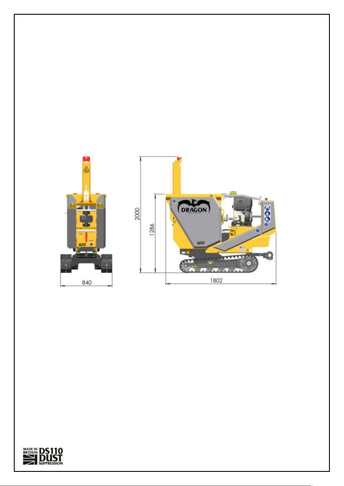
Specifications ..........................................................................................................................................5
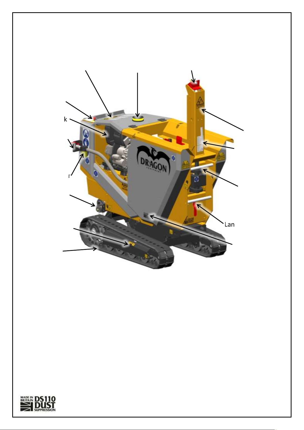
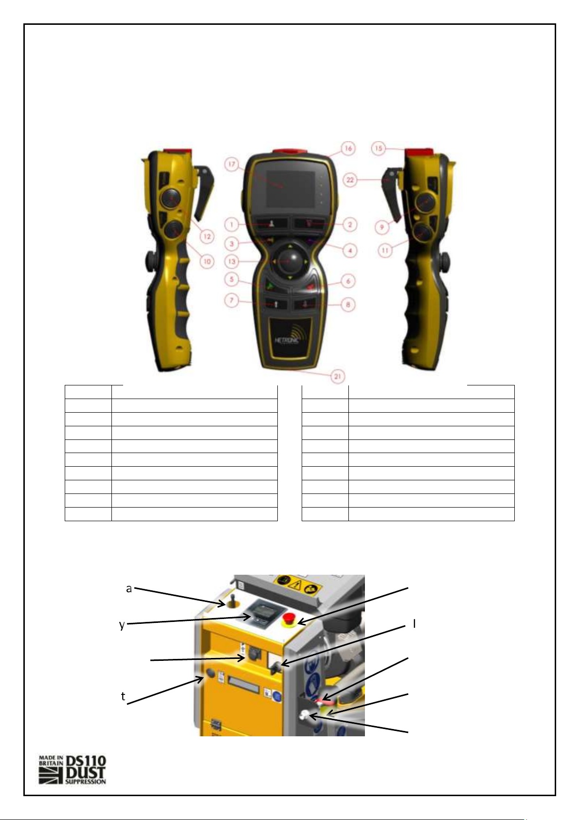
Parts Locator........................................................................................................................................6
Safe Working...........................................................................................................................................7
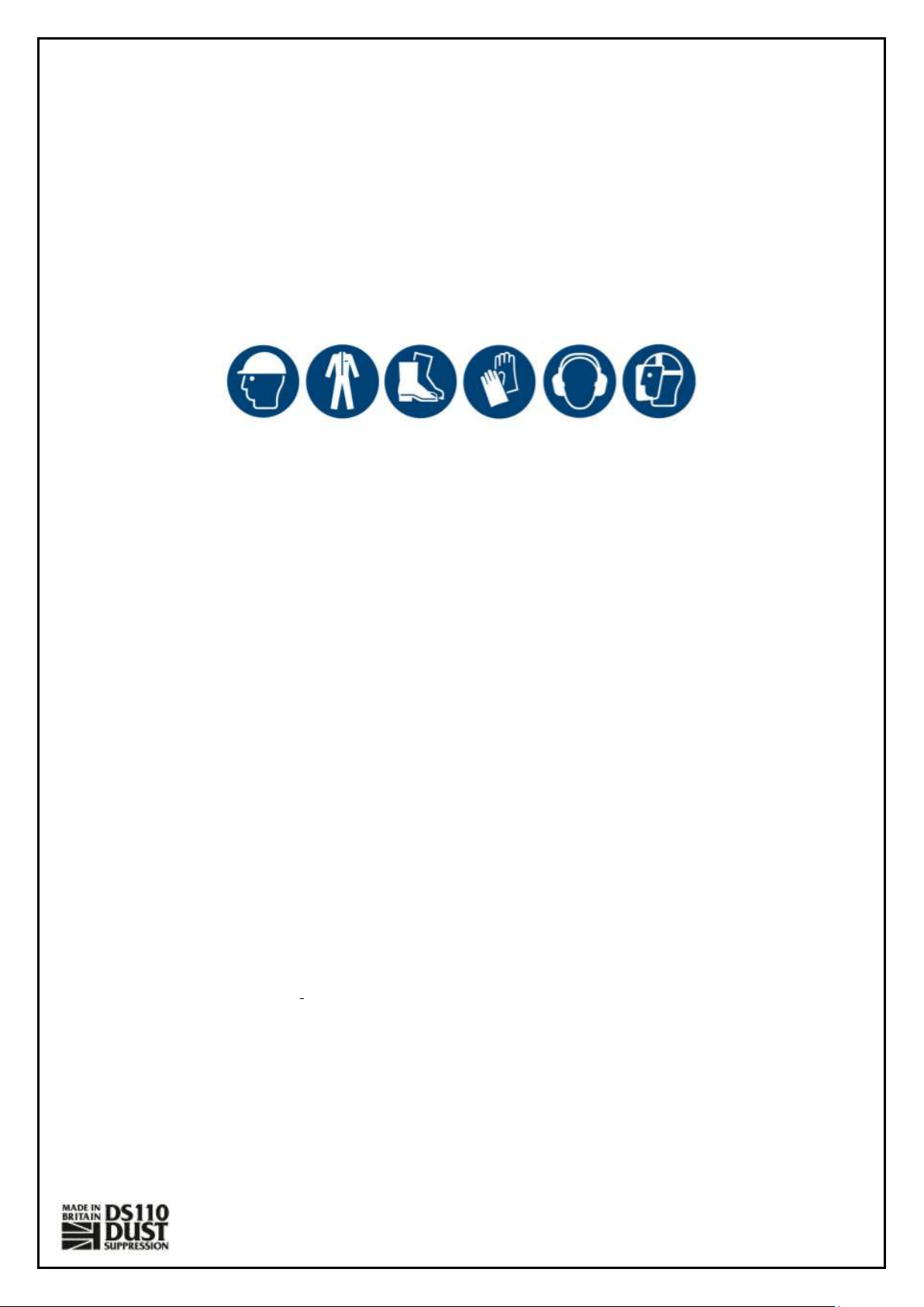
Operator’s Personal Protective Equipment (PPE).................................................................................7
Basic Operation Safety.........................................................................................................................7
General Safety Matters........................................................................................................................7
Engine Noise........................................................................................................................................8
Refuelling.............................................................................................................................................8
Operating Instructions............................................................................................................................9
Storage and Parking...........................................................................................................................10
Starting the Machine .........................................................................................................................10
Checks Before Starting..................................................................................................................10
Starting Procedure........................................................................................................................10
......................................................................................................................................................11
Stopping the Engine...........................................................................................................................11
Emergency Stopping ..........................................................................................................................11
Operating the Machine......................................................................................................................12
Checks Before Tracking.................................................................................................................12
Tracking the Machine....................................................................................................................12
Spraying Water ..................................................................................................................................12
Checks Before Spraying Water......................................................................................................12
Manual Water Mode.....................................................................................................................12
Using the Teach/Auto Function ....................................................................................................12
Using the High-Pressure Lance .....................................................................................................13
Lowering the Mast ........................................................................................................................13
Service Instructions...............................................................................................................................14
Service Schedule................................................................................................................................15
Engine Servicing ............................................................................................................................15
Hydraulic Hose Check....................................................................................................................15
Changing Hydraulic Oil Filter.........................................................................................................16
Changing Hydraulic Oil and Filter..................................................................................................16
Grease Moving Parts.....................................................................................................................17
Grease Bearings ............................................................................................................................17