3
Installing a Single Heat Enable Battery
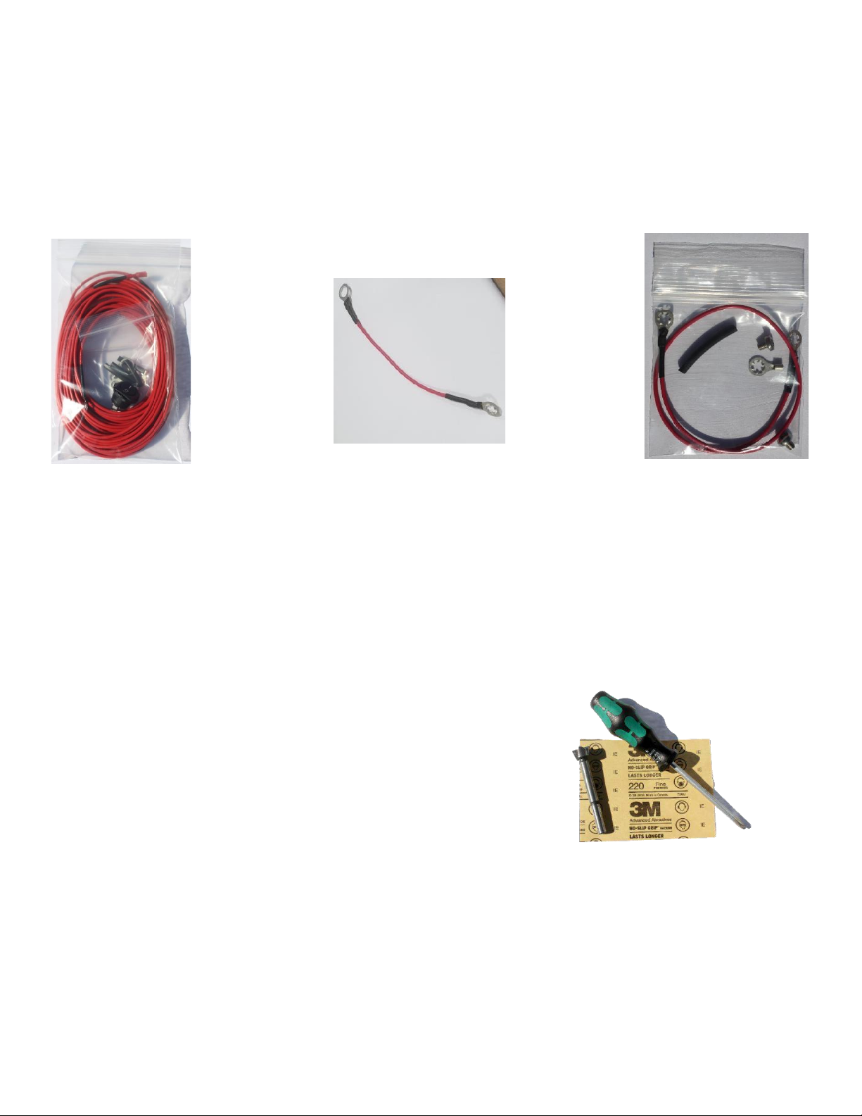
Included in every purchase of a heat battery is a standard heater enable
jumper wire. See Figure 2.
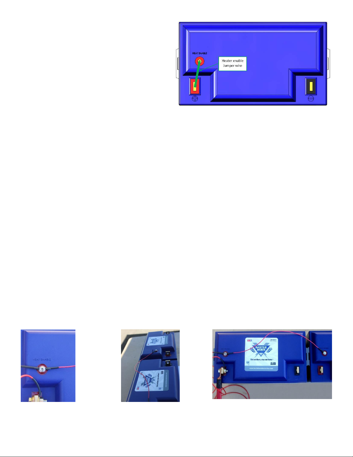
To enable the heating function, use the provided jumper to connect the
POSITIVE terminal and the heater enable stud.
Step One: Making a connection on the Positive Terminal
The 5/16”side of the heater enable jumper wire should go on the positive
terminal connection between the washer and the nylok. The connection
should then be torqued down using a ½” wrench, a ½” socket and a torque
wrench set to 10’ lbs. See Figure 12.
Please note, once the connection had been made, the heater enable jumper
wire, the connection is now live at 12V so avoid any contact with other live
wires or grounds. Also note that the heater enable post is not current carrying
itself so this connection should not spark when contact is made.
Step Two: Enabling the Heat Function
To enable the heat function on the battery, remove the screw and place the other end of your jumper wire onto the post. It is important that you do not over tighten
this connection. The connection should be tightened just enough to engage the lock washer feature on the ring terminal itself, so that vibration does not rattle the
connection loose. Now that the connection is tightened down, the internal heating function of the battery will be activated.
Step Three: Deactivating the Heat Enable Function
To deactivate the heat enable function on your BB10012H, simply remove the heat enable jumper wire from the heat enable post. Remember to tape down the end
of heat enable jumper wire with electrical tape and cover the ring terminal, so it does not make contact with other live wires or grounds. Be sure to put the heat
enable screw back into the post so you don’t lose it.
Installing Multiple BB10012H’s
If you purchased multiple Heat Enabled Batteries, there are two ways in which you can set up the heat enable function for your battery bank.
Option One: The Heat Enable Jumper Wire
The first option is to install an individual heat enable jumper wire on every single battery using the steps above from the “Installing a Single Heat Enable Battery”
section. Please note, if you proceed with this option, each battery must be manually disconnected and reconnected to activate or deactivate the heat enable
function. This option is recommended for batteries connected in parallel only.
Option Two: Daisy Chained
For option two you will use the Add-on Kit. We suggest that you configure your daisy chain set up first, then install the jumper from the heater post to the positive
terminal with the on/off switch in line. Whether your system is in series, parallel, or series-parallel you can daisy chain the enables together to control the heat
function from a single switch.
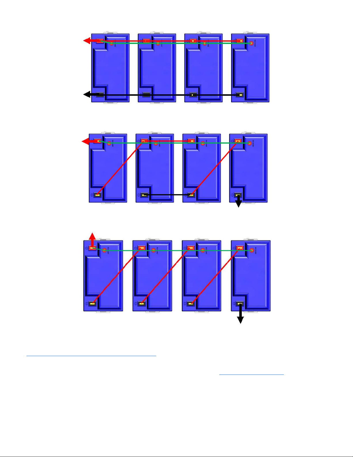
*ALWAYS ENABLE FROM THE HIGHEST VOLTAGE. For example, if you have a 48V system, make sure you jumper from the positive terminal that is at 48 volts to the
enable stud. See Wiring Diagrams Section on page 5.
Installing the Add-on Kit
To install the Add-on Kit, you will still need to install the heat enable jumper wire on one battery. For systems set up in series, the heat enable jumper wire should be
installed on the battery with the highest voltage. On the selected battery, you will remove the M4 x 4mm long screw that comes standard for the Heat Enable post.
Place the 14-inch jumper on the enable post with the main jumper and use the M4 x 5mm long screw from the Heat Enable Battery Kit bag and tighten them down
together. Take the free end of the jumper wire and install it onto the next battery. Repeat installation of the 14-inch jumper wire for all batteries in the bank. For each
heater enable post you have two jumper wires connected to, you will need to swap out the M4 x 4mm crew that comes standard out for the M5 x 5mm screw that
comes in the Add-on kit.
Figure 4: Heat Enable Jumper Wire Setup
Figure 5: Close up of Heat
Post with Add-on Kit
Figure 7: Top view of daisy chained heat enable post
Figure 6: Side view of daisy
chained heat enable post