Draminski ESTROUS DETECTOR User manual

ISO 9001:2008
RU
ES
FR
MANUAL
BEDIENUNGSANLEITUNG
MODE D’EMPLOI
INSTRUCCIONES DE USO
ИНСТРУКЦИЯ ОБСЛУЖИВАНИЯ
EN
ELECTRONIC ESTROUS
DETECTOR (ED)
Estrous detector for cows, mares, ewes and sows.
www.draminski.com
DE

1
EN
TABLE OF CONTENTS
INTRODUCTION . . . . . . . . . . . . . . . . . . . . . . . . . . . . . . . . . 3
DESIGN . . . . . . . . . . . . . . . . . . . . . . . . . . . . . . . . . . . . . . . 5
CHECKING THE DEVICE AND FIRST MEASUREMENTS . . . . . . . . . 7
MEASUREMENTS IN ANIMALS . . . . . . . . . . . . . . . . . . . . . . . .11
RESULT INTERPRETATION . . . . . . . . . . . . . . . . . . . . . . . . . . .15
DISINFECTION. . . . . . . . . . . . . . . . . . . . . . . . . . . . . . . . . . .19
FINAL NOTES FOR USERS. . . . . . . . . . . . . . . . . . . . . . . . . . . .23
BATTERY REPLACEMENT . . . . . . . . . . . . . . . . . . . . . . . . . . . .25
TECHNICAL DATA. . . . . . . . . . . . . . . . . . . . . . . . . . . . . . . . .27

There are three versions
of the device for each
of the animals:
For cows and mares (EDc).
For ewes (EDs).
For sows (EDp).

3
EN
INTRODUCTION
CHAPTER 1

4
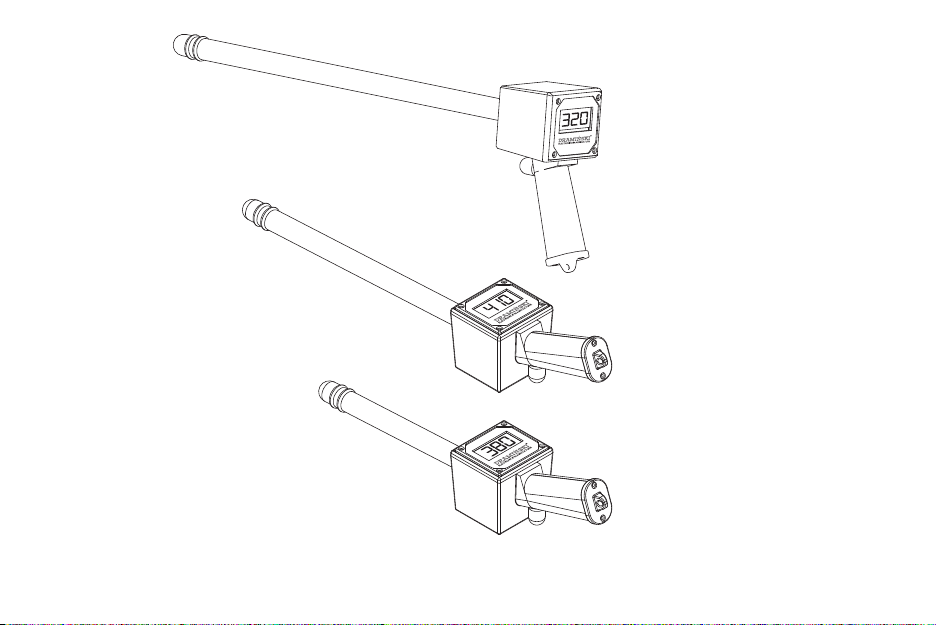
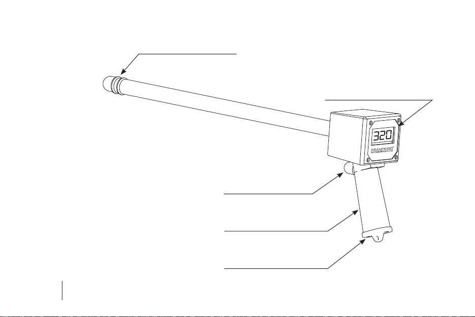
Electronic estrous detector:
• Makes it easier to determine an optimum mating
time for females with atypical estrous cycles.
• It enables the user to detect an asymptomatic
estrous period (the so called silent heat).
• Makes insemination more eective.
• Improves the economic performance of farms.
Oneof themost importantelementsofreproduction
management in livestock, is the detection of estrous
period, which is due to the close dependence of
female insemination eectiveness on the accurate
time of performing the insemination.
Research shows that there is a high rate of
undetected estrous periods in breeding practice.
Estrous usually proceeds very dynamically, which
can make it dicult for all animal breeders to
detect it regularly. Estrous and ovulation periods
are short, so it's easy to overlook them in the case of
infrequent or careless observations.
Therefore, various biotechnical methods of estrous
observation have been investigated, one of them
being the measurement of electrical resistance of
the vaginal mucus during estrous.
Knowledge of physiology and in particular
changes occurring in female reproductive
organs, demonstrated that changes in the ovaries
are accompanied by changes in the electrical
resistance of the animal's vaginal mucus. It is worth
emphasising that close relationships were also
noted between changes in electrical resistance of
the vaginal mucus and the level of hormones.
All the above phenomena and relationships related
to changes in vaginal mucus resistance were
used by DRAMIŃSKI to design an ELECTRONIC
ESTROUS DETECTOR.

5
EN
CHAPTER 2
DESIGN

6
A probe with two measuring
electrodes at the top.
3.5 digit LCD display.
A switch-on button protected
by a rubber cap.
A handle with a 9V battery
compartment.
A ap to close the
battery compartment.
At the end of the probe there are two
electrodes which measure the resistance
of the vaginal mucus. Electrical current
owing between the electrodes and
electric eld are absolutely harmless for
both animals and people.

7
EN
CHECKING THE DEVICE
AND FIRST MEASUREMENTS
CHAPTER 3

8
Upon switching on the device two ashing lines
will appear: --
After pressing the switch for three times: digits 1, 2, 3
will be displayed, which indicate three consecutive
measurements have been recorded.
12
3
After pressing the switch again, the device
will display a result, which will be the eect of
a measurement cycle 1 0, showing that the battery
level is sucient, the device works properly and the
probe is not immersed in any solution.
(ie: the measurement are made in the air)
1 0
The lowest unit shown is 10, while the full range is
between 0 and 1990 units. When the highest value
is exceeded, the numbers 1 0, will be displayed,
similar to when the measurement is taken in
the air. The measurement range of the device is
several times bigger than the maximum value of
vaginal mucus resistance. If the measurement is
taken correctly, it is not possible to exceed the
measurement range.

9
EN
You can also check the device is working
correctly by testing it in saline as follows:
1. Immerse the probe vertically in a glass containing
clean water at room temperature. Resting the
probe in the middle of the bottom of the glass,
perform a measurement cycle and read the
result. It will probably be 1 0 which means that
the measuring range has been exceeded, as the
resistance of clean water is very high.
2. Next, add a small pinch of salt, mix it well with the
water, immerse the probe as previously stated
and perform the measurement cycle again. After
adding the salt, the result will change, which
is dependent on the solution concentration,
as salt decreases resistance (lower resistance =
lower results).

10

11
EN
MEASUREMENTS IN ANIMALS
CHAPTER 4

12
1. Before beginning the measurement always make
sure that the electrodes are clean and degreased.
2. While using the ELECTRONIC ESTROUS DETECTOR
you should not use any lubricants, as they will
reduce the electrodes' contact with mucus, which
will distort the results.
3. Check the detector's operation to make sure that
the battery has adequate power.
4. Prepare a disinfectant in accordance with the
disinfectant manufacturer's instructions in
order to sterilize the probe (more details in the
chapter DISINFECTION).
5. If the vulval area is dirty, clean it or wipe o with
a disposable towel.
6. All rst time users of the ELECTRONIC ESTROUS
DETECTOR are advised to take several or
a dozen measurements in female animals that are
undoubtedly in their estrous period, in order to
master the measuring technique.

13
EN
Taking a measurement
If necessary, ask another person to assist you in
taking a measurement.
Part the animal's vulva
and delicately begin
inserting the disinfected
probe into the vagina.
At the beginning it is
best to insert the probe
from bottom to top, at
a 45 degree angle, to
avoid inserting the probe
into the urinary tract.
Next, insert it further until
resistance is felt, so that
the end of the probe with
both electrodes is placed
at the end of the animal's
vagina, i.e. at the cervical
canal. Then make 2 or 3
half turns to achieve the
best possible contact of electrodes with the mucus.
Measurement should be taken at the lower edge of
the cervical canal, always in the same manner.

14
NOTE! The depth of probe insertion depends on
the length of the vagina and may vary in dierent
animals, so you should always follow the principle
of inserting the probe until resistance is felt.
1. Push the power button. Two ashing lines will
be displayed. --
2. Perform a measurement cycle, remembering
to make 2-3 half turns between each of the
measurements, each time after you push the
power button.
An example of a measurement cycle:
1
23
320
4. Take out the probe from the animal's vagina and
remember or note down the result.
5. Turn o the device by holding the power button
for over 3 seconds or wait until it turns itself o
automatically after 30 seconds.
6. Wash and disinfect the device in the manner
shown in the chapter DISINFECTION.

15
EN
CHAPTER 5
RESULT INTERPRETATION

16
ESTROUS ESTROUS Time
Figure 1
mucus resistance
Figure 1 shows a diagram outlining the pattern of
changes in the vaginal mucus resistance during
the ovarian cycle with the moment of estrous.
If an animal is in the estrous period, a high level
of resistance is detected (depending on female
species, e.g. about 300 units or more in cows).
As the peak time of estrous is approaching, the
resistance decreases, reaching the minimum value
(e.g. about 200 units in cows) and then it increases
again to a high level and remains at this level until
the next estrous.
In practice, when taking measurements, you should
capture the minimum value and then the moment
of rapid increase of results. Therefore, during the
estrous period measurements should be taken with
appropriate frequency. Taking measurements too
rarely (e.g. once in a few days) will lead to a wrong
interpretation of results and miss the important
moment of ovulation.

17
EN
ESTROUS FALL
PREGNANCY
Time
Figure 2
mucus resistance
Figure 2 shows a diagram outlining resistance in
the case of eective mating or insemination. The
resistance value after the end of estrous period and
during pregnancy stays on a high level until the
date of birth.
Estrous detection:
Examples of changes in mucus resistance in dierent
species are illustrated by the diagrams below. You
should bear in mind that estrous detection consists
of capturing the minimum value and then the
moment of marked increase in value.
Such an increase marks the impending ovulation
which should take place within several hours and
up to over a dozen hours. It is the best time for
insemination or mating.
When examining animals you should observe the
changes in resistance levels. The estrous period
does not last long, so at this time measurements
should be taken more often than once a day.

18
ESTROUS Day of the cycle
Ovulation
-4 -3 -2
400
320
-1 0+1 +2 +3
-4 -3 -2
400
200
-1 0+1 +2 +3
ESTROUS Day of the cycle
Ovulation
-4 -3 -2
450
350
250
-1 0+1 +2 +3
ESTROUS Day of the cycle
Ovulation
-4 -3 -2
600
400
-1 0+1 +2 +3
ESTROUS Day of the cycle
Ovulation
Remember! Mucus resistance values during and outside the estrous period as shown on the gures
are only examples. It should be emphasized that in practice the values vary depending on an
individual animal.

19
EN
CHAPTER 6
DISINFECTION
Table of contents
Languages:
Popular Farm Equipment manuals by other brands

SCHMOTZER
SCHMOTZER Venterra 2K KPP-LSC Translation of the original operating instructions

Tube-Line
Tube-Line TL1100R Operator's manual

Toro
Toro Reelmaster 33452 Operator's manual

MacDon
MacDon R113 Operator's manual

KUHN
KUHN FC 202 R Assembly & operators manual

CAMPAGNOLA
CAMPAGNOLA SPEEDY Use and maintenance manual