Drawell MDF-40V50 User manual

User Manual
Please read operating manual before installation and operation.
Drawell International Technology Limited
Shanghai Drawell Scientific Instrument Co.,Ltd
Add : Suite 1506,Lane581 XiuChuan Rd.,PuDong New Area,Shanghai,China
Tel: 0086 21 50966080
Fax: 0086 21 50966080
Web : www.drawell.com.cn

0
OPERATION MANUAL
MEDICAL FREEZER
MDF-40V50
VERSION: 2017-4
(MDF-40V50)

1
Statement:
Thank you for buying our medical refrigerator. For your safe and convenient use and reasonable maintenance
of the product, please read the operation instruction carefully and keep it properly for reference.
For damages of any instrument due to the fact that the user does not use the product according to the
instrument operating environment declared in the handbook or injuries due to the fact that individual does not
operate the product according to safety instructions, we have no obligations and responsibilities to be in
charge of them.
The user must accomplish the following three points when using the product:
1. Always use protective devices correctly (including clothes, gloves, goggles, etc.);
2. Always adopt good health habits and operate strictly according to the product instruction;
3. Everyone is obliged to be in charge of one’ own safety.
4.Not Allowed direct contact with patients, use or affect the product and in the product storage items.
5.Products without sterilization.
6.The product is used only for storage, not during use with other materials, Organization and Technology in
combination.
7.Products can not be used to measure or analysis.
8.Life and storage life of the products is irrelevant.
9.Some models need to regularly add supplies, such as printer paper, test tubes, etc.
10.This product is non-explosion-proof products.
11.Non flash freeze equipment, is limited to keeping the temperature used.
Due to our fast product update, there may be differences between function of the product you bought and the
function mentioned in the instruction, please in kind prevail.

2
CONTENTS
I. Main performance and characteristics of the product................................................ 3
II. Precautions....................................................................................................................... 3
III. Range of application.......................................................................................................5
IV. Preparation for use.........................................................................................................5
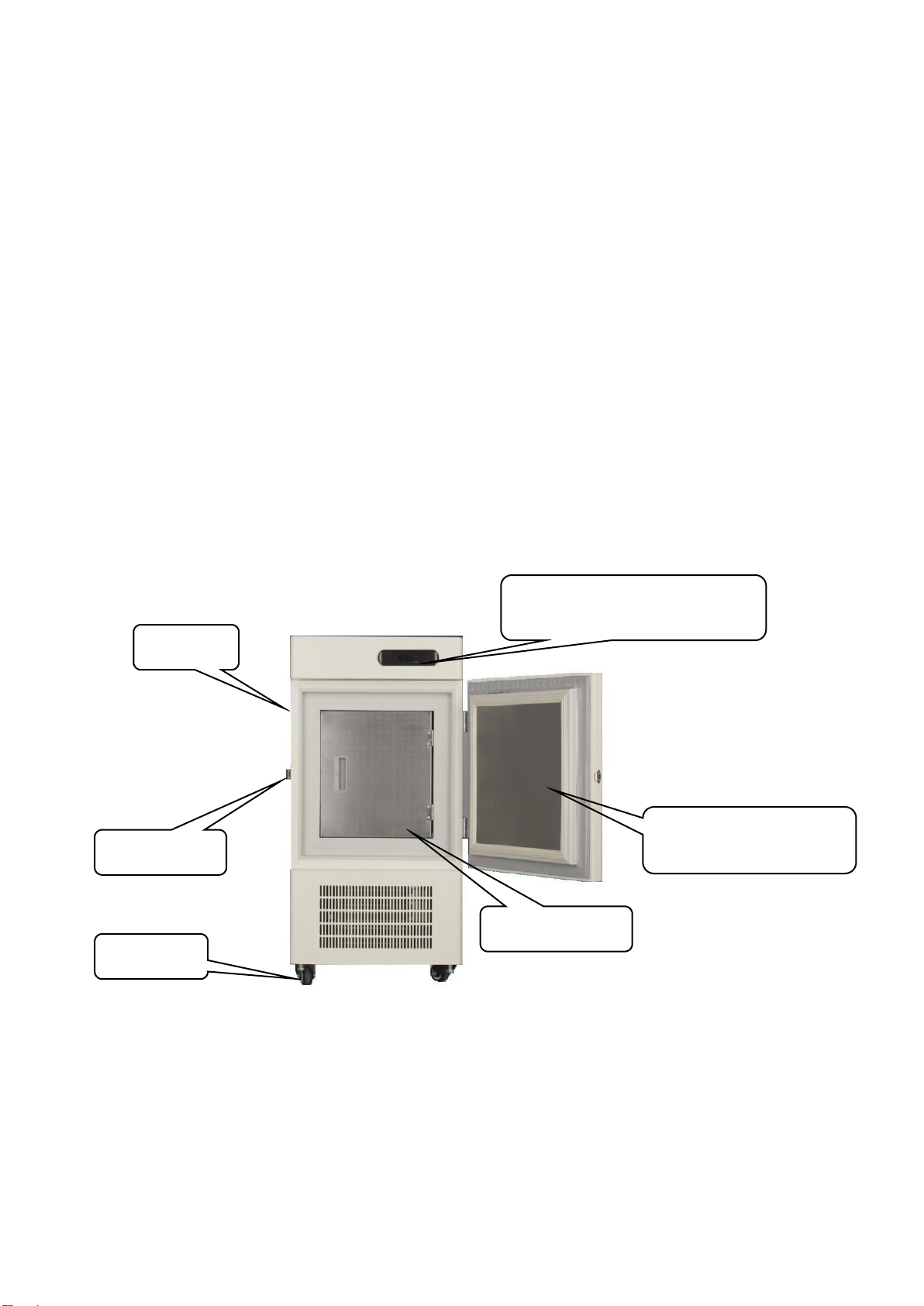
V. Structure diagram............................................................................................................5
VI. Start and test machine.................................................................................................. 6
VII. Model and main technical parameters...................................................................... 6
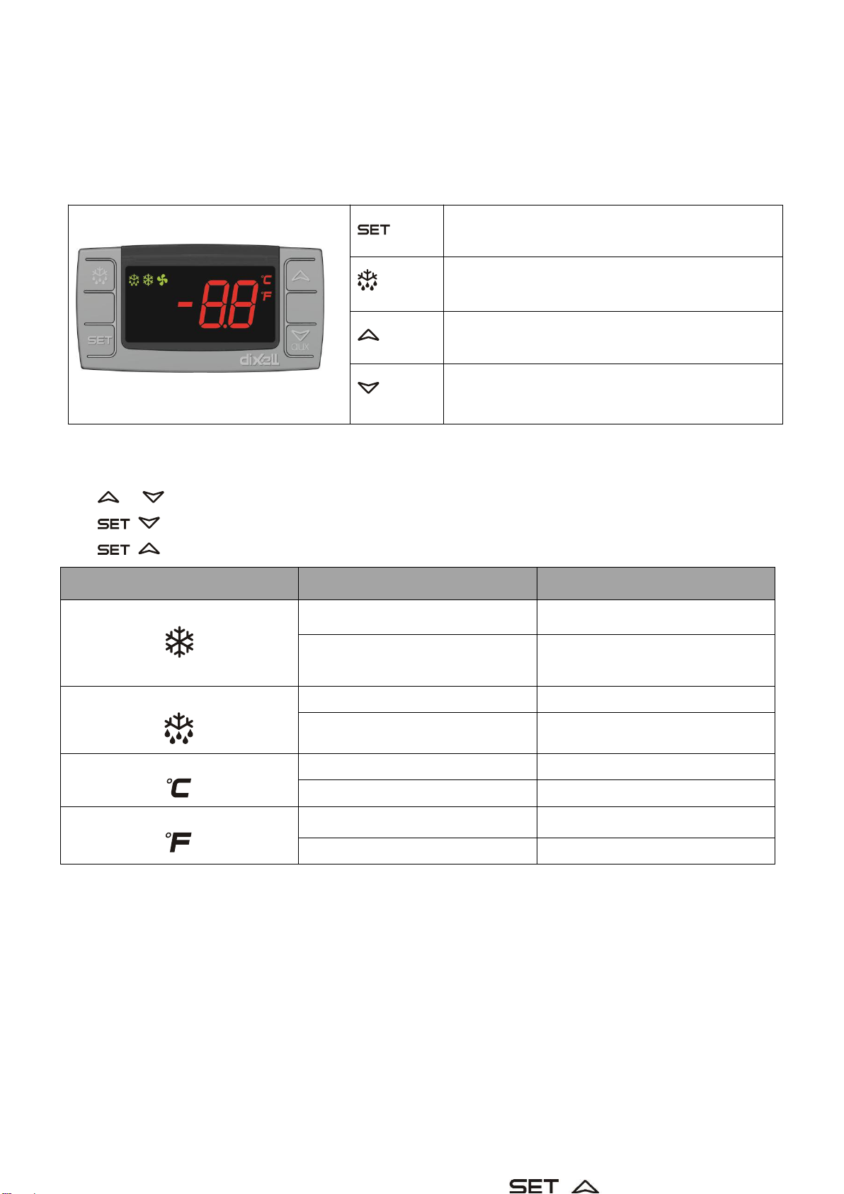
VIII. Functions and basic operation of controller............................................................ 7
8.1 Control panel structure........................................................................................... 7
8.1.1 Keys Combination..........................................................................................7
8.1.2 How to see the set point............................................................................... 7
8.1.3 How to change the set point.........................................................................7
8.1.4 How to start a manual defrost (only xr02cx)............................................. 8
8.1.5 How to change parameter value................................................................. 8
8.2 parameters................................................................................................................8
8.3 Digital inputs...........................................................................................................10
8.4 Alarm signaling...................................................................................................... 10
8.4.1 alarm recovery..............................................................................................11
8.5 connection diagram...............................................................................................11
8.5.1XR01-02CX –1 X 8A –12VAC/DC....................................................11
8.5.2 XR01-02CX –20A OR 8A -- 110VAC OR 230VAC...........................11
IX. Schematic circuit diagram.......................................................................................... 12
X. Storage essentials.........................................................................................................12
XI. Maintenance..................................................................................................................13
XII. Non-fault phenomenon.............................................................................................. 13
XIII. General fault analysis and removal........................................................................ 14
XIV. Packing List................................................................................................................ 14

3
I. Main performance and characteristics of the
product
Thermal insulating door and secondary seal door are adopted for use convenience. The loss of
refrigeration capacity is reduced and the energy consumption is saved.
Air-cooled condenser is adopted which is provided with good heat dissipation and fast refrigerating speed.
Stainless steel inner and tube-in-sheet evaporator are adopted. Things can be put in or taken out easily.
The refrigeration effect is good and the freezer can be cleaned easily.
Import microcomputer temperature controller is adopted for accurate temperature control. The
temperature inside the freezer is displayed digitally. With elegant appearance, the freezer can be used
conveniently. Users can regulate and check the inside temperature and the working state without opening
the door.
The microcomputer control is more accurate and safer.
The system is equipped with a safety protection device for ensuring the safe and reliable operation of the
system.
The refrigerating system all adopts imported parts which provide good reliability and long service life to the
system.
II. Precautions
The sign of “ ” means the place is dangerous to human bodies, or the use pattern is harmful to
products, or alarm users should pay special attention to this.
:It is strictly prohibited to unpack the outer packing case for transportation.
The ultra low temperature freezer should be used under the environmental temperature of 10℃~32℃. It is
suggested to use it under the environment with air conditioning.
:The slant angle of the body of the ultra low temperature freezer should not be larger than 45°in
transportation to avoid faults of the compressor or the system.
:After unpacked, the freezer should be placed on flat and firm ground near to the power socket.
:Do not put it near the heat source and avoid the sunshine.
:The ultra low temperature freezer should be stored in a dry and drafty room without corrosive gas
surrounding.
:If the ultra low temperature freezer has to be stopped for a long period, it should be cleaned inside and
outside and then covered properly with a plastic housing.
:The power supply is 220V/50Hz. If the voltage is instable, please equip a power regulator which is
above 3000VA and please use it alone.
:It is necessary to provide individual one-phase three-hole socket and proper fuse for the ultra low
temperature freezer.
:The ultra low temperature freezer must be provided with reliable independent ground wire. The ground

4
wire cannot be connected with gas pipe, stem heating pipe and water pipe and the zero line of
single-phase source should not be taken over as well.
:If the power connect wire has to be lengthened, the sectional area of the conductor is larger than or
equals to 1.5mm. The conductor can be single-stranded or multi-stranded. It is strictly prohibited to use
multipurpose socket for connection.
:The ultra low temperature freezer cannot lean against the wall. The space of at least 30cm should be
left at the machine room for normal running of the system.
:No water is allowed to be splashed on the outside body of the ultra low temperature freezer. When
scouring the ground, it is strictly prohibited to splash water into the control panel and the compressor room.
It is also prohibited to use the product in the rain or under the environment with the relative humidity of
larger than 85%. Otherwise, faults such as electric leakage etc. may be caused.
:With continuous operation system, the ultra low temperature freezer should be restarted after five
minutes in case of power failure or machine halt to prevent the compressor or the system from being
damaged.
:The key of the ultra low temperature freezer should be kept out of the reach of children to avoid
accidents.
:Inflammable, explosive and volatile dangerous articles and acid and alkali etc. with strong
corrosiveness are never allowed to be put in the ultra low temperature freezer.
:The ultra low temperature freezer cannot be used under inflammable and explosive gas environment.
Be sure not to spray combustibles such as paint, coating etc. to avoid fires.
:The door should be closed tight. Otherwise, the normal operation and usage of the system may be
affected.
:The service environment pollution grade of the ultra low temperature freezer is grade 2.

5
III. Range of application
The ultra low temperature freezer is provided to departments of medicine, health, medical treatment, food,
chemical industry, scientific research etc. for low-temperature freezing, storage, test and subzero treatment.
IV. Preparation for use
After unpacking, remove all outer packing material.
Checking standard accessories and data: check and compare the inside accessories and data with the
packing list【please see related pages of the directions】.
Please place the ultra low temperature freezer at proper location 【please refer to relevant terms in
Precautions】.
It would be best to clean the freezer before use【please refer to relevant terms in Maintenance】.
V.Structure diagram
(MDF-40V50 diagram)
Door Lock
Cabinet
Temperature Controller and
Power Switch
Trundle
Inside Door
Thermal Insulation Outer
Door

6
VI. Start and test machine
After installation, keep the device standing for 12 hours at least to return the compressor oil.
After installation and first use testing, please adjust the castors to fix the device.
Plug in the socket and switch on the power switch (located at the right side of the temperature controller
on the front part of the body). Then the power supply indicator light is on. In order to ensure the normal
running of the cryogenic freezer, be sure to use the three-hole socket which is above 16A.
The system will automatically start the compressor, and the refrigeration indicator light is on. The system
goes into refrigerating cycle state.
After the power has been supplied for a period of time, the temperature inside the freezer decreases
obviously, which indicates the refrigerating system is working normally.
Before storing articles, please keep the freezer running in empty state. When the freezer is running
stably (it is best to keep it running in empty state for 7hours above) and the inside is cooled completely,
the cold store articles can be put in.
VII. Model and main technical parameters
Model
MDF-40V50
Type
Vertical type
Total effective volume (L)
50
Storage temperature
-10℃~-40℃
Rated voltage (V)
~220
Frequency (Hz)
50
Rated power(W)
250
Power consumption (kW.h/24h)
3.5
Electric-shock protection class
Class ⅠType B
Type of alarm
Sound-light alarm
Climate type
SN/N
Refrigerating fluid
Fluoride-free mix
Net weight of machine (kg)/ Gross weight(kg)
75/95
Machine dimensions W×D×H(mm)
540×620×1115
Notes: technical parameters in this table are measured at the standard state. Please be subject to
the nameplate of the goods freezer without prior notice in case of variation.

7
VIII. Functions and basic operation of controller
8.1 Control panel structure
computer control system is adopted by the ultra low temperature freezer
To display target set point, in programming mode
it selects a parameter or confirm an operation
To start a manual defrost (Only XR02CX)
In programming mode it browses the parameter
codes or increases the displayed value
AUX
In programming mode it browses the parameter
codes or decreases the displayed value
8.1.1 Keys Combination
+ To lock or unlock the keyboard
+ To enter in programming mode
+ To return to room temperature display
LED
State
Signification
On
Compressor enabled
Flashing
Anti short cycle delay enabled
(AC parameter)
On
Defrost in progress
Flashing
Dripping in progress
On
Measurement unit
Flashing
Programming mode
On
Measurement unit
Flashing
Programming mode
8.1.2 How to see the set point
1.Push and immediately release the SET key, the set point will be showed;
2.Push and immediately release the SET key or wait about 5s to return to normal visualisation.
8.1.3 How to change the set point
1.Push the SET key for more than 2 seconds to change the Set point value;
2.The value of the set point will be displayed and the “°C”or “°F”LED starts blinking;
3.To change the Set value push the o or n arrows within 10s.

8
4.To memorise the new set point value push the SET key again or wait 10s.
8.1.4 How to start a manual defrost (only xr02cx)
Push the DEF key for more than 2 seconds and a manual defrost will start
8.1.5 How to change parameter value
To change the parameter’s value operate as follows:
1.Enter the Programming mode by pressing the SET+ keys for 3s (“°C”or “°F”LED starts
blinking).
2.Select the required parameter. Press the “SET”key to display its value
3.Use or to change its value.
4.Press“SET”to store the new value and move to the following parameter.
To exit: Press SET+ or wait 15s without pressing a key.
NOTE: the set value is stored even when the procedure is exited by waiting the time-out to expire.
8.2 parameters
Hy Differential: (0,1°C÷25°C / 1°F÷45°F) Intervention differential for set point. Compressor Cut
IN is SET POINT + differential (Hy). Compressor Cut OUT is when the temperature reaches the
set point.
LS Minimum SET POINT: (-55°C÷SET/-67°F÷SET): Sets the minimum value for the set point..
US Maximum SET POINT: (SET÷99°C/ SET÷99°F). Set the maximum value for set point.
ot First probe calibration: (-9.9÷9.9°C /-17÷17°F) allows to adjust possible offset of the first
probe.
od Outputs activation delay at start up: (0÷99min) This function is enabled at the initial start up of
the instrument and inhibits any output activation for the period of time set in the parameter.
AC Anti-short cycle delay: (0÷50 min) minimum interval between the compressor stop and the
following restart.
Cy Compressor ON time with faulty probe: (0÷99 min) time during which the compressor is active
in case of faulty thermostat probe. With Cy=0 compressor is always OFF.
Cn Compressor OFF time with faulty probe: (0÷99 min) time during which the compressor is OFF
in case of faulty thermostat probe. With Cn=0 compressor is always active.
CH Kind of Action: cL= cooling action; Ht = heating action.
Display
CF Measurement unit: (°C÷°F) °C =Celsius; °F =Fahrenheit. WARNING: When the measurement
unit is changed the SET point and the values
have to be checked and modified if necessary).
rE Resolution (only for °C):(dE ÷in) dE= decimal between -9.9 and 9.9°C; in= integer
dy Display delay: (0÷15 min.) when the temperature increases, the display is updated of 1 °C/1°F
after this time.

9
Defrost(only xr02cx)
id Interval between defrost cycles: (0÷99 ore) Determines the time interval between the
beginning of two defrost cycles.
Md Maximum length for defrost: (0÷99 min. with 0 no defrost) when P2=n, (not evaporator probe:
timed defrost) it sets the defrost duration, when P2 = y (defrost end based on temperature) it sets
the maximum length for defrost.
dF Display during defrost: (rt / it / St / dF) rt= real temperature; it= start defrost temperature; St=
SET-POINT; dF= label dF.
Alarm
AU Maximum temperature alarm: (AL÷99°C/99°F) when this temperature is reached the alarm is
enabled, after the “Ad”delay time.
AL Minimum temperature alarm: (-55÷AU°C /-67÷AU°F) when this temperature is reached the
alarm is enabled, after the “Ad”delay time.
Ad Temperature alarm delay: (0÷99 min) time interval between the detection of an alarm condition
and alarm signalling.
dA Exclusion of temperature alarm at startup: (0÷99 min) time interval between the detection of
the temperature alarm condition after instrument power on and alarm signalling.
Digital
iP Digital input polarity: (oP ÷cL) oP= activated by closing the contact; cL= activated by opening
the contact;
iF Digital input configuration: (EA/bA/do/dF/Au/Hc) EA= external alarm: “EA”message is
displayed; bA= serious alarm “CA”message is displayed; do= door switch function; dF= defrost
activation; Au =not used; Hc= inversion of the kind of action;
di Digital input delay: (0÷99 min) with iF=EA or bA delay between the detection of the external
alarm condition and its signalling. . With iF=do it represents the delay to activate the door open
alarm.
dC Compressor and fan status when open door: (no/Fn/cP/Fc): no= normal; Fn = Fans OFF; cP
=Compressor OFF; Fc = Compressor and fans OFF;
rd Regulation with door open: (n÷y) n = no regulation if door is opened; Y= when di is elapsed
regulation restarts even if door open alarm is present;
Other
Pt Parameter code table
rL Software release

10
8.3 Digital inputs
The free voltage digital input is programmable in different configurations by the “iF”parameter.
Door switch
It signals the door status and the corresponding relay output status through the “dC”parameter: no
=normal (any change); Fn = Fan OFF; CP = Compressor OFF; FC = Compressor and fan OFF.
Since the door is opened, after the delay time set through parameter “di”, the door alarm is enabled,the
display shows the message “dA”and the regulation restarts if rd = y. The alarm stops as soon as the
external digital input is disabled again. With the door open, the high and low temperature alarms are
disabled.
External alarm(iF=EA)
As soon as the digital input is activated the unit will wait for “di”time delay before signalling the “EA”
alarm message. The outputs status don’t change. The alarm stops just after the digital input is de-activated.
Serious alarm (iF=bA)
When the digital input is activated, the unit will wait for “di”delay before signalling the “CA”alarm
message. The relay outputs are switched OFF. The alarm will stop as soon as the digital input is de-
activated.
Start defrost(iF=dF)
It starts a defrost if there are the right conditions. After the defrost is finished, the normal regulation will restart
only if the digital input is disabled otherwise the instrument will wait until the “dd”safety time is expired.
Inversion of the kind of action: heating-cooling (iF=Hc)
This function allows to invert the regulation of the controller: from cooling to heating and viceversa.
8.4 Alarm signaling
Mess.
Cause
Outputs
"P1"
Room probe failure
Compressor output according to “Cy” e “Cn”
"P2"
Evaporator probe failure
Defrost end is timed
"HA"
Maximum temperature alarm
Outputs unchanged
"LA"
Minimum temperature alarm
Outputs unchanged
“EA”
External alarm
Outputs unchanged
“CA”
Serious external alarm
All outputs OFF.
“dA”
Door Open
Compressor and fans restarts

11
8.4.1 alarm recovery
Probe alarms P1”and “P2”start some seconds after the fault in the related probe; they automatically
stop some seconds after the probe restarts normal operation. Check connections before replacing the
probe. Temperature alarms “HA”and “LA”automatically stop as soon as the temperature returns
to normal values.
Alarms “EA”and “CA”(with iF=bL) recover as soon as the digital input is disabled.
8.5 connection diagram
8.5.1XR01-02CX –1 X 8A –12VAC/DC
8.5.2 XR01-02CX –20A OR 8A -- 110VAC OR 230VAC
NOTE: The compressor relay is 20(8)A or 8(3)A depending on the model.
NOTE: 120Vac connect to 6-7

12
IX. Schematic circuit diagram
X. Storage essentials
Before storing articles, please keep the freezer running in empty state. When the freezer is running
stably (it is best to keep it running in empty state for 5 hours above) and the inside is cooled completely,
the cold store articles can be put in.
Articles or other products put in the freezer in one time shouldn’t be too much. Proper clearance should
be left to help the circulation of the inside cold air.
The refrigerating system of the ultra low temperature freezer is a device used for maintaining low
temperature rather than a quick freezing device. If you want to store high capacity (high water-bearing
material), pre cooling them in other quick-freezing plant and then store them in the freezer to avoid
long-time running without stop of the refrigerating system.
When the initial storage capacity is large, a method of gradually lowering the temperature set should be
adopted. The temperature is lowered by 10℃in every step and then maintained for 1-2 hours until the
storage temperature is reached.
When storing plastic bag products, please note that do not get them close to metal edges to avoid
scratch of plastic bag.

13
XI. Maintenance
Body cleaning: please use non-corrosive neutral cleaning agent to clean the inside and outside
surfaces of the ultra low temperature freezer and then use dry cloth to wipe it up.
Notes: it is strictly prohibited to use water to directly wash the inside and outside surfaces of the freezer
so as not to affect the insulating property of electrical equipment. Boiling water, cleaner, acid, alkali,
gasoline, alcohol, benzene, corrosive cleaning agent and scrub-bush are forbidden in cleaning.
Clean dusts on the condenser frequently by banister brush or vacuum cleaner to maintain good
condensing effect.
Regularly wipe a little talcum powder on the door seal to extend the service life of the sealing strip.
If the ultra low temperature freezer has been running for a long time, frost may be easily accumulated on
the door seal, the opening part of the freezer and the side wall inside the freezer. If the frost layer is too
thick, the sealing property and the refrigerating property may be affected. Therefore, please defrost
regularly and wipe it clean with dry cloth.
The water shall not be dumped on the casing of the medical low temperature storage case or kept
indoors,Otherwise, it may damage the electrical insulation and lead to a fault.
Please use non-corrosive neutral cleaning agent to clean the inside and outside surfaces of the freezer
and then use dry cloth to wipe it up.
Do not allow children to use medical freezer to playing games
Not to put heavy objects on the refrigerator door or medical cap, to avoid the door or the top compression
deformation.
Machine halt: when stop using the freezer, unplug the power plug, clean it according to the above
method, cover it with a plastic bag after natural drying and put it on a ventilated and clean place.
XII. Non-fault phenomenon
Sound of running water can be heard in the ultra low temperature freezer: this is the sound of
refrigerating fluid running in the pipeline.
Compressor is hot: when the compressor is running, the surface temperature can reach to 70℃~90℃.
You may feel a little hot on the two sides of the body (close to the door body) when the freezer is running.
That is because the leak proof tube equipped in the freezer.
There is condensation on the door seal: in rainy and moist season or under the environment with higher
relative humidity, there may be condensation on the outer surface of the freezer and the door seal. Then
rub dry.

14
XIII. General fault analysis and removal
a.The ultra low temperature freezer does not work and there is no display on the controller
If the power plug wire is properly connected and the main power supply is plugged in
If the power switch is turned on
If the power socket is in good condition
If the fuse has been burned out
If the controller is broken or line is damaged: it is necessary to contact the nearby maintenance
department for overhaul
b.The compressor is running without stop, but the temperature inside the freezer does not decrease
The door is opened too often for too long: try to reduce the door-opening time
The storage capacity is too much: take some out or distribute evenly to keep the air inside the freezer
flow
The condenser is dirty and the heat dissipation is not good: clean the condenser (operate according to
relevant terms in Maintenance)
Refrigerant leeks or pipeline is blocked: it is necessary to contact the nearby maintenance department for
overhaul
The condensate fan in the machine room is broken: it is necessary to contact the nearby maintenance
department for overhaul
c.Large noise
If the outer packing has been all removed
If the freezer is placed smoothly
If the back part of the freezer body contacts with the wall: please operate according to relevant items in
Precautions.
The compressor is in abnormal operation only with drone: if the power voltage is within the defined limits,
and please operate according to relevant terms in Precautions.
The fan in the machine room makes a lot of noise: the fan is broken or contacts with something. It is
necessary to contact nearby maintenance department for overhaul
Notes: if the ultra low temperature freezer still cannot work normally after being inspected and handled
according to the above methods, please contact the maintenance department of our company in time.
XIV. Packing List
Model
User Manual
Key
Shelf
Buckle
MDF-40V50
1
2
1
4

Drawell International Technology Limited
Shanghai Drawell Scientific Instrument Co.,Ltd
Add : Suite 1506,Lane581 XiuChuan Rd.,PuDong New Area,Shanghai,China
Tel: 0086 21 50966080
Fax: 0086 21 50966080
Web : www.drawell.com.cn
Table of contents
Popular Medical Equipment manuals by other brands

Bertec
Bertec Balance Advantage HMD System user manual

Hillenbrand
Hillenbrand Hill-Rom P1440 user manual

Seers Medical
Seers Medical Medicare Bariatric SM3484 operating instructions

Otto Bock
Otto Bock 17LK3 Series Instructions for use

ConMed
ConMed Advantage instruction manual

VNS Therapy
VNS Therapy SENTIVA M3000 Programmer Technical guide

Darco
Darco Mecron X-patch Instructions for use

Edge Systems
Edge Systems HYDRAFACIAL Handpiece user guide

KLARITY
KLARITY SBRT System Instructions for use

medi
medi circaid juxtalite lower leg inelastic compression... Instructions for use

Medit
Medit Link user guide

Smiths Medical
Smiths Medical BCI SPECTRO2 10 Operation manual