DRE Waveline EZ User manual

DRE Waveline EZ
Service Manual

SERVICE MANUAL
Waveline EZ
Patient Monitor
Caution:Federal law (U.S.A.) restricts this device to sale by or on the order of a physician.
© 2010 DRE, Inc. All rights reserved. Ver 1.0,Issued date: Dec 28, 2010

DRE Inc.
Website: www.dremed.com
Address: 1800 Williamson Court
Louisville, KY 40223 USA
Toll Free (US call only): 502-244-4444
To obtain information about a warranty, if any, for this product, contact DRE Technical Services or your
local DRE representative.

- I -
TABLE OF CONTENTS
SECTION 1: INTRODUCTION....................................................................................................................... 4
1.1 MANUAL OVERVIEW ........................................................................................................................... 4
1.2 WARNINGS, CAUTIONS AND NOTES................................................................................................ 4
1.3 Waveline EZ PATIENT MONITOR DESCRIPTION............................................................................. 4
1.4 RELATED DOCUMENTS....................................................................................................................... 5
SECTION 2: INTRODUCTION AND SYSTEM DESCRIPTION.............................................................. 6
2.1 SYSTEM OVERVIEW ............................................................................................................................. 6
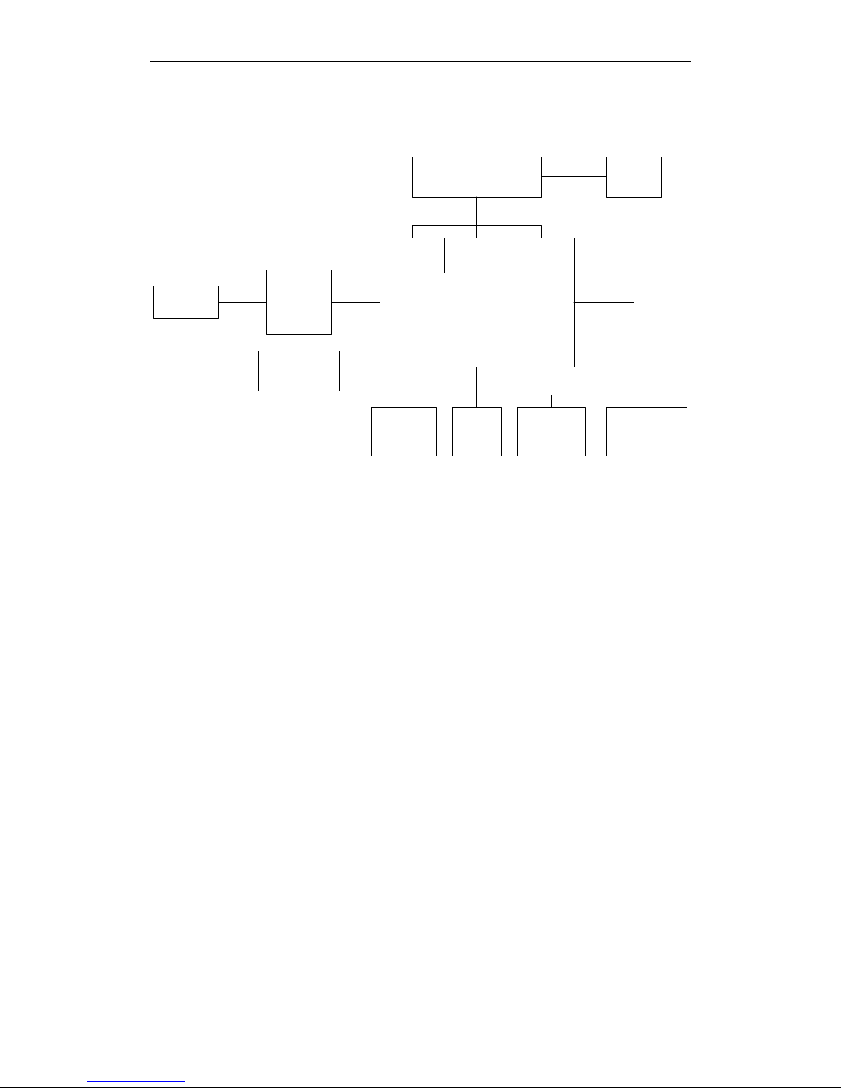
2.2 SYSTEM BLOCK DIAGRAM................................................................................................................. 6
2.2.1 POWER SYSTEM......................................................................................................................7
2.2.1.1
PIN ASSIGNMENT AND DESCRIPTION FOR AC-DC MODULE
.............................................8
2.2.1.2 PIN ASSIGNMENT AND DESCRIPTION FOR DC-DC MODULE
.............................................9
2.2.1.3 DC-DC MODULE TEST POINTS
...........................................................................................11
2.2.2
MAINBOARD (ARM-FPGA SYSTEM
,
ERT MODULE
(
ECG, RESP, TEMP,SPO2
)
)
...........11
2.2.2.1 PIN ASSIGNMENT AND DESCRIPTION FOR MAINBOARD
.................................................12
2.2.2.2 MAINBOARD TEST POINTS
.................................................................................................12
2.2.2.3 FPGA
.........................................................................................................................................13
2.2.2.4 ARM (ADVANCED RISC MACHINE)
........................................................................................13
2.2.2.5 ERT MODULE
(
ECG, RESP, TEMP, SPO2
)
........................................................................14
2.2.3 NIBP MODULE.........................................................................................................................15
2.2.3.1 PIN ASSIGNMENT AND DESCRIPTION FOR NIBP MODULE..................................18
2.2.4 SPO2 MODULE........................................................................................................................18
2.2.5 DISPLAY....................................................................................................................................19
2.2.5.1 PIN ASSIGNMENT FOR TFT LCD PANEL DRIVING...................................................19
2.2.6 KEYBOARD (SWITCHES).....................................................................................................21
2.2.7 TOUCH PANEL ........................................................................................................................21
2.2.8 SPEAKER..................................................................................................................................22
2.2.9 RECORDER..............................................................................................................................22
2.2.9.1 PIN ASSIGNMENT FOR RECORDER MODULE ..........................................................23
2.2.10 RS-232.....................................................................................................................................24
SECTION 3: PERFORMANCE VERIFICATION ...................................................................................... 25
3.1 INTRODUCTION................................................................................................................................... 25
3.2 EQUIPMENT NEEDED......................................................................................................................... 25

Service Manual for Waveline EZ
- II -
3.3 PERFORMANCE TESTS....................................................................................................................... 25
3.3.1 BATTERY CHARGE................................................................................................................26
3.3.2 BATTERY PERFORMANCE TEST......................................................................................26
3.3.3 POWER-ON SELF-TEST .......................................................................................................26
3.3.4 HARDWARE AND SOFTWARE TESTS .............................................................................27
3.3.5 OPERATION WITH A HUMAN SUBJECT..........................................................................28
3.4 SAFETY TESTS...................................................................................................................................... 28
SECTION 4: ROUTINE MAINTENANCE................................................................................................... 33
4.1 CLEANING............................................................................................................................................. 33
4.2 PERIODIC SAFETY AND FUNCTIONAL CHECKS.......................................................................... 33
4.3 BATTERY............................................................................................................................................... 33
4.4 ENVIRONMENTAL PROTECTION .................................................................................................... 34
SECTION 5: DISASSEMBLY GUIDE......................................................................................................... 35
5.1 INTRODUCTION................................................................................................................................... 35
5.2 HOW TO USE THIS SECTION.............................................................................................................. 36
5.3 DISASSEMBLY FLOW CHARTS ........................................................................................................ 36
SECTION 6: PARTS...................................................................................................................................... 39
6.1 INTRODUCTION................................................................................................................................... 39
SECTION 7: TROUBLESHOOTING........................................................................................................... 42
7.1 INTRODUCTION................................................................................................................................... 42
7.2 HOW TO USE THIS SECTION.............................................................................................................. 42
7.3 WHO SHOULD PERFORM REPAIRS ................................................................................................. 42
7.4 REPLACEMENT LEVEL SUPPORTED .............................................................................................. 42
7.5 OBTAINING REPLACEMENT PARTS ............................................................................................... 42
7.6 TROUBLESHOOTING GUIDE............................................................................................................. 43
SECTION 8: PACKING FOR SHIPMENT ................................................................................................. 49
8.1 GENERAL INSTRUCTIONS................................................................................................................. 49
8.2 REPACKING IN ORIGINAL CARTON ............................................................................................... 49
8.3 REPACKING IN ADIFFERENT CARTON ......................................................................................... 49
SECTION 9: SPECIFICATIONS.................................................................................................................. 50

- III -
List of Figures
FIGURE 2-1: Waveline EZ SYSTEM BLOCK DIAGRAM ................................................................. 7
FIGURE 2-2: POWER SYSTEM BLOCK DIAGRAM .......................................................................... 8
FIGURE 2-3: PIN ASSIGNMENT FOR AC-DC MODULE ................................................................... 8
FIGURE 2-4:PIN ASSIGNMENT FOR DC-DC MODULE.................................................................... 9
FIGURE 2-5: MAINBOARD BLOCK DIAGRAM............................................................................... 12
FIGURE 2-6: PIN ASSIGNMENT FOR MAINBOARD ........................................................................ 12
FIGURE 2-7: ERTSYSTEM BLOCK DIAGRAM ............................................................................ 14
FIGURE 2-8: RESPIRATION SYSTEM BLOCK DIAGRAM................................................................ 15
FIGURE 2-9: TEMPERATURE SYSTEM BLOCK DIAGRAM ............................................................. 15
FIGURE 2-10: NIBP SYSTEM BLOCK DIAGRAM ......................................................................... 16
FIGURE 2-11: OSCILLATORY CHARACTERISTICS DIAGRAM......................................................... 17
FIGURE 2-12: PIN ASSIGNMENT FOR NIBPMODULE .................................................................. 18
FIGURE 2-13: SPO2 SYSTEM BLOCK DIAGRAM ........................................................................ 19
FIGURE 2-14: RECORDER MODULE BLOCK DIAGRAM................................................................ 23
FIGURE 2-15:PIN ASSIGNMENT FOR RECORDER MODULE.......................................................... 23
FIGURE 2-16: RS232 PIN NO.DIAGRAM ................................................................................. 24
FIGURE 5-1: Waveline EZ DISASSEMBLY SEQUENCE FLOW CHART,SHEET 1 ............................ 36
FIGURE 5-2: Waveline EZ DISASSEMBLY SEQUENCE FLOW CHART,SHEET 2 ................................ 37
List of Tables
Table 2-1: RS-232 Serial Interface Connections…………………………………………………..24
Table 3-1: Required Test Equipment………………………………………………………………25
Table 3-2: Earth Leakage Current Values…………………………………………………………29
Table 3-3: Enclosure Leakage Current……………………………………………………………29
Table 3-4: Patient Leakage Current Values………………………………………………………30
Table 3-5: Patient Leakage Current Values— Mains Voltage on Applied Part………………31
Table 3-6: Test Lead Combinations…………………………………………………………………32
Table 3-7: Allowable Leakage Current………………………………………………………………32
Table 6-1: Waveline EZ spare parts list………………………….....……………………………40
Table 6-2: Waveline EZ Accessories………………………..……………………………………41
Table 7-1: Problem Categories………………………………………………………………………43
Table 7-2: Lists recommended actions to address power problems……………………………44
Table 7-3: Switches/Knob Problems…………………………………………………………………45
Table 7-4: Display/Audible Tones Problems…………………………………………………………45
Table 7-5: Operational Performance Problems………………………………………………………46
Table 7-6: Serviceable Hardware Error Messages…………………………………………………47

- 4 -
SECTION 1: INTRODUCTION
1.1 MANUAL OVERVIEW
1.2 WARNINGS, CAUTIONS AND NOTES
1.3 Waveline EZ PATIENT MONITOR DESCRIPTION
1.4 RELATED DOCUMENTS
1.1 MANUAL OVERVIEW
This manual contains information for servicing the model Waveline EZ patient monitor,
throughout this manual. Only qualified service personnel should service this product.
Before servicing the Waveline EZ, read the user’s manual carefully for a thorough
understanding of operation.
1.2 WARNINGS, CAUTIONS AND NOTES
This manual uses two terms that are important for proper operation of the monitor:
Warning, Caution, and Note.
1.2.1 Warning
A warning precedes an action that may result in injury or death to the patient or user.
1.2.2 Caution
A caution precedes an action that may result in damage to, or malfunction of, the monitor.
Cautions are highlighted in boldface type.
1.2.3 Note
A note gives information that requires special attention.
1.3 Waveline EZ PATIENT MONITOR DESCRIPTION
The Waveline EZ monitor is a comprehensive monitoring system with two or three
traces compiling, processing, analyzing and displaying data from up to eight different
patient parameters. It integrates parameter measuring modules, display and recorder in
one device, featuring in compactness, lightweight and portability. Built-in battery facilitates
transportation of patient.
The purpose and function of the Waveline EZ monitor is to monitor ECG, heart rate,
NIBP (systolic, diastolic, and mean arterial pressures), SpO2, respiration, temperature,
and EtCO2 for adult, neonate and pediatric patients in all hospital areas and hospital-type
facilities. It may be used during hospital transport and in mobile, land-based environments,
such as ambulances.
The Waveline EZ monitor offers advanced features such as an intuitive touchscreen
with clinical measurements, one-touch commands, crisp and clear display.

Service Manual for Waveline EZ
- 5 -
The physical and operational characteristics of the monitor are described in the user’s
manual and in the Specifications section of this manual.
1.4 RELATED DOCUMENTS
To perform test and troubleshooting procedures and to understand the principles of
operation and circuit analysis sections of this manual, you must know how to operate the
monitor. Refer to the Waveline EZ user’s manual. To understand the various sensors,
ECG leads, blood pressure cuffs, SPO2 probe and etc. that work with the monitor, refer to
the individual directions for use that accompany these accessories.

- 6 -
SECTION 2: INTRODUCTION AND SYSTEM DESCRIPTION
2.1 SYSTEM OVERVIEW
2.2 SYSTEM BLOCK DIAGRAM
2.2.1 POWER SYSTEM
2.2.2 MAINBOARD (ARM-FPGA SYSTEM,ERT MODULE(ECG, RESP, TEMP,SPO2))
2.2.3 NIBP MODULE
2.2.4 SPO2 MODULE
2.2.5 DISPLAY
2.2.6 KEYBOARD (SWITCHES)
2.2.7 TOUCH PANEL
2.2.8 SPEAKER
2.2.9 RECORDER
2.2.10 RS-232
2.1 SYSTEM OVERVIEW
2.1.1 The Complete Waveline EZ Patient Monitor System
The Waveline EZ patient monitor is a full-function monitor for use on adult, notate and
pediatric patients. The functions performed by the system include monitoring patient ECG,
heart rate, respiration rate, non-invasive blood pressures, blood oxygen saturation,
ETCO2 and temperature.
In addition to monitoring and displaying the status of these physiological parameters, the
instrument performs various microprocessor-programmed analytical functions, such as:
yCreating both visual and audible alarm signals when settable limits are violated;
yCreating and displaying warning messages when conditions are detected that would
degrade or prevent valid measurements;
yCreating and displaying trend waveforms or tabular data;
yProviding input to an optional recorder for printout of current or trend waveforms or
tabular data.
The monitor is essentially a battery-powered instrument. An internal charging unit is
designed to accept only an AC line voltage.
The charger uses these external power sources to maintain a “float” voltage source
available from the batteries.
2.2 SYSTEM BLOCK DIAGRAM
The Waveline EZ patient monitor functions are represented graphically in the System
Block Diagram, Figure 2-1. Each section of the System Block Diagram is described briefly

Service Manual for Waveline EZ
- 7 -
in the text that follows the illustration. This is followed by more detailed descriptions of the
theory of operation of each block.
Power
Supply
Lithium-Ion
Battery
Main Board
External
Interface RS232 Keypad
Switches
SpO2
Module
NIBP
Module
Patient Connectors
ECG TEMP
AC Input
SPEAKER
FIGURE 2-1: Waveline EZ SYSTEM BLOCK DIAGRAM
2.2.1 POWER SYSTEM
The power system section contains a power supply capable of operating the monitor and
charging the battery from either an AC source of 100 to 240 volts at 50 to 60 Hz or 16.7
volt DC input. This section also contains the battery, battery monitoring circuitry, and
battery charging circuitry. The battery provides the operating power for the monitor. Power
system outputs of +5 volts DC, +8.3 volts DC, and +12 volts DC are developed for use
throughout the non-isolated portions of the monitor. The power system is illustrated in the
diagram below.

Service Manual for Waveline EZ
- 8 -
FIGURE 2-2: POWER SYSTEM BLOCK DIAGRAM
2.2.1.1
PIN ASSIGNMENT AND DESCRIPTION FOR AC-DC MODULE
FIGURE 2-3: PIN ASSIGNMENT FOR AC-DC MODULE
Port CN1:
Pin Description
1 AC 100-240V input

Service Manual for Waveline EZ
- 9 -
2 not connected
3 AC 100-240V input
Port CN2:
Pin Description
1 Ground
2 Ground
3 DCX, output +15vdc for DC/DC module
4 DCX, output +15vdc for DC/DC module
2.2.1.2 PIN ASSIGNMENT AND DESCRIPTION FOR DC-DC MODULE
FIGURE 2-4:PIN ASSIGNMENT FOR DC-DC MODULE
CONTROL1:(Communicate with mainboard)
Pin Description
1 POWKEY, power key signal input
2 DCIN, +14.3vdc for power supply mode detecting
3 Ground
4 RXD, external RS232 interface
5 TXD, external RS232 interface
6 RX232CO2, RS232 interface of ETCO2
7 TX232CO2, RS232 interface of ETCO2
POW1:(Power supply for mainboard)
Pin Description
1 Ground
2 Ground

Service Manual for Waveline EZ
- 10 -
3 DVCC , +5vdc for mainboard power supply
4 DVCC , +5vdc for mainboard power supply
NBP:(To NIBP module)
Pin Description
1 NBPTXD, RS232 interface of NIBP
2 NBPRXD, RS232 interface of NIBP
3 +12vdc for NIBP power supply
4 Ground
5 Ground
6 +12vdc
NET:(To RS232 Interface)
Pin Description
1 DVCC , +5vdc for external RS232 interface
2 Ground
3 RXD, external RS232 interface
4 TXD, external RS232 interface
ETCO2:
Pin Description
1 DVCC, +5vdc for ETCO2 module power supply
2 Ground
3 Ground
4 DVCC, +5vdc for ETCO2 module power supply
5 TX232CO2, RS232 interface of ETCO2
6 RX232CO2, RS232 interface of ETCO2
7 Ground
8 Ground
CONTROL2:(Communicate with mainboard)
Pin Description
1 Ground
2 POWDOWN, power down signal
3 NBPTXD, RS232 interface of NIBP
4 NBPRXD, RS232 interface of NIBP
5 PRINTTXD, RS232 interface of PRINTER
6 PRINTRXD, RS232 interface of PRINTER
7 POWLED, AC LED control
8 OCOUT, battery charging signal
PRINTPOW:(To recorder module)
Pin Description
1 +8.3vdc for PRINTER power supply
2 +8.3vdc for PRINTER power supply
3 Ground
4 Ground
5 PRINTTXD, RS232 interface of PRINTER
6 PRINTRXD, RS232 interface of PRINTER
7 Ground
BAT:(To battery)
Pin Description
1 BATT, battery input
2 Ground
3 Ground

Service Manual for Waveline EZ
- 11 -
DC:(To AC/DC module)
Pin Description
1 DCX, +15vdc for DC/DC module
2 DCX, +15vdc for DC/DC module
3 not connected
4 Ground
5 Ground
2.2.1.3 DC-DC MODULE TEST POINTS
Location Function
E1 Negative lead Primary Ground
Measure U2 pin 1 500KHz Drive frequency
Measure U3 pin 1 500KHz Drive frequency
Measure Q1 pin 5 400KHz Drive frequency
Measure U9 pin 12 1MHz Drive frequency
E12 Positive lead +5vdc output
E2 Positive lead +8.3vdc output
E3 Positive lead +12vdc output
2.2.2
MAINBOARD (ARM-FPGA SYSTEM
,
ERT MODULE
(
ECG, RESP, TEMP,SPO2
)
)
The Waveline EZ main control system adopts control kernels including 32-bit 96 MHz
ARM9E based MCU microcontroller and FPGA. The design is modularization. All
functional modules communicate each other by the standard UART(Serial).
The ARM microcontroller completes functions of management of modules,
human-machine interface, data I/O management, system application software, ports
management and project, etc.
The FPGA has display drive, graphic display and waveform display functions. It has an
advanced multi-layer graphs and waveforms display technology; each waveform occupies
an individual graphic layer. So there is no influence among waveforms and texts. There
will have high display efficiency. The programming work will become be simple. The CPU
workload will be reduced.

Service Manual for Waveline EZ
- 12 -
FIGURE 2-5: MAINBOARD BLOCK DIAGRAM
2.2.2.1 PIN ASSIGNMENT AND DESCRIPTION FOR MAINBOARD
Internet
Interface 34 15 26 SPO2_D
3
4
1
5
2
6
E
C
G
12
TEMP
34 15 26 SJTAG
4
3
2
1
E
R
T
S
I
O
78
LCD TOUCH1
CPU_
LOAD
12
SPEAKER 34 12
LED
65 84 73CONTROL2
21 654 73
CONTROL1
21 21 43
SJTAG
HO
LE
HO
LE HO
LE
HO
LE
shield cover
FIGURE 2-6: PIN ASSIGNMENT FOR MAINBOARD
2.2.2.2 MAINBOARD TEST POINTS
Location Function

Service Manual for Waveline EZ
- 13 -
CF77 Negative lead Primary Ground
CF77 Positive lead +3.3vdc output
CF65 Positive lead +1.2vdc output
CF50 Positive lead +1.8vdc output
CF75 Positive lead +3.3vdc output
E9 Positive lead +2.5vdc output
EP8 Positive lead +3.3vdc output
E6 Negative lead Second Ground
E6 Positive lead +5vdc output
E7 Negative lead -5vdc output
E8 Positive lead +3.3vdc output
2.2.2.3 FPGA
A field-programmable gate array (FPGA) is a large-scale integrated circuit that can be
programmed after it is manufactured rather than being limited to a predetermined,
unchangeable hardware function. The term "field-programmable" refers to the ability to
change the operation of the device "in the field," while "gate array" is a somewhat dated
reference to the basic internal architecture that makes this after-the-fact reprogramming
possible.
The CycloneTM field programmable gate array family is based on a 1.5-V, 0.13nm,
all-layer copper SRAM process, with densities up to 20,060 logic elements (LEs) and up
to 288 Kbits of RAM. With features like phaselockedloops (PLLs) for clocking and a
dedicated double data rate (DDR)interface to meet DDR SDRAM and fast cycle RAM
(FCRAM) memory requirements.
2.2.2.4 ARM (ADVANCED RISC MACHINE)
STR912FA is a ARM-powered microcontroller which combines a 16/32-bit ARM966E-S
RISC processor core, dual-bank Flash memory, large SRAM for data or code, and a rich
peripheral set to form an ideal embedded controller for a wide variety of applications such
as point-of- ale terminals, industrial automation, security and surveillance, vending
machines, communication gateways, serial protocol conversion, and medical equipment.
The ARM966E-S core can perform single-cycle DSP instructions, good for speech
processing, audio algorithms, and low-end imaging.

Service Manual for Waveline EZ
- 14 -
2.2.2.5 ERT MODULE
(
ECG, RESP, TEMP, SPO2
)
2.2.2.5.1 OVERVIEW
The Waveline EZ ERT module consists of eight major blocks: interface circuit, ECG,
respiration, temperature, controls, isolation, and A/D converter on the non-isolated side.
The instrument incorporates the standard ECG 3-lead or 5-lead system (I, II, III). It
provides two levels of low frequency noise filtering, T-wave filtering, R-wave detection,
pacer detection capability and baseline reset. The abbreviations RA, LA, and LL are the
right arm, left arm, and left leg leads, respectively, and I, II, III are the potential differences
between the limbs.
An expanded block diagram of the ERT system is presented in the Figure 9-3.
FIGURE 2-7: ERTSYSTEM BLOCK DIAGRAM
2.2.2.5.2 ECG PROCESSING
The technique used in ECG senses the varying potential difference between two points at
the skin surface that respond to the chemical actions of the muscular activity of the heart.
Three electrodes are attached to the patient’s right arm (RA), left arm (LA) and left leg (LL).
The varying potentials at these locations are cable-connected to the ECG circuit inputs
where they are conditioned, and the difference of potential between two selected leads is
digitized before transmitting through opto-isolators to the processor. The
processor-installed algorithms operate on the signals to develop drivers for the graphic
display and to compute the heart rate in beats per minute (bpm).
In addition to the acquisition of the QRS waveform complex, the ECG input and

Service Manual for Waveline EZ
- 15 -
subsequent signal processing computing circuitry perform a number of other functions:
·They detect a “lead-off” condition if one of the electrode connections is disrupted.
·They detect the presence of pacemaker signals within the QRS waveform complex of
the ECG.
2.2.2.5.3 RESPIRATION PROCESSING
The patient’s respiration is detected by using two (RA and LL) of the three leads of the
ECG electrodes and cable. A low-level excitation signal is applied to these leads, and the
variation of the thoracic impedance caused by the breathing is sensed and processed for
display and measurement.
FIGURE 2-8: RESPIRATION SYSTEM BLOCK DIAGRAM
2.2.2.5.4 TEMPERATURE PROCESSING
Measurement of patient temperature is accomplished by processing the signal from a
probe containing a resistor whose impedance is temperature dependent. The class of
such components is called thermistor.
The Waveline EZ patient monitor is designed to accept the signals from electrically
isolated Series YSI probes manufactured by Yellow Springs Incorporated.
Interchangeable probes in this series may be used for esophageal, rectal, skin or surface,
or airway temperature measurement. The signal from the probe is conditioned by the
monitor input circuitry, processed, and used to drive the numeric display.
FIGURE 2-9: TEMPERATURE SYSTEM BLOCK DIAGRAM
2.2.3 NIBP MODULE
The Waveline EZ noninvasive blood pressure (NIBP) measurement and display
operations described in this section include the pneumatics of the inflatable cuff and
control valves. The NIBP section contains the pumps, valves, pressure measurement
circuitry, and control circuitry for the noninvasive blood pressure measurement. Pressure
data is converted to digital format and conveyed to the processor section.

Service Manual for Waveline EZ
- 16 -
Prior to making blood pressure measurements, the cuff is placed around a limb, typically
an upper arm (left or right). The NIBP measurement system is initiated by commands
responding to pressing the NIBP Start/Stop switch on the front panel. The cuff is inflated
at a rate controlled by the pump excitation current to a pressure above systolic, at which
level the artery is effectively occluded. Then, as the cuff pressure is reduced at constant
rate, the pressure transducers provide analog signals to the digital hardware where they
are digitized and processed to obtain systolic, diastolic, and mean blood pressure values,
as well as the beat rate.
The technique for translating the pressure signals into the required measurements makes
use of the action of the oscillatory characteristic of the returning arterial pressure. The
phenomenon is illustrated in the diagram below.
NBP_MCU
drive
Pump Valve_1 Valve_2
Power RS232
drive drive
Pressure
Transducers_2
Pressure
Transducers_1
Cuff
FIGURE 2-10: NIBP SYSTEM BLOCK DIAGRAM
See Figure 2-11. Systolic pressure is defined as the point at which oscillation increases
sharply. As the cuff deflates, oscillation amplitude increases to a maximum, and then
decreases. The point of peak oscillation amplitude is the mean arterial pressure. The point
at which oscillations cease is defined as the diastolic pressure.

Service Manual for Waveline EZ
- 17 -
FIGURE 2-11: OSCILLATORY CHARACTERISTICS DIAGRAM
WARNING:
yThe width of the cuff should be either 40% of the limb circumference (50% for
neonates) or 2/3 of the upper arm length. The inflatable part of the cuff should be
long enough to encircle 50-80% of the limb. The wrong size of cuff can cause
erroneous readings. If the cuff size is in question, then use a larger cuff.
yMake sure that the cuff edge falls within the range of 〈-〉. If does not, change a
more suitable cuff.
yConnect the cuff to the air hose. The limb chosen for taking the measurement
should be placed at the same level as the patient’s heart. If this is not possible you
should apply the following corrections to the measured values:
If the cuff is placed higher than the heart level, add 0.9mmHg (0.12kPa) for each
inch of difference.
If it is placed lower than the heart level, deduct 0.9mmHg (0.12kPa) for each inch of
difference
Table of contents
Other DRE Medical Equipment manuals
Popular Medical Equipment manuals by other brands

PharmAdva
PharmAdva MedaCube Getting Started Guide & user's manual

Konica Minolta
Konica Minolta SR-G PLUS brochure

Invacare
Invacare Softform Active 2 quick guide

Beka Hospitec
Beka Hospitec EVE! operating manual

Codonics
Codonics Virtua manual

Frontiermedical
Frontiermedical toto Service, Maintenance and Repair Manual