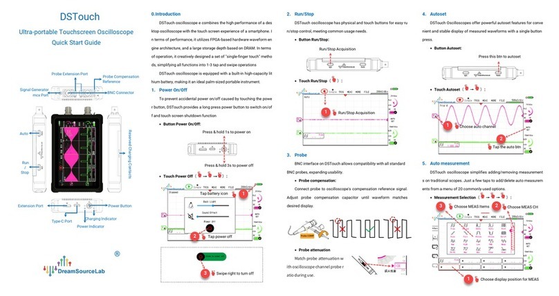
DreamSourceLab DSTouch User manual

1 www.dreamsourcelab.cn
DSTouch Oscilloscope
User Guide
V0.99

DSTouch User Guide
www.dreamsourcelab.cn 2
Revision History
Revision history:
Date (YY/MM/DD)
Version
Description
2023/05/23
V0.99
Added introduction to decoders and FFT.
2022/12/11
V0.98
Initial version.

DSTouch User Guide
3 www.dreamsourcelab.cn
Contents
CONTENTS ................................................................................................................................. 3
CHAPTER 1. INTRODUCTION.................................................................................................... 5
1.1 Overview..........................................................................................................................................................5
1.2 Basic Operations .............................................................................................................................................5
1.2.1 Power On/Off........................................................................................................................................................ 6
1.2.2 Charging................................................................................................................................................................ 6
1.2.3 User Interface ....................................................................................................................................................... 7
1.2.4 Run/Stop ............................................................................................................................................................... 7
1.2.5 Autoset.................................................................................................................................................................. 8
1.3 Probe Compensation .......................................................................................................................................9
1.4 Measure Signals ............................................................................................................................................10
1.4.1 Probe Settings ....................................................................................................................................................10
1.4.2 Connection..........................................................................................................................................................11
1.4.3 Grounding............................................................................................................................................................12
1.5 Precautions ...................................................................................................................................................13
1.5.1 Measurement Range ..........................................................................................................................................13
1.5.2 Withstand Voltage Range ..................................................................................................................................13
1.5.3 Probe Limitations ...............................................................................................................................................13
CHAPTER 2. OPERATION........................................................................................................ 15
2.1 Horizontal System .........................................................................................................................................15
2.1.1 Timebase ............................................................................................................................................................15
2.1.2 Roll.......................................................................................................................................................................16
2.1.3 Horizontal Position.............................................................................................................................................17
2.1.4 Storage Depth .....................................................................................................................................................18
2.1.5 Interpolation........................................................................................................................................................19
2.2 Vertical System .............................................................................................................................................20
2.2.1 Channel Settings.................................................................................................................................................20
2.2.2 Vertical Sensitivity ..............................................................................................................................................20
2.2.3 Vertical Offset.....................................................................................................................................................22
2.3 Trigger system ..............................................................................................................................................24
2.3.1 Trigger Position ..................................................................................................................................................24
2.3.2 Trigger Level .......................................................................................................................................................25
2.3.3 Trigger Modes ....................................................................................................................................................26
2.3.4 Trigger Source ....................................................................................................................................................27
2.3.5 Trigger Type........................................................................................................................................................27
2.3.6 Sensitivity............................................................................................................................................................28
2.3.7 Trigger Holdoff ...................................................................................................................................................29
2.4 Single Acquisition..........................................................................................................................................30
2.5 Quick Menu ...................................................................................................................................................30
2.6 Auto Measurements ......................................................................................................................................32
2.6.1 Vertical Measurements......................................................................................................................................33
2.6.2 Horizontal Measurements .................................................................................................................................33

DSTouch User Guide
www.dreamsourcelab.cn 4
2.6.3 Add/Delete Measurements................................................................................................................................34
2.7 Cursor Measurement .....................................................................................................................................35
2.7.1 H Bars..................................................................................................................................................................35
2.7.2 V Bars ..................................................................................................................................................................36
2.8 Display...........................................................................................................................................................36
2.8.1 X-Y Mode............................................................................................................................................................. 36
2.8.2 Persistence Mode............................................................................................................................................... 37
2.8.3 Clear Screen........................................................................................................................................................38
2.8.4 Grid Lines ............................................................................................................................................................ 38
2.9 Calibration .....................................................................................................................................................39
2.10 Signal Generator............................................................................................................................................41
2.10.1 Run/Stop ............................................................................................................................................................. 41
2.10.2 Frequency ...........................................................................................................................................................42
2.10.3 Amplitude............................................................................................................................................................42
2.10.4 Signal Type .........................................................................................................................................................43
2.11 Protocol Decoders .........................................................................................................................................43
2.11.1 Add/Delete Decoder ...........................................................................................................................................43
2.11.2 Decoder Results .................................................................................................................................................44
2.12 FFT ................................................................................................................................................................45
2.12.1 Parameter Settings.............................................................................................................................................45
2.12.2 Center Frequency ...............................................................................................................................................46
2.12.3 Frequency Range ................................................................................................................................................46
2.12.4 Spectrum Measurement ....................................................................................................................................47
2.13 File ................................................................................................................................................................48
2.13.1 Sessions..............................................................................................................................................................49
2.13.2 Screenshot and Gallery ......................................................................................................................................49
2.13.3 Disk Usage ..........................................................................................................................................................50
2.13.4 USB Mode ...........................................................................................................................................................50
2.13.5 Disk Format.........................................................................................................................................................50
2.14 System Settings ............................................................................................................................................51
2.14.1 Backlight and Sound ..........................................................................................................................................51
2.14.2 About...................................................................................................................................................................51
2.14.3 Language ............................................................................................................................................................52
CHAPTER 3. EXAMPLES ......................................................................................................... 53
3.1 Simple periodic signals..................................................................................................................................53
3.1.1 Acquisition: ......................................................................................................................................................... 53
3.1.2 Measurement......................................................................................................................................................53
3.2 Power Supply Ripple ......................................................................................................................................54
3.3 Crystal oscillator signal .................................................................................................................................55
3.3.1 Basic Setup .........................................................................................................................................................55
3.3.2 Trigger Setup ...................................................................................................................................................... 56
3.4 X-Y Function ..................................................................................................................................................56
3.5 Amplitude Modulated (AM) Wave ..................................................................................................................57

DSTouch User Guide
5 www.dreamsourcelab.cn
Chapter 1. Introduction
1.1 Overview
The DSTouch oscilloscope combines the high performance of a desktop oscilloscope with the touch screen
experience of a smartphone. In terms of performance, it utilizes FPGA-based hardware waveform engine
architecture, and a large storage depth based on DRAM. In terms of operation, it creatively designed a set of
"single-finger touch" methods, simplifying all functions into 1-3 tap and swipe operations
Furthermore, the DSTouch oscilloscope is equipped with a built-in high-capacity lithium battery, making it an
ideal palm-sized portable instrument
Main Features:
FPGA-based hardware waveform engine, ensuring no lag and ultra-high refresh rate.
DRAM-based large waveform buffer, with a maximum storage depth of up to 16Mpts.
Dual-channel input, with a real-time sampling rate of up to 1GSa/s and a maximum bandwidth of up to
150MHz.
4.3-inch IPS capacitive touchscreen, providing a smooth UI experience and convenient control logic.
Ultra-fast 1-second boot time, with one-click autoset of stable waveforms.
Multiple global configuration files can be saved and easily loaded with a single click.
Supports auto measurement of 20 parameters.
Built-in signal generator.
Supports adjustment of trigger sensitivity and hold-off time, meeting waveform capture requirements in
various scenarios.
Large-capacity lithium battery for extended battery life.
Supports user-side firmware upgrade operations.
Reserved rich function expansion interfaces.
Supports on-the-fly switching between Chinese and English language interfaces.
1.2 Basic Operations
The DSTouch oscilloscope has a compact size that fits perfectly in the palm of your hand
(129mmx77mmx20mm). The oscilloscope features a high screen-to-body ratio with a 4.3-inch IPS capacitive
touch screen on the front. On the side of the device, essential function buttons are retained, including the power
button on the left and the "Run/Stop" and "Auto" buttons at the top.
While ensuring its compactness, DSTouch uses the standard BNC interface commonly found in desktop
oscilloscopes. This enables the direct use of all standard probes with the DSTouch, ensuring stable and reliable
signal connections without compromising performance and stability due to its size. In addition to the input
channels, the DSTouch also integrates a signal generator function, with waveforms being output externally via
the MCX interface.
The DSTouch's USB port serves not only as a regular charging port but also allows for connections to a PC
for firmware upgrades or exporting various configurations and waveform screenshot files stored in the
oscilloscope. The DSTouch has also reserved multiple extend interface options through extend modules to meet
diverse measurement and debugging requirements in different scenarios.

DSTouch User Guide
www.dreamsourcelab.cn 6
Figure 1-1
1.2.1 Power On/Off
The DSTouch oscilloscope provides a "Long-Press Power On/Off" and "Touch-Controlled Shutdown" to
prevent accidental power toggling. In the power-off state, a 1-second long press of the power button turns the
device on, while in the power-on state, a long press of 3 seconds or more shuts it down.
Button Power On/Off:
Figure 1-2
1.2.2 Charging
The DSTouch oscilloscope is equipped with a built-in high-capacity lithium battery that can be charged
through the USB port located on the left side of the device. The charging input supports a maximum of 5V/2A. It
is important to ensure that the input voltage during charging does not exceed 5V, as higher voltages may
damage the instrument.
The DSTouch oscilloscope supports "Charge while using" functionality and features intelligent power
distribution to ensure that measurements are not affected during the charging process. In extreme cases, such
as battery damage, the DSTouch can also operate independently through external power supply.
During regular charging, the charging indicator light on the left side of the instrument remains a constant
Probe Calibration
Reference
Probe Extension Port
Charging Contacts
Charging Indicator
Power Indicator
USB Port
Expansion Port
Power Switch
Run/Stop
Auto
BNC Connector
Signal Generator
MCX Port
Shutdown state, press and hold for
1 second to power on
Power-on state, press and hold for
3 seconds to power off

DSTouch User Guide
7 www.dreamsourcelab.cn
red color. Once the charging is complete, the indicator light turns off. If the indicator light keeps flashing, it
indicates a charging malfunction.
Figure 1-3
1.2.3 User Interface
With the single-finger touch interface, the DSTouch oscilloscope allows users to effortlessly perform all
measurement operations. Through optimization of interaction, traditional multi-step operations on conventional
oscilloscopes can now be accomplished within just 1-3 touch gestures on this device.
Figure 1-4
1.2.4 Run/Stop
As the most frequently used feature, the DSTouch oscilloscope provides two methods for running and
stopping waveform acquisition: physical buttons and touch buttons.
DSTouch
Computer
Power adapter
Power bank
Vertical
Sensitivity
Channel 1
Label
Channel 0
Label
Automatic Measurement Display Area
Run/Stop
Function
Menu
Single Trigger
Enabled
Trigger position
Running state
Current waveform
position
Horizontal Timebase
Battery Display &
System Menu
Auto Setup
Channel Menu
Channel On/Of
Trigger level
Logo & Version
Information

DSTouch User Guide
www.dreamsourcelab.cn 8
Button Run/Stop:
Figure 1-5
Touch Run/Stop:
Figure 1-6
1.2.5 Autoset
The DSTouch oscilloscope offers both a physical "Auto" button and touch-controlled buttons to facilitate
autoset. When the user has not actively selected any channel, the autoset program will start detecting enabled
channels, beginning from Channel 0. It will then automatically designate the channel that first detects a
waveform transition as the active channel for autoset.
Alternatively, users can manually specify a channel for autoset by simply selecting the corresponding
channel as shown in Figure 1-8 and then initiating the autoset.
Button Auto:
Figure 1-7
Touch Auto:
Run/Stop Acquisition
Run/Stop
Acquisition
1
Auto Button

DSTouch User Guide
9 www.dreamsourcelab.cn
Figure 1-8
1.3 Probe Compensation
When using some probes such as 10X/100X attenuated probes, it is essential to ensure the oscilloscope's
input capacitance matches the probe's compensation capacitance to correctly measure AC signal waveforms.
Before the initial use of a specific probe on a new oscilloscope, it is necessary to adjust the probe's
compensation capacitance. The specific adjustment method is as follows:
1)Set the switch on the probe to 10X (or other desired attenuation setting) and connect it to the desired
channel of the oscilloscope. Connect the probe signal terminal to the probe compensation reference signal
(1KHz square wave), and the ground clip to the oscilloscope's ground terminal. Enable only the target channel on
the oscilloscope, and then click "Run" to initiate the Auto automatic setup.
Figure 1-9
2)The captured waveform on the oscilloscope is shown in Figure 1-10. If the waveform is found to be
improperly compensated, you can use the non-metallic adjustment tool to adjust the probe's variable
capacitance. Make adjustments until the waveform matches the correctly compensated waveform in the center.
1
2
Select Channel
Click "Auto"
Probe Compensation
Capacitor Position

DSTouch User Guide
www.dreamsourcelab.cn 10
Figure 1-10
1.4 Measure Signals
1.4.1 Probe Settings
The DSTouch oscilloscope comes equipped with a standard BNC interface, making it compatible with
various types of BNC probes. To accommodate different probe attenuation ratios, the DSTouch oscilloscope
offers attenuation adaptation settings ranging from 0.1X to 1000X (in 1-2-5 steps).
Users need to select the right probe ratio based on the actual attenuation ratio of the currently connected
probe, and then oscilloscope will show accurate measurement results.
For example, as shown in Figure 1-11, when using a 10X probe, simply set the probe ratio to 10X in the UI
settings.
Figure 1-11
Except the single-ended passive probes, users can also use differential probes for measuring differential
signals. Additionally, users have the option to employ current probes for testing current signals. The DSTouch
oscilloscope supports the switching between voltage and current display.
Insufficient compensation
Correct compensation
Excessive compensation

DSTouch User Guide
11 www.dreamsourcelab.cn
Figure 1-12
1.4.2 Connection
When measuring signals, it is crucial to ensure that the reference ground of the measured signal is
connected as closely as possible to the oscilloscope probe's ground terminal. As the DSTouch oscilloscope is
powered by a battery, it offers greater flexibility in grounding compared to desktop oscilloscopes that rely on
mains power. When not connected to the mains for charging, the DSTouch oscilloscope functions as a handheld
device. Its ground terminal can follow the reference potential of the measured system without concerns about
short circuits between different ground potentials, thus avoiding any potential damage to equipment or
instruments.
Certainly, this does not mean that the ground terminal can be connected arbitrarily. For example, when
using a single-ended probe for measurements, it is recommended to connect the ground terminal to a
voltage-stable reference plane and avoid connecting it to a reference point with high noise or continuous voltage
fluctuations. This reduces interference with the oscilloscope itself and ensures more accurate measurement
results. If the measured system cannot find a reliable reference plane, it is recommended to use a differential
probe for measurements.
Figure 1-13
1
2
Select the dial of the
channel being connected
Swipe up and down within
this area to select the
attenuation ratio

DSTouch User Guide
www.dreamsourcelab.cn 12
1.4.3 Grounding
There are mainly two ways to ground the probe: one is by using a clip, and the other is through a ground
spring. The main difference between these two methods lies in the size of the loop area formed between the
signal and the ground terminal. The larger the loop area, the more spatial electromagnetic waves pass through it,
making the signal more susceptible to interference when entering the oscilloscope.
As shown in Figure 1-14, when using a ground spring, the loop area formed between the signal and the
ground terminal is much smaller compared to the one formed when using a clip.
Figure 1-14
Figure 1-15 shows the waveform obtained when the grounding is done properly, indicating a clean and
accurate signal measurement. On the other hand, Figure 1-16 illustrates a typical waveform when the ground
loop area is too large, causing the measured signal to be interfered with and resulting in distorted or noisy
measurements.
Figure 1-15

DSTouch User Guide
13 www.dreamsourcelab.cn
Figure 1-16
1.5 Precautions
1.5.1 Measurement Range
The measurement range of an oscilloscope refers to the maximum observable signal range at a fixed probe
attenuation ratio. The vertical sensitivity range of the DSTouch oscilloscope is 10mV/div to 5V/div, with a total
of 8 divisions in the vertical direction. When using a 1X probe, the measurement range is -20V to +20V with a 0V
offset. By adjusting the vertical offset setting, the measurement range can be changed to 0V to +40V or -40V to
0V. The maximum peak-to-peak voltage measurable with a 1X probe is 40V.
When using a 10X probe, the measurement range with a 0V offset is extends to -200V to +200V. This is
because the 10X probe attenuates the input signal by 10 times before it is fed into the oscilloscope. Similarly,
when using a 100X probe, the measurement range with a 0V offset becomes -2KV to +2KV.
1.5.2 Withstand Voltage Range
The voltage withstand range of an oscilloscope refers to the input voltage range that the oscilloscope's
input terminals (excluding the probe) can withstand without causing damage to the oscilloscope itself. The
DSTouch oscilloscope has a voltage withstand range of -200V to +200V (peak-to-peak). This means that when
using a 1X probe to input voltage within the range of -200V to +200V or using a 10X probe to input voltage within
the range of -2000V to +2000V, the oscilloscope will not be damaged.
The voltage withstand range of the DSTouch oscilloscope is designed to be 10 times the measurement
range under the same conditions. For common 1X and 10X adjustable probes, even if the wrong attenuation
ratio is accidentally selected, as long as the input voltage is within the -200V to +200V range, there is no need to
worry about damaging the oscilloscope.
For measuring high voltage signals (peak values exceeding ±200V), it is recommended to use 100X or
higher high-voltage probes to ensure user safety. Alternatively, users can choose high-attenuation differential
probes to eliminate the limitations of single-ended probe grounding.
1.5.3 Probe Limitations
The bandwidth of the probe itself can significantly impact the measurement performance. It is generally

DSTouch User Guide
www.dreamsourcelab.cn 14
recommended to choose a probe with a bandwidth greater than the oscilloscope's own bandwidth for
high-frequency measurements to fully leverage the oscilloscope's capabilities. For common 1X and 10X
adjustable probes, it is crucial to be aware that under the 1X setting, the probe's own bandwidth is typically only
around 6MHz, making it suitable for observing low-frequency small signals like power supply ripples. Please
refrain from using a 1X probe for high-frequency signals.
For example, when measuring high-frequency digital signals ranging from 0V to 3.3V, a high-bandwidth 10X
probe should be used with the vertical sensitivity set to 1V/div for optimal results.

DSTouch User Guide
15 www.dreamsourcelab.cn
Chapter 2. Operation
The portability of the DSTouch oscilloscope is not only reflected in its appearance and size but also in its
optimized user interface. DSTouch has defined a complete set of "single-finger touch" operation methods. All
functions are simplified to 1-3 steps of tapping and sliding, eliminating the need to search for buttons and
menus, making it more convenient for users to perform quick measurements, debugging, and problem
localization challenges.
2.1 Horizontal System
The oscilloscope's horizontal system controls all variables related to the time domain during the data
acquisition process. These variables include the horizontal timebase, mode, position, interpolation, and storage
depth, among others.
2.1.1 Timebase
The horizontal timebase directly determines the duration of the waveform that the oscilloscope can observe.
For example, with a timebase of 1μs/div, a 10-division horizontal direction on the oscilloscope represents a time
window of 10μs; when the timebase is set to 1s/div, the observation window represents 10s of time. To observe
waveforms of different frequencies, an appropriate horizontal timebase needs to be set.
The three main parameters that determine the oscilloscope's waveform acquisition process, namely
acquisition duration, storage depth, and sampling rate, must satisfy the following equation:
In the implementation of the oscilloscope, the waveform storage space is limited by the hardware storage
depth for each acquisition. The acquisition duration is determined by the user-set horizontal timebase. Therefore,
when the user changes the horizontal timebase, the oscilloscope automatically selects the maximum available
sampling rate as the current actual sampling rate based on the equation above. This principle also illustrates
how the storage depth affects the real performance of an oscilloscope.
The DSTouch oscilloscope offers various methods to adjust the horizontal timebase. The simplest way
requires just one click. In the default state of the oscilloscope, clicking on the upper or lower half of the
waveform area on the screen allows for single-step increase/decrease of the horizontal timebase (in 1-2-5
steps). The specific operation process is shown in Figure 2-1.

DSTouch User Guide
www.dreamsourcelab.cn 16
Figure 2-1
When you need to use other adjustment methods, you can click on the horizontal timebase menu located in
the top right corner of the screen. This action will reveal a scroll wheel on the left side of the screen, indicating
that you have entered the horizontal timebase adjustment mode.
Slide Adjustment: You can quickly change the timebase by sliding up or down in the scroll wheel area or the
waveform area. Sliding upwards increases the timebase, while sliding downwards decreases it. The scroll wheel
area also supports inertia setting, which means that when you slide your finger quickly on the scroll wheel, it will
rapidly adjust the timebase to the maximum/minimum value through inertia. After performing a sliding operation,
a single click will stop the inertia operation of the scroll wheel. Refer to Figure 2-2 for a visual representation of
this process.
Figure 2-2
Single-step adjustment: Above and below the scroll wheel, there are buttons that allow for single-step
timebase adjustment. Clicking the upper button increases the timebase by one step, and clicking the lower
button decreases the timebase by one step.
2.1.2 Roll
The normal display mode of an oscilloscope is commonly referred to as Y-T mode, where the vertical axis (Y)
represents voltage, and the horizontal axis (T) represents time. The default acquisition and display process is
based on one frame of waveform as a fundamental unit. It can be simplified as follows: the oscilloscope
acquires one frame of waveform, processes it through the processing unit, and displays it on the screen. It then
proceeds to acquire the next waveform and repeats the process. When the horizontal timebase is relatively
1
Single click to increase
the timebase
single click to decrease
the timebase
1
2
Single-finger up or
down swipe
Single-step increase/decrease
of the timebase
2

DSTouch User Guide
17 www.dreamsourcelab.cn
small, the time taken to acquire one frame of waveform is very short, allowing us to observe dynamic changing
waveforms on the oscilloscope.
However, when users set a larger horizontal timebase, the time taken to acquire one frame of waveform
may become quite long. For example, when the timebase is set to 1s/div, it takes 10 seconds to acquire one
frame of waveform. If displayed in Y-T mode, we would only see one frame of waveform every 10 seconds.
Therefore, in situations where a large timebase is set, it is more convenient to use the ROLL mode to observe the
waveform. As shown in Figure 2-3, in roll mode, the waveform is dynamically displayed on the screen as time
progresses, without waiting for one frame to be filled before displaying it. When the waveform fills the entire
window, it will scroll from right to left, continuously displaying the most recently acquired waveform on the right
side.
Figure 2-3
The DSTouch oscilloscope will automatically switch between Y-T mode and roll mode based on the user's
current horizontal timebase settings. When the timebase is <50ms/div, it operates in Y-T mode. When the
timebase is >=50ms/div, it automatically enters scroll mode.
If the "Auto" trigger is set, Y-T mode will prioritize displaying waveforms that meet the trigger conditions.
Only when there is no triggered waveform, it will automatically display the current waveform. In roll mode with
"Auto" trigger, it will continuously display the current waveform without considering the trigger conditions.
If you need to force trigger the display in roll mode, you can set the trigger type to "Normal." This will return
the waveform display to Y-T mode, capturing waveforms that meet the trigger conditions and displaying them on
the screen after acquiring at least one frame of waveform.
2.1.3 Horizontal Position
The DSTouch oscilloscope supports ultra-long storage depth, allowing users to capture waveforms and then
zoom in, observe, and locate any part of the entire storage depth after the acquisition has stopped. By moving
the current display window, the DSTouch oscilloscope can position any sampling point from the entire storage
depth at the center of the waveform window. Coupled with the horizontal timebase scaling operation, users can
observe any sampling point position waveform at any desired zoom level. The relationship between the
horizontal window position and the waveform of the entire storage depth is illustrated as follows.
Automatically entering the scrolling
mode based on the timebase

DSTouch User Guide
www.dreamsourcelab.cn 18
The entire waveform of
the storage depth
The movable range of the waveform window
The current position of
the waveform window
T
Move the window to
the leftmost position
Move the window to
the trigger position
Move the window to
the rightmost position
Figure 2-4
The DSTouch oscilloscope's interface includes a simple graphical representation of the relationship
between the display window and the storage depth. A long bar below the horizontal timebase represents the
entire stored waveform, with the green portion indicating the current position of the waveform window. The
specific method for moving the waveform window is as follows:
Single-finger swipe: In the default display mode, simply swipe left or right with a single finger on the
waveform window to move the position of the horizontal window. When combined with the single-tap zoom
function for the timebase in this mode, it becomes very convenient to locate any waveform within the storage
depth, enabling users to zoom in and observe specific regions of the waveform.
Figure 2-5
Quick positioning: While sliding the horizontal window position, three quick buttons will appear above the
window. From left to right, these buttons allow users to quickly position the waveform to the far-left, trigger
position, or far-right of the display window's center position.
2.1.4 Storage Depth
The storage depth of conventional oscilloscopes is generally a fixed value, limited by the hardware
memory's maximum capacity. In contrast, the DSTouch oscilloscope provides a large hardware storage depth
and also allows users to set the storage depth at the software level, emulating different oscilloscopes with
varying storage depths to better accommodate diverse waveform observation needs.
1
Swipe left or right
on the screen
Single-click to
quickly locate
2

DSTouch User Guide
19 www.dreamsourcelab.cn
Reducing the storage depth drastically reduces the amount of data the oscilloscope needs to process, while
it may also lower the effective sampling rate under certain horizontal timebase settings. The process of
changing the storage depth settings on the DSTouch oscilloscope is illustrated in Figure 2-6.
Figure 2-6
2.1.5 Interpolation
The DSTouch oscilloscope provides two different waveform interpolation algorithms. The linear
interpolation method connects the sampled points with straight lines, making it more suitable for reconstructing
signals with sharp edges, and is ideal for observing square wave signals. The sine interpolation method, on the
other hand, reconstructs the sampled points using sine wave signals, which is more suitable for observing
sinusoidal signals. Considering the frequency response characteristics of electrical signal transmission in the
real world, most signals better conform to sinusoidal characteristics, making the sine interpolation method more
widely used.
As shown in Figure 2-7, you can switch between different interpolation algorithms by selecting the
corresponding radio button in the settings window.
Figure 2-7
1
2
3
Swipe left or right to select
the storage depth
1
2
3

DSTouch User Guide
www.dreamsourcelab.cn 20
2.2 Vertical System
The vertical system of the oscilloscope mainly controls and sets parameters related to the channels.
2.2.1 Channel Settings
The DSTouch oscilloscope is designed with separate operating interfaces for each channel. As shown in
Figure 2-8, you can click on the respective channel to open the corresponding channel's settings window.
Figure 2-8
Channel On/Off: In the default state, you can directly click the toggle button below the channel to on/off the
corresponding channel. Alternatively, you can open the channel settings window first and then click the central
toggle button to switch the channel status.
Color: It supports channel waveform color settings to better distinguish or highlight signals from different
channels.
Bandwidth: You can switch between 20MHz bandwidth limit and full bandwidth. If you want to reduce signal
noise or observe low-frequency signals, you can use the bandwidth limit.
Units: It supports switching between voltage and current units to match the type of probe being used.
Coupling: You can switch between AC and DC coupling modes.
Probe Ratio: It supports selecting different probe ratios to match different probe attenuations.
2.2.2 Vertical Sensitivity
Vertical sensitivity determines the range and accuracy of the oscilloscope in the vertical direction, and its
specific value represents how much voltage/current one grid in the vertical direction represents. To achieve
more accurate measurements, and within the range, the vertical sensitivity should be set to make the measured
signal occupy more vertical grids. For example, when measuring a +-3V sine wave signal, a vertical sensitivity of
1V/Div is a better choice compared to 5V/Div. The vertical sensitivity of the DSTouch oscilloscope uses a "1-2-5"
step scale, and the specific setting method is as follows:
Quick Operation: Click the vertical sensitivity label of the corresponding channel to select the channel you
want to set. Once selected, the label starts to flash. At this time, you can change the vertical sensitivity of the
corresponding channel by sliding up and down within the waveform area. Alternatively, you can also click on the
Waveform color
selection
Single-click to open
channel options
Bandwidth limit
selection
Voltage/Current
display toggle
DC/AC coupling
switch
Probe attenuation
selection
Channel switch
1
Other manuals for DSTouch
1
Table of contents
Other DreamSourceLab Test Equipment manuals