Dresser Consolidated 1900 User manual

Consolidated
INSTALLATION, OPERATION
AND MAINTENANCE MANUAL
Consolidated Safety Relief Valve
Type 1900
Industrial Valve Operation
Dresser Valve and Controls Division
Alexandria, Louisiana 71309-1430 (USA)
®
Design Options
Include:
Bellows
(-30),
O-Ring Seat
(DA),
Liquid Trim
(LA)
and
Thermodisc
®
(TD)
®
CON-2
Revised 7/97

CON-2
Product Safety Sign and Label System
If and when required, appropriate safety labels have
been included in the rectangular margin blocks
throughout this manual. Safety labels are vertically
oriented rectangles as shown in the
representative
examples
(below),consistingofthreepanelsencircled
by a narrow border. The panels can contain four
messages which communicate:
• The level of hazard seriousness.
• The nature of the hazard.
• The consequence of human, or product, interaction
with the hazard.
• The instructions, if necessary, on how to avoid the
hazard.
The top panel of the format contains a signal word
(DANGER, WARNING, or CAUTION) which
communicates the level of hazard seriousness.
The center panel contains a pictorial which
communicatesthenatureofthehazard,andthepossible
consequence of human or product interaction with the
hazard.Insomeinstancesofhumanhazardsthepictorial
may,instead,depictwhatpreventivemeasurestotake,
such as wearing protective equipment.
The bottom panel may contain an instruction message
on how to avoid the hazard. In the case of human
hazard, this message may also contain a more precise
definition of the hazard, and the consequences of
human interaction with the hazard, than can be
communicated solely by the pictorial.
DANGER
Do not remove bolts if
pressure in line,as this
will result in severe
personal injury or death.
Know nuclear health
physics procedures, if
applicable, to avoid
possible severe per
sonal
injury or death.
WARNING
Wear necessary
protective equipment
to prevent possible
injury.
CAUTION
SAFETY ALERTS!
READ –UNDERSTAND –PRACTICE
1. DANGER: High temperature/pressure can
causeinjury. Be sure all systempressureisabsent
before repairing or removing valves.
2. DANGER: Don’t stand in front of valve
outletwhendischarging.STANDCLEAROFVALVE
to prevent exposure to trapped, corrosive media.
3. DANGER: When inspecting a pressure
relief valve for leakage, BE VERY CAREFUL!
DANGER
Do not remove bolts if
pressure in line,as this
will result in severe
personal injury or death.

CON-2
Page 1
Contents
Section Subject Page
Product Safety Sign and Label System..................................................................... Inside Front Cover
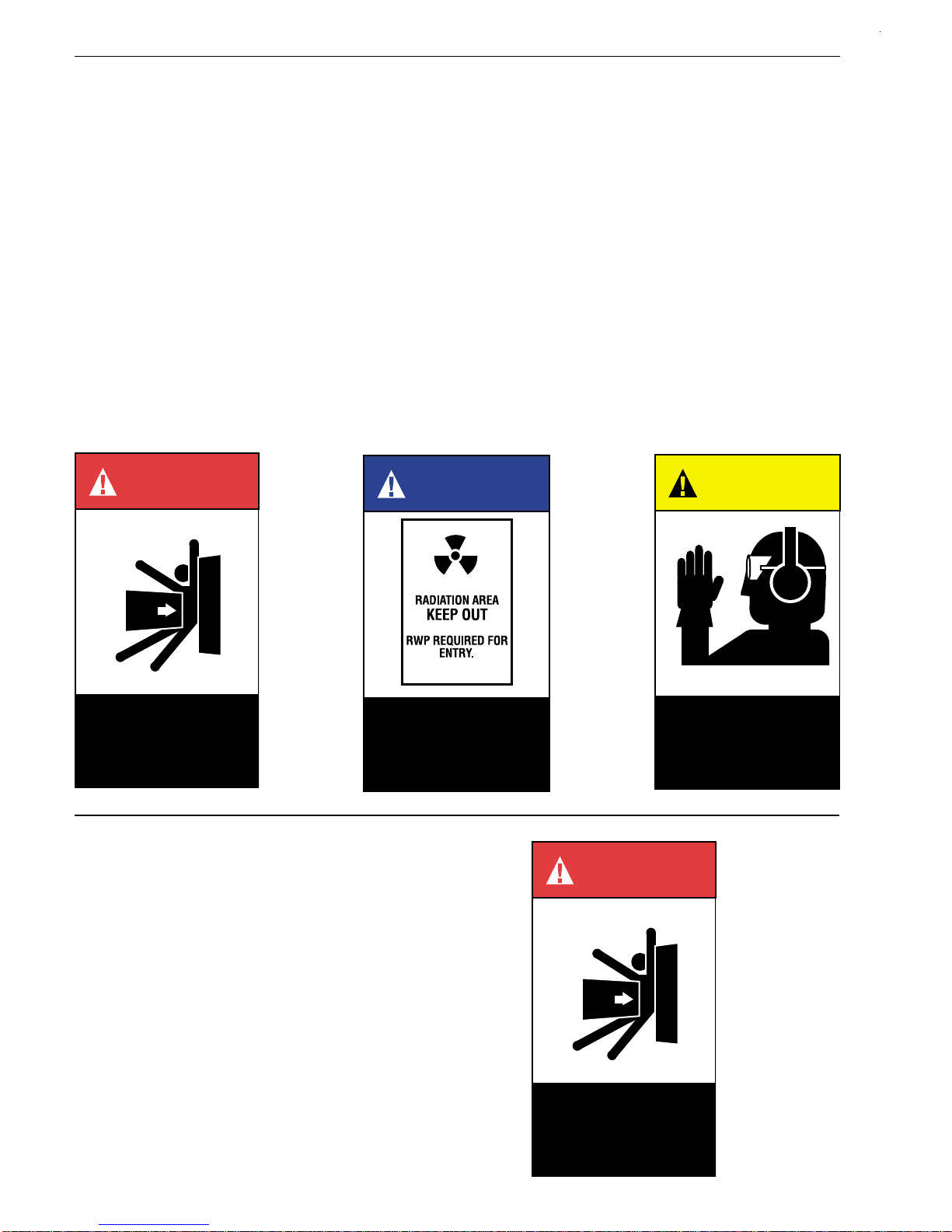
I. Safety Alerts .................................................................................................................................. 2
II. Terminology for Safety Relief Valves ............................................................................................ 4
III. Introduction ................................................................................................................................... 5
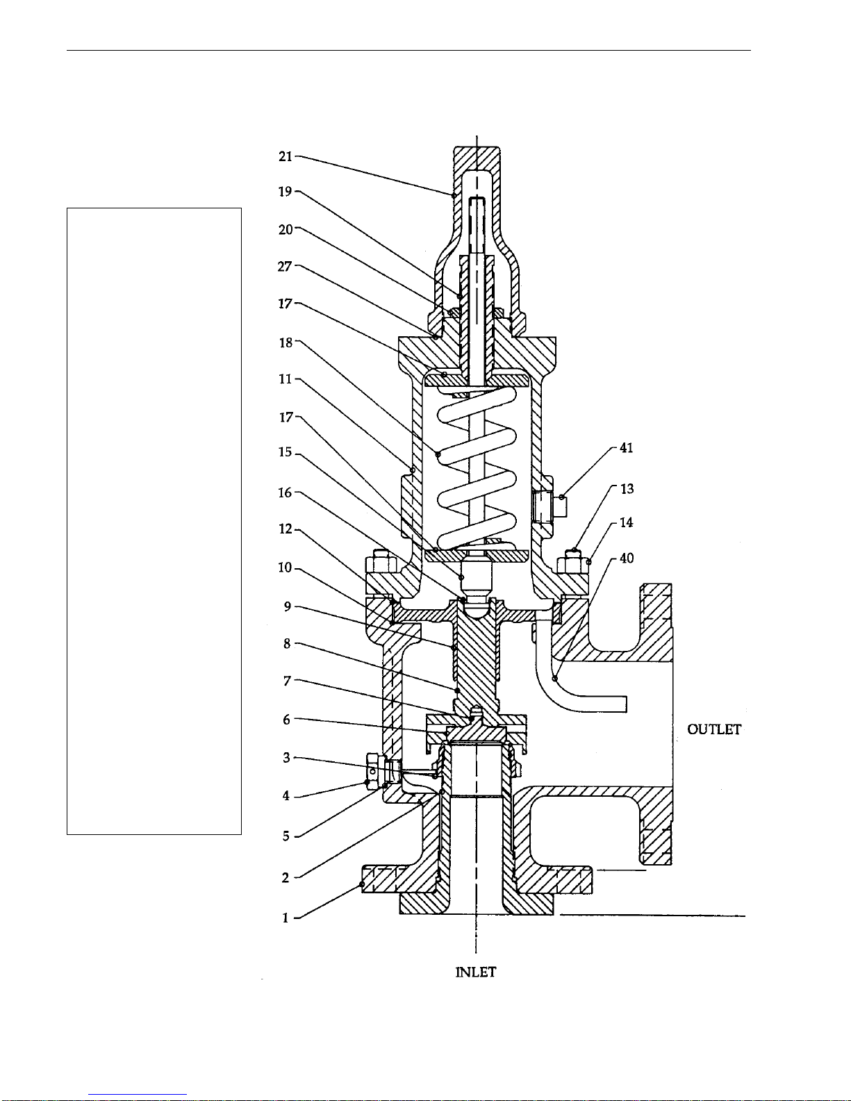
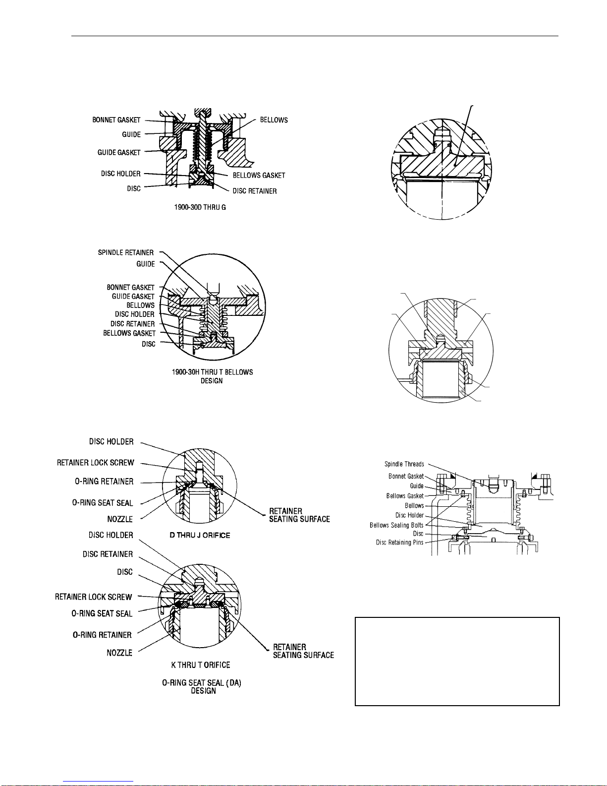
IV. Design Features and Nomenclature .............................................................................................5
V. Handling, Storage and Pre-Installation ......................................................................................... 8
VI. Recommended Installation Practices ............................................................................................ 9
A. Mounting Position ................................................................................................................ 9
B. Inlet Piping ........................................................................................................................... 9
C. Outlet Piping ........................................................................................................................ 11
VII. Disassembly Instructions .............................................................................................................. 12
A. General Information ............................................................................................................. 12
B. Specific Steps ...................................................................................................................... 12
VIII. Cleaning ........................................................................................................................................ 14
IX. Parts Inspection ............................................................................................................................ 14
A. Nozzle.................................................................................................................................. 14
B. Nozzle Seat Width ............................................................................................................... 16
C. Nozzle Bore ......................................................................................................................... 16
D. 1900, 1900-30 Standard Disc .............................................................................................. 16
E. 1900 Series Thermodisc...................................................................................................... 17
F. Disc Holder .......................................................................................................................... 18
G. Guide ................................................................................................................................... 21
H. Spindle................................................................................................................................. 21
I. Spring .................................................................................................................................. 21
X. Maintenance Instructions .............................................................................................................. 22
A. General Information ............................................................................................................. 22
B. Lapping Nozzle Seats (Non O-Ring Styles) ........................................................................ 22
C. Nozzle Seat Widths-Lapped ................................................................................................ 22
D. Lapping Disc Seats.............................................................................................................. 24
E. Precautions and Hints for Lapping Seats ............................................................................ 24
F. Lapping O-Ring Seating Surfaces ....................................................................................... 24
G. Reconditioning of Laps ........................................................................................................25
H. Remachining Nozzle Seats and Bores ................................................................................ 25
I. Remachining the Disc Seat ................................................................................................. 26
J. Checking Spindle Concentricity ........................................................................................... 27
K. Set Pressure Change-Disc Holder ...................................................................................... 28
L. Checking Lift on Restricted Lift Valves ................................................................................ 28
XI. Reassembly................................................................................................................................... 29
A. General Information ............................................................................................................. 29
B. Lubrication ........................................................................................................................... 30
C. Specific Steps ...................................................................................................................... 30
XII. Setting and Testing ....................................................................................................................... 35
A. General Information ............................................................................................................. 35
B. Test Equipment ................................................................................................................... 35
C. Test Media ........................................................................................................................... 35
D. Setting the Valve ................................................................................................................. 35
E. Set Pressure Compensation................................................................................................ 35
F. Seat Tightness Testing ........................................................................................................37
XIII. Hydrostatic Testing and Gagging .................................................................................................. 38
XIV. Manual Popping of the Valve ........................................................................................................ 39
XV. Conversion of Type 1900 Flanged Safety Relief Valves
From Conventional to Bellows Type, and Vice Versa ................................................................... 40
A. General Information ............................................................................................................. 40
B. Conversion From Conventional to Bellows Type................................................................. 41
C. Conversion From Bellows to Conventional Type................................................................. 41
XVI. Trouble Shooting Type 1900 Valves ............................................................................................. 42
XVII. Maintenance Tools and Supplies .................................................................................................. 42
XVIII. Replacement Parts Planning......................................................................................................... 44
A. Basic Guidelines .................................................................................................................. 44
B. Replacement Parts List ....................................................................................................... 44
C. Identification and Ordering Essentials ................................................................................. 44
XIX. Genuine Dresser Parts.................................................................................................................. 45
XX. Recommended Spare Parts for the 1900 Safety Relief Valves .................................................... 46
XXI. Manufacturer's Warranty, Field Service & Repair Program .......................................................... 48
A. Warranty Information ........................................................................................................... 48
B. Field Service ........................................................................................................................ 48
C. Factory Repair Facilities ...................................................................................................... 48
D. Safety Relief Valve Maintenance Training........................................................................... 48
Appendix RE: Optional Glide-Alloy® Parts ................................................................................... A.1
Service Engineers and Sales Office Locations ......................................................... Back Cover

CON-2
Page 2
SAFETY ALERTS!
READ –UNDERSTAND –PRACTICE
1. WARNING: Allow the system to cool to
room temperature before cleaning, servicing or
repairing the system. Hot components or fluids
can cause severe personal injury or death.
2. WARNING: Always read and comply with
safety labels on all containers. Do not remove or
deface the container labels. Improper handling or
misuse could result in severe personal injury or
death.
3. WARNING: Never use pressurized
fluids/gas/airtocleanclothingorbodyparts.Never
use body parts to check for leaks or flow rates or
areas. Pressurized fluids/gas/air injected into or
nearthebodycancauseseverepersonalinjuryor
death.
4. WARNING: It is the responsibility of the owner
tospecifyandprovideguardingtoprotectpersons
from pressurized or heated parts. Contact with
pressurized or heated parts can result in severe
personal injury or death.
5. WARNING: Do not allow anyone under
theinfluenceofintoxicants ornarcoticstoworkon
or around pressurized systems. Workers under
the influence of intoxicants or narcotics are a
hazard both to themselves and other employees
and can cause severe personal injury or death to
themselves or others.
6. WARNING: Incorrect service and repair
could result in product or property damage or
severe personal injury or death.
WARNING
All potential hazards may
not be covered in this
manual.
WARNING
Improper tools or
improper use of right
tools could result in
personal injury or
product damage.
WARNING
Improper use or repair of
pressurized media or
steam device may result
in severe personal injury
or death.
WARNING
Heed all container label
warnings.
WARNING
Provide and use guarding
to prevent contact with
heated and/or
pressurized parts
WARNING
Do not work with valves
while under the
influence of intoxicants
or narcotics.
7. WARNING: These WARNINGS are as
complete as possible but not all-inclusive. Dresser
cannot know all conceivable service methods nor
evaluate all potential hazards.
8. WARNING: Use of improper tools or
improper use of right tools could result in personal
injury or product or property damage.
9. WARNING:Somevalveproductsmanufacturedby
DVCD may be used in radioactive environments.
Consequently, prior to starting any operation in a
radioactiveenvironment,theproper“healthphysics”
procedures should be followed, if applicable.

CON-2
▲
Page 3
Know nuclear health
physics procedures, if
applicable, to avoid
possible severe per
sonal
injury or death.
WARNING
Wear necessary
protective equipment
to prevent possible
injury.
CAUTION
CAUTION
Heed all service manual
warnings.Read
installation instructions
before installing valve(s).
1. CAUTION: Heed all service manual warnings.
Read installation instructions before installing
valve(s).
2. CAUTION: Wear hearing protection when testing
or operating valves.
3. CAUTION: Wear appropriate eye and clothing
protection.
4. CAUTION: Wear protective breathing apparatus
to protect against toxic media.
NOTE:
Any service questions not covered in this manual
shouldbereferredtoDresser’sServiceDepartment,
Phone (318) 640-6055.

CON-2
Page 4
II. Terminology for Safety
Relief Valves
•Accumulation
Accumulation is the pressure increase over the
maximum allowable working pressure of the
vessel during discharge through the pressure
relief valve, expressed as a percentage of that
pressure, or actual pressure units.
•Back Pressure
Back pressure is the pressure on the discharge
side of a safety relief valve:
1. Superimposed Back Pressure
Superimposedbackpressureisthepressure
in the discharge header before the safety
relief valve opens.
a) Constant-Specifysingleconstantback
pressure (e.g., 20 psig/1.38 bar).
b) Variable - Specify variable back
pressure range using min. and max.
limits (e.g., 0 to 20 psig/1.38 bar).
2. Built-up Back Pressure
Built-up back pressure is pressure which
develops at the valve outlet as a result of
flow, after the safety relief valve has been
opened.
•Blowdown
Blowdownisthedifferencebetweensetpressure
andreseatingpressureofapressurereliefvalve,
expressedasapercentageofthesetpressure,or
actual pressure units.
•Cold Differential Set Pressure
Cold differential set pressure is the pressure at
which the valve is adjusted to open on the test
stand. Thispressure includesthecorrections for
back pressure and/or temperature service
conditions.
•Differential Between Operating and Set
Pressures
Valvesin processservicewill generallygivebest
resultsiftheoperatingpressuredoesnotexceed
90%of theset pressure. However, onpump and
compressor discharge lines, the differential
requiredbetweentheoperatingandsetpressures
may be greater because of pressure pulsations
coming from a reciprocating piston. It is
recommended that the valve be set as high
above the operating pressure as possible.
•Lift
Lift is the actual travel of the disc away from the
closed position when a valve is relieving.
•Maximum Allowable Working Pressure
Maximum allowable working pressure is the
maximumgaugepressurepermissibleinavessel
at a designated temperature. A vessel may not
beoperatedabovethispressure,oritsequivalent,
at any metal temperature other than that used in
its design. Consequently, for that metal
temperature, it is the highest pressure at which
the primary pressure safety relief valve is set to
open.
•Operating Pressure
The operating pressure is the gauge pressure to
whichthevesselisnormallysubjectedinservice.
A suitable margin is provided between operating
pressure and maximum allowable working
pressure. For assured safe operation, the
operatingpressure shouldbeat least10% under
themaximumallowableworkingpressureor5psi
(.34 bar), whichever is greater.
•Overpressure
Overpressureisapressureincreaseover theset
pressure of the primary relieving device.
Overpressure is similar to accumulation when
the relieving device is set at the maximum
allowable working pressure of the vessel.
Normally, overpressure is expressed as a
percentage of set pressure.
•Rated Capacity
Rated capacity is the percentage of measured
flow at an authorized percent overpressure
permittedbytheapplicablecode. Ratedcapacity
is generally expressed in pounds per hour (lb/hr)
forvapors;standardcubicfeetperminute(SCFM)
or m3/min for gases; and in gallons per minute
(GPM) for liquids.
•Relief Valve
A relief valve is an automatic pressure-relieving
device, actuated by static pressure upstream
from the valve, a relief valve is used primarily for
liquid service.
•Safety Relief Valve
A safety relief valve is an automatic pressure-
relieving device which may be used as either a
safetyorreliefvalve,dependinguponapplication.
A safety relief valve is used to protect personnel
and equipment by preventing excessive
overpressure.

CON-2
Page 5
II. (Continued)
•Safety Valve
Asafety valve is an automatic pressure-relieving
device actuated by the static pressure upstream
ofthevalve,andcharacterized by rapid opening
or pop action. It is used for steam, gas or vapor
service.
•Set Pressure
Set pressure is the gauge pressure at the valve
inlet,forwhichtherelief valve has been adjusted
toopenunderserviceconditions. Inliquidservice,
set pressure is determined by the inlet pressure
at which the valve starts to discharge. In gas or
vapor service, the set pressure is determined by
the inlet pressure at which the valve pops.
•Simmer
Simmer is characterized by the audible passage
ofagasorvaporacrosstheseating surfacesjust
prior to "pop". The difference between this "start
toopenpressure"andthesetpressureissimmer,
andisgenerallyexpressedasapercentageofset
pressure.
•Valve Trim
Valve trim includes the nozzle and disc.
III. Introduction
A safety relief valve is an automatic pressure actuated
relievingdevicesuitableforuseeither asa safetyvalve
or relief valve, depending on application.
Safety relief valves are used on hundreds of different
applications, including liquids and hydrocarbons;
therefore, the valve is designed to meet many
requirements. The 1900 series valves included in this
manual can
only
be used to meet Section VIII
requirements. It cannot be used on ASME Code
Section I steam boilers or superheaters, but may be
used on process steam.
IV. Design Features and
Nomenclature
•Cap and Lever Interchangeability
Many times it is necessary to change the type of
cap or lever in the field after a valve has been
installed. All flanged Consolidated®Safety Relief
Valves are designed so they can be converted to
anytypeofleverorcapdesired. Itisnotnecessary
to remove the valve from the installation, nor will
the set pressure be affected when making such a
change.
•Design Simplicity
ConsolidatedSafetyReliefValveshaveaminimum
number of component parts. This results in a
savings by minimizing spare parts inventory and
simplifies valve maintenance.
•Nomenclature Related to Design Features
Applicable nomenclature of the components of
Type 1900 valves, including those with design
optionsforbellowsO-Ringseat,andliquidtrimand
Thermodisc, is identified in Figures 1 thru 6 on
pages 6 and 7.
•Simple Blowdown Adjustment
The Consolidated single blowdown ring design
makes it possible to set and test a valve that has
been in service when it cannot be set on line and
mustbetakentothecustomer'sshop. Theringcan
bepositionedsothatthesetpointcanbeobserved
although the volume of the testing media is very
low. After the set pressure has been established,
proper blowdown can be attained by merely
positioningtheringinaccordancewiththeadjusting
ringpositionshowninTables12-14(asappropriate),
on page 34 of this manual.
•Valve Interchangeability
A Standard Consolidated Safety Relief Valve may
be converted to the bellows type, the O-Ring seat
seal type, etc. and vice versa. This requires a
minimumnumberofnewparts,andresultsinlower
costs should conversion be required.

CON-2
Page 6
Part
No. Nomenclature
1 Base
2 Nozzle
3 Adjusting Ring
4 Adjusting Ring Pin
5 Adj. Ring Pin Gasket
6 Disc
7 Disc Retainer
8 Disc Holder
9 Guide
10 Guide Gasket
11 Bonnet
12 Bonnet Gasket
13 Base Stud
14 Stud Nut
15 Spindle
16 Spindle Retainer
17 Spring Washer
18 Spring
19 Adjusting Screw
20 Adjusting Screw Nut
21 Screwed Cap
*22 Bolted Cap
*23 Packed Cap
*24 Plain Cap
*25 Cap Bolt
*26 Cap Set Screw
27 Cap Gasket
*28 Release Nut
*29 Release Locknut
*30 Lever
*31 Lifting Fork
*32 Lever Shaft
*33 Packing
*34 Packing Nut
*35 Top Lever
*36 Drop Lever
40 Eductor Tube
41 Bonnet Vent Plug
* Shown in Figures 38-42 on
page 39 of this manual.
FIGURE 1
CONSOLIDATED SAFETY RELIEF VALVE
TYPE 1900 - CONVENTIONAL

CON-2
NOTE:
A combination of the O-Ring seat
sealandliquidtrimdesignoptionsis
designated as DA-LA.
FIGURE 4
FIGURE 6
V & W Orifice Only
FIGURE 2
Page 7
DESIGN OPTIONS
THERMODISC (TD)
DESIGN
FIGURE 3
THERMODISC
FIGURE 5
LA Liquid Trim Design
(See Fig. 20)
DISC RETAINER
DISC
GUIDE
ADJUSTING RING
NOZZLE
DISC HOLDER
PART INTEGRITY
ESPECIALLY DESIGNED
FOR SHORT BLOWDOWN
AND SMOOTH CHATTER-
FREE OPERATION
AT MAXIMUM CAPACITY.

CON-2
Page 8
V. Handling, Storage and
Pre-Installation
•Handling
A flanged valve, either crated or uncrated, should
always be kept with the inlet flange down (i.e., in
ordertopreventpossiblemisalignmentanddamage
to internals).
Uncrated valves
should be moved or
hoisted by wrapping
a chain or sling
around discharge
neck, then around
upper bonnet
structure in such
manner as will
ensurethevalveisin
a vertical position
during lift, i.e. not
lifted in horizontal
position.
NOTE:
Never lift the full
weight of the valve
by the lifting lever.
Crated valves should always be lifted with the
inlet flange down, i.e., same as installation
position.
Safety relief valves,
either crated or
uncrated, should
never be subjected
tosharpimpact. This
would be most likely
to occur by bumping
or dropping during
loading or unloading
from a truck. While
hoisting to the
installation, care
should be taken to
prevent bumping the
valve against steel
structures and other
objects.
Do not lift horizontally,
or hook to lifting lever.
WARNING
Handle carefully. Do
not drop or strike.
WARNING
•Storage
Safety relief valves should be stored in a dry
environment to protect them from the weather.
They should not be removed from the skids or
crates until immediately prior to installation.
Flangeprotectorsandseatingplugsshouldnotbe
removed until the valve is ready to be bolted into
the installation, i.e., both inlet and outlet.
•Pre-installation
When safety relief
valves are uncrated,
and the flange
protectors or sealing
plugs removed
immediately prior to
installation,
meticulous care
should be exercised
to prevent dirt and
other foreign
materials from
enteringtheinletand
outlet ports while
bolting in place.
Prevent dirt from
entering outlet or inlet
port.
WARNING

CON-2
Page 9
Mount safety relief
valves in only a vertical
upright position.
WARNING
VI. Recommended Installation
Practices
A. Mounting Position
Safetyreliefvalves
shouldbemounted
ina verticalupright
position (per API
RP520). Installing
asafetyreliefvalve
in other than a
verticalposition(±1
degree) will
adversely affect its
operation in
varying degrees,
as a result of
induced
misalignment of
moving parts.
A stop valve may
beplacedbetween
thepressurevessel
and its relief valve only as permitted by code
regulations. If a stop valve is located between
the pressure vessel and safety relief valve, the
stop valve port area should equal or exceed the
nominal internal area associated with the pipe
sizeof the safety relief valve inlet. The pressure
drop from the vessel to the safety relief valve
shall not exceed 3% of the valve's set pressure,
when flowing at full capacity.
Theflangesandsealingfacesofthevalveandall
connectingpipingmustbefreefromdirt,sediment
and scale.
Allflangeboltsshouldbedrawnevenlytoprevent
distortion of the valve body and the inlet nozzle.
Safety relief valves should be located for easy
access and/or removal so that servicing can be
properly performed. Sufficient working space
shouldbeprovidedaround,andabove,thevalve.
B. Inlet Piping
Theinletpiping(seeFigure7,below)tothevalve
should be short and direct from the vessel, or
equipment, being protected. The connection to
the vessel should be provided with a radius to
permit smooth flow to the valve. Sharp corners
shouldbeavoided. Ifthisisnotpracticalthenthe
inletshouldbeboredatleastone additionalpipe
diameter. In any event, the pressure drop from
the vessel to the valve should not exceed 3% of
valve set pressure when the valve is flowing full
capacity. In no event should the inlet piping be
smaller in diameter than the inlet connection of
thevalve. Excessivepressuredropattheinletof
a pressure relief valve in gas, vapor, or flashing-
liquidservicewillcauseextremelyrapidopening
and closing of the valve, which is known as
"chattering". Chattering will result in lowered
capacity and damage to the seating surfaces.
The most desirable installation is that in which
thenominalsizeoftheinletpipingisthesameas,
orgreaterthan,thenominalsizeofthevalveinlet
flange, and in which the length does not exceed
the face-to-face dimensions of a standard tee of
the required pressure class.
FIGURE 7

CON-2
▲
Page 10
VI.B. (Continued)
Safety relief valve
inletsshouldnotbe
located at the end
ofalong,horizontal
inlet pipe through
which there is
normally no flow.
Foreign matter
may accumulate,
or liquid may be
trapped, and may
interfere with the
operation of the
valve or be the
cause of more
frequent valve
maintenance.
Safety relief valve
inlets should not be located where excessive
turbulenceispresentsuchasnearelbows,tees,
bends, orifice plates, or throttling valves.
Section VIII of the ASME Boiler and Pressure
Vessel Code requires that the design of the inlet
connection consider stress conditions induced
by reaction forces during valve operation, by
externalloading,byvibrationandbyloadsdueto
thermal expansion of discharge piping.
1. Thedeterminationofreactionforcesduring
valve discharge is the responsibility of the
vessel and/or piping designer. DVCD
publishes certain technical information
about reaction forces under various fluid
flowconditions,butassumesnoliabilityfor
the calculations and design of the inlet
piping.
2. External loading by poorly designed
dischargepiping and support systems can
be the cause of excessive stresses and
distortions in the valve as well as the inlet
piping. The stresses set up in the valve
may cause malfunctioning or leakage of
the valve. Forced alignment of the
discharge piping will also induce such
stresses. Discharge piping should be
independently supported and carefully
aligned.
Do not locate valve at
end of pipe thru which
there is normally no
flow,or near elbows,
tees,bends, etc.
WARNING
3. Vibrations in the inlet piping systems may
cause valve seat leakage and/or fatigue
failureofthe piping. These vibrations may
cause the disc seat to slide back and forth
acrossthenozzleseatandresultindamage
totheseatingsurfaces. Vibrationmayalso
cause separation of the seating surfaces
andprematureweartocertainvalveparts.
High-frequency vibrations are more
detrimentaltopressurereliefvalvetightness
thanlow-frequencymovements. Thiseffect
can be minimized by providing a larger
differencebetweentheoperatingpressure
of the system and the set pressure of the
valve, particularly under high-frequency
conditions.
4. Temperature changes in the discharge
pipingmay be causedbyfluidflowing from
the discharge of the valve, prolonged
exposure to the sun, or heat radiated from
nearby equipment. Any change in
temperature of the discharge piping will
cause a change in the length of the piping.
The resulting change in length may cause
stresses which will be transmitted to the
pressure relief valve and its inlet piping.
Stressescausedbythermalchangesinthe
dischargepipingcanbeavoidedbyproper
support,anchoring,orprovisionforflexibility
of the discharge piping. Fixed supports
should not be used.

CON-2
▲
Page 11
VI. (Continued)
C. Outlet Piping
Alignment of the internal parts of a safety relief
valve is important to ensure proper operation
(see Figure 8, below). Although the valve body
will withstand a considerable mechanical load,
unsupporteddischargepipingconsistingofmore
thana companion flange, longradiuselbow and
a short vertical pipe is not recommended. Care
should be taken to ensure thermal expansion of
piping and support system does not produce
strains in a valve. Spring supports are
recommendedwhere this maybethe case. The
dischargepiping shouldbe designedtoallow for
vessel expansion as well as expansion of the
dischargepipeitself. Thisisparticularlyimportant
on long distance lines.
Considerationshouldbegiventodischargepipe
movementresultingfromwindloads. Acontinual
oscillation of the discharge piping introduces
stressdistortioninthevalvebodyandtheresultant
movement of the internal parts may cause
leakage.
Where possible, drains should be piped away to
preventthecollectionofwaterorcorrosiveliquid
in the valve body. Attention should be given to
the support of the drainage piping.
Whentwoormorevalvesarepipedtodischarge
intoacommonheader,thebuilt-upbackpressure
resulting from the opening of one (or more)
valve(s) may cause a superimposed back
pressure in the remaining valves, unless the
bonnetisvented. Undertheseconditions,useof
bellowsvalvesisrecommended. Bellowsvalves
may also permit use of a smaller size manifold.
In every case, the nominal discharge pipe size
shouldbeaslargeas,orlargerthan,thenominal
size of the pressure relief valve outlet flange. In
the case of long discharge piping, it sometimes
must be much larger.
NOTE:
Bonnet vent is to be plugged for all non-
bellows valves. Bellows valves must have
open bonnet vent.
FIGURE 8

CON-2
VII. Disassembly Instructions
NOTE:
Many pressure vessels
that are protected by
Consolidated®Safety
Relief Valves contain
dangerous materials.
Decontaminate and
cleanthevalve inletand
outlet and all external
surfacesinaccordance
with the cleaning and
decontaminating
recommendations in
theappropriateMaterial
Safety Data Sheet.
A. General
Information
Consolidated®
Safety Relief
Valves can be
easily
disassembled for
inspection,
reconditioning
seats, or replacing
internal parts.
Appropriate set
pressure can be
established after
reassembly.
(Again, refer to
Figures 1-6, on
pages 6 and 7, for
parts nomen-
clature.)
NOTES:
•Beforestartingtodisassemblethevalve,besure
that there is no media pressure in the vessel.
•Partsfromonevalveshouldnotbeinterchanged
with parts from another valve.
Page 12
DANGER
Do not remove bolts if
pressure in line,as this
will result in severe
personal injury or death.
B. Specific Steps
1. Remove the
cap (includ-
ing lifting
gear); then,
remove the
capgasket,if
applicable.
2. Remove the
adjusting
ring pin and
gasket. Ifthe
existing
blowdown is
to be
restored
upon
reassembly,
the position
of the
adjusting
ring,withrespecttothedischolder,should
bedetermined. Todothis,turntheadjusting
ring counterclockwise (i.e., move notches
on the adjusting ring from left to right).
Recordthenumberofnotchespassingthe
ringpinhole,whicharerequiredforthering
tocontactthedischolder. Thisinformation
will be used in setting the ring upon
reassembly of the valves.
3. a. For D-T Orifice Valves: Loosen the
adjusting screw nut. Using a Depth
Micrometer or a Dial Caliper, measure the
distance from the top of the spindle to the
topofthe Adjusting Screw. This allows the
adjusting screw to be re-adjusted close to
the proper spring compression without
excessive testing. Record the
measurement for reference when re-
assembling the valve. Note: This
proceduredoesnotsubstituteforactual
Ram In Use
FIGURE 9
Valve caps and bonnets
can trap fluids. Use
caution when removing
to prevent injury or
environmental damage.
CAUTION
Decontaminate or clean if
necessary before pretesting or
disassembly.Safety and
environmental precautions must
be taken for the decontamination
or cleaning method used.
DANGER

CON-2
* Drift Pins, See Section XVII, page 43 for details.
Page 13
VII.B. (Continued)
10. a.ForD-TOrificeValves:Removethedisc
fromthedischolderinthefollowingmanner.
Clamp the stem portion of the disc holder,
discendup,firmlybetweentwowoodenV-
blocks in a vise. Then start special drift
pins*into the holes in the disc holder (see
Figure 12) with the tapered portion of the
pins working against the top of the disc as
indicated. Tap each pin alternately, with a
light machinist’s hammer, until the disc
snaps out of the recess in the disc holder.
b.ForVandWOrificeValves:Turnthedisc
holder on its side. Remove the retaining
bolts.Attachtheliftinglugtothediscandlift
out.
7. Toremovethespindlefromthedischolder
for D thru M orifice valves, clamp the skirt
portion of the disc holder snugly between
two wooden V-blocks in a suitable vise
(see Figure 11, below). Then compress
the spindle retainer with a screwdriver or
similartool throughtheslots provided,and
remove the spindle.
8. Remove guide from the disc holder. (For
restricted lift valves, refer to Paragraph
X.L.,onpage28ofthismanual.)ForVand
Worifice,unboltbellowsfromguidebefore
guide removal.
9. For D-T orifice bellows valves, the bellows
isattached to thedischolderby right-hand
threads. Apply a special spanner wrench*
to the bellows ring, and remove by turning
counterclockwise (again, see Figure 11,
below). Thebellowsconvolutionsarevery
thin, and fragile, and care should be taken
to protect them from damage at all times.
Next, remove the bellows gasket. For V
andWorificebellowsvalves,thebellowsis
bolted to the guide and disc holder. These
boltsshouldberemovedbeforeremovalof
the guide.
FIGURE 11
pressure testing. Remove the
CompressionScrew from the Bonnet. Use
pliers to prevent the Spindle from turning
when removing the Compression Screw.
b. For V and W Orifice Valves: Attach the
setting device. Apply enough pressure to
the plunger using the ram to free the
compression screw. Unscrew the
compression screw completely out of the
bonnet. The valve should be set using the
setting procedure after reassembly.
4. Removethestudnutsandliftoffthebonnet.
Next, remove the bonnet gasket.
5. Remove the spring and spring washers.
The spring and spring washers should
be kept together, as a unit, at all times.
6. For D thru M orifice valves, remove the
upper internal parts by carefully pulling
“straight up”on the spindle. For bellows
valves, care should be taken to avoid
damagingthebellowsoritsflange. Ifparts
are fouled, use a suitable solvent for
loosening the components. For the P thru
T orifice valves, special lifting tools are
available for ease of upper, internal-parts
removal. First, remove the spindle by
usingascrewdrivertocompressthespindle
retainer. Then insert the lifting tool (see
Figure10,below)intothedischolderspindle
pocket and tighten the eyebolt. Remove
thedisc holder and disc bylifting upon the
lifting tool. For V and W orifice valves, use
thelifting lugs to lift thedisc holdertop and
remove all internals.
FIGURE 10 b
FIGURE 10

CON-2
Page 14
VII.B. (Continued)
FIGURE 12
FIGURE 13
11. For O-Ring seat seal valves only, remove
the retainer lock screw(s), retainer and O-
Ring.
12. Remove the adjusting ring by turning it
counterclockwise (left-handed).
13. The nozzle should be removed from the
base. (Referencenozzleremovalmethods
in paragraph 14.)
14. Thenozzleisnormallyremovedforroutine
maintenance and service. The nozzle is
assembled to the base with threads and
may be removed by turning it
counterclockwise. To facilitate removal of
the nozzle from the base, it may be found
beneficial to first soak the threaded joint
withasuitablepenetratingliquidorsolvent.
Ininstanceswherethenozzleisfrozeninto
the base, its removal may be helped by
sufficientlyheatingthebasefromtheoutside
with a blowtorch in the area of the nozzle
threads, while dry ice or other cooling
medium is applied to the inside of the
nozzle.
VIII. Cleaning
1900 Series Safety Relief
Valve internal parts may
be cleaned with industrial
solvents, cleaning
solutions and wire
brushes. If you are using
cleaning solvents, take
precautions to protect
yourself from potential
danger from breathing
fumes,chemicalburns,or
explosion. See the
solvent’s Material Safety
Data Sheet for safe
handling recommen-
dations and equipment.
It is not recommended to
“sandblast”internalpartsasitcanreducethedimensions
oftheparts.Thebase,bonnetandcapcastingsmaybe
sandblastedwithcarenottoerodeinternalsurfaces,or
damage machined surfaces.
Follow recommendations for
safe handling in the solvent’s
Material Safety Data Sheet and
observe safe practices for any
cleaning method.
DANGER
A. Nozzle Inspection
Criteria
Nozzle should be replaced if:
1. Dim. from seat to first thread after
remachiningandlappingislessthanDmin.onTable1.
2. Boththreadsectionsaredamagedfrom
pitting and/or corrosion.
NOTE:
Should heat be applied, use care to
prevent cracking of cast parts.
15. Utilize a 3 or 4 jaw chuck welded vertically
toastandboltedtoaconcretefloor. Chuck
onnozzleflange and break the body loose
from the nozzle with a heavy rod or pipe
(see Figure 13).
IX. Parts Inspection
FIGURE 14
NOTE:
Exercise care when inserting a rod or
pipeintheoutlet,inordertoensurethat
the valve nozzle is not damaged during
this operation.
16. Use a large pipe wrench on nozzle flange
to remove the nozzle from the base (see
Figure 14).

CON-2
Page 15
D Radius L
Orifice Min. E±F±H±N±PB±J±K Max.
D-1 10.3 .38 —13.16 —30°.38 1.57 14.55 13.64
E-1 11.9 .51 20.01 17.43 .64 30°.38 1.52 18.62 17.47
D-2,E-2,F 7.9 .76 24.26 21.13 .89 30°.38 2.01 22.05 20.68
G 7.9 .89 27.79 24.24 .89 30°.53 2.29 26.92 25.37
H 6.3 .89 31.12 28.55 .89 45°.53 1.52 30.89 29.64
J 9.5 .89 39.27 36.47 .89 45°.53 1.88 38.96 37.62
K 11.1 1.60 46.63 43.46 1.60 45°.53 3.20 46.69 45.24
L 11.1 1.60 57.33 54.15 1.60 45°.41 3.20 56.08 54.81
M 11.1 1.60 64.14 60.96 1.60 45°.53 3.20 64.41 62.99
N 12.7 1.60 70.54 66.73 1.60 45°.53 2.57 68.78 65.07
P 15.9 2.36 84.63 80.82 2.36 45°.53 3.81 84.68 83.28
Q 22.2 2.36 110.11 106.30 2.36 45°.53 4.78 110.19 107.54
R 25.4 2.36 129.79 125.98 2.36 45°.53 5.46 129.41 127.92
T 19.0 —158.34 153.42 2.36 —.53 3.61 158.42 156.82
W 44.5 8.89 280.90 266.30 8.84 30°—— — —
METRIC UNITS, MM
±1/2°
.13
.0 .0
.05 .05
.0 .13
.0
Nozzle Metal-To-Metal O-Ring Seat Seal
.05
.0 .13
+.00
–.05
+.00
–.05
+.00
–.08
+.00
–.08
+.00
–.08
+.00
–.08
+.00
–.10
+.00
–.10
+.00
–.10
+.00
–.10
+.00
–.10
+.00
–.15
+.00
–.15
+.00
–.18
TABLE 1A
D Radius L
Orifice Min. E±F±H±N±PB±J±K Max.
Nozzle Metal-To-Metal O-Ring Seat Seal
D-1 13/32 .015 —.518 —30°.015 .062 .573 .537
E-1 15/32 .020 .788 .686 .025 30°.015 .060 .733 .688
D-2,E-2,F 5/16 .030 .955 .832 .035 30°.015 .079 .868 .814
G 5/16 .035 1.094 .954 .035 30°.021 .090 1.060 .999
H 1/4 .035 1.225 1.124 .035 45°.021 .060 1.216 1.167
J 3/8 .035 1.546 1.436 .035 45°.021 .074 1.534 1.481
K 7/16 .063 1.836 1.711 .063 45°.021 .126 1.838 1.781
L 7/16 .063 2.257 2.132 .063 45°.016 .126 2.208 2.158
M 7/16 .063 2.525 2.400 .063 45°.021 .126 2.536 2.480
N 1/2 .063 2.777 2.627 .063 45°.021 .101 2.708 2.652
P 5/8 .093 3.332 3.182 .093 45°.021 .150 3.334 3.279
Q 7/8 .093 4.335 4.185 .093 45°.021 .188 4.338 4.234
R 1 .093 5.110 4.960 .093 45°.021 .215 5.095 5.036
T 3/4 —6.234 6.040 .093 —.021 .142 6.237 6.174
W 1 3/4" .350 11.058 10.485 .348 30°—— — —
±1/2°
.005
.000 .000
.002 .005
.000
ENGLISH UNITS, INCH
.002
.000 .002
.000 .005 +.000
–.002
+.000
–.002
+.000
–.003
+.000
–.003
+.000
–.003
+.000
–.003
+.000
–.004
+.000
–.004
+.000
–.006
+.000
–.004
+.000
–.004
+.000
–.004
+.000
–.006
+.000
–.007
TABLE 1
FIGURE 15
VIII. (Continued)

CON-2
Page 16
D. 1900, 1900-30 Standard Disc
Inspection Areas
Thestandard1900discaspictured inFigure16
can be machined until the “N”dimension is
reduced to the minimum, as listed in Table 3.
The“T”dimensionisprovidedtoensurethedisc
has not been machined beyond its limits. If the
thickness of the disc (“T”min.), is reduced by
remachining, the entire disc holder assembly
would drop lower with respect to the seating
plane of the nozzle. This would create a signifi-
cant change in the huddle chamber configura-
tion and result in significantly more “simmer”
prior to opening.
Type 1
“D”through “H”
Orifice Discs
Type 2
“J”through “T”
Orifice Discs
(For 1900 V and W Only)
Type 3
Disc Inspection Areas
FIGURE 16
IX.A. (Continued)
3. Top of flange and intersecting surface
are damaged from galling and/or tearing.
4. SeatWidth-seeTable7onpage23for
proper seat width.
B. Nozzle Seat Width
Using a measuring magnifying glass, (See
Maintenance Section “C”page 22), deter-
mineifthefinishlappedseatsurfacemustbe
machined prior to lapping. If the seat can be
lapped flat without exceeding the required
seatwidth,asindicatedintable7,itdoesnot
require machining. In order to reduce the
seat width, the 5°angle surface must be
machined. The Nozzle must be replaced, if
the “D”dimension, is reduced below the
minimum as indicated in table 1, or 1a.
NOTE: Flangethicknesschangesthecenter-to-face
dimension. The minimum dimension for ori-
fices D through P is 43/64 and orifices Q
through T is 51/64.
C. Nozzle Bore Inspection Criteria
All Type 1900 Valve nozzles, manufactured
after August 1978, have increased bore diam-
eters. Physically, the nozzles (original versus
new)areinterchangeable,buttheirratedcapaci-
ties are different. The following Table shows
how each orifice was affected.
Pre-1978 Bore Current Bore Pre-1978 Bore Current Bore
Orifice Diameter in Diameter in Diameter in Diameter in
Inches Inches Millimeters Millimeters
D-1 .393-.398 .404-.409 9.98-10.11 10.26-10.39
E-1 .524-.529 .539-.544 13.31-13.44 13.69-13.82
D-2 .650-.655 .674-.679 16.51-16.64 17.12-17.25
E-2 .650-.655 .674-.679 16.51-16.64 17.12-17.25
F .650-.655 .674-.679 16.51-16.64 17.12-17.25
G .835-.840 .863-.868 21.21-21.34 21.92-22.05
H 1.045-1.050 1.078-1.083 26.54-26.67 27.38-27.51
J 1.335-1.340 1.380-1.385 33.91-34.04 35.05-35.18
K 1.595-1.600 1.650-1.655 40.51-40.64 41.91-42.04
L 1.985-1.990 2.055-2.060 50.42-50.55 52.20-52.32
M 2.234-2.239 2.309-2.314 56.74-56.87 58.65-58.78
N 2.445-2.450 2.535-2.540 62.10-62.23 64.39-64.51
P 2.965-2.970 3.073-3.078 75.31-75.44 78.05-78.18
Q 3.900-3.905 4.045-4.050 99.06-99.19 102.74-102.87
R 4.623-4.628 4.867-4.872 117.42-117.55 123.62-123.75
T 6.000-6.006 6.037-6.043 152.40-152.55 153.34-153.49
W 10.029-10.034 254.74-254.86
TABLE 2

CON-2
Page 17
IX. (Continued)
E. 1900 Series
Thermodisc
®
Replacement Criteria
If seat defects and damage can not be lapped out
withoutreducingthe“A”dimensionbelowthatshownon
Table 4, the Thermodisc must be replaced.
NOTE: “A”dimension on D through H orifices is diffi-
cult to measure. If you cannot measure the
.006 minimum thickness of the thermal lip,
replace the Thermodisc.
FIGURE 17
J-T Orifices
Thermodisc Design
D-H Orifices
TABLE 4
ORIFICE “A”MIN. “A”MIN.
SIZE DIMENSION (IN) DIMENSION (MM)
D, E, F, G & H .006 .153
J .013 .331
K, L, M & N .014 .356
P .017 .432
Q & R .015 .381
T .025 .635
V & W ––
DISC ORIFICE
TYPE SIZE
D-1
E-1
TYPE 1 F, D-2, E-2,
G
H
J
K
L
M
TYPE 2 N
P
Q
R
T
TYPE 3 V
W
TABLE 3
“N”Minimum
.005
.005
.010
.010
.010
.010
.015
.015
.015
.015
.015
.015
.015
.015
.015
.015
INCHES
“T” Minimum
.155
.158
.174
.174
.335
.359
.422
.457
.457
.495
.610
.610
.610
.822
—
1.692
“N” Minimum
in millimeters
.127
.127
.254
.254
.254
.254
.381
.381
.381
.381
.381
.381
.381
.381
.381
.381
MILLIMETERS
“T”Minimum
inmillimeters
3.94
4.01
4.42
4.42
9.02
9.12
10.72
11.61
11.61
12.57
15.49
15.49
15.49
20.88
—
42.98
Minimum Allowable Dimensions after
Machining of the Disc Seat

CON-2
FIGURE 18
IX. (Continued)
Page 18
F. Disc Holder Inspection
Criteria
There are several designs of disc holders. De-
pendingontheserviceandthetypeofvalve.The
particular type may be found in the details of
Figure 16. for identification purposes the “G”
dimension is provided. Please note that there
arelowpressureandhighpressuredischolders.
Table of contents
Other Dresser Control Unit manuals
Popular Control Unit manuals by other brands

BFT
BFT SIRIO FR-TMA Installation and user manual

Vortice
Vortice CB LCD W Instruction booklet

Xsens
Xsens MTi 600 Series Hardware Integration Manual

Rockwell
Rockwell RCVDL56DPFL/SP Designer's guide

Evolution
Evolution U-Control UC-33 Advanced user's guide

Rockwell Automation
Rockwell Automation Allen-Bradley Micro800 manual

TRC
TRC TSP-BCM12 Operating instructions manual

Keysight Technologies
Keysight Technologies E4461B Assembly instructions

GEA
GEA VARIVENT 24/7 PMO Original operating instructions

Emerson
Emerson KTM 2-WAY Installation, operation and maintenance instructions

Beyerdynamic
Beyerdynamic QUINTA RS Initial Operation Instruction

Kutai electronics
Kutai electronics GCU-30 quick start guide