6
Instructions EM36005 – 07/10
36005 Series V-Max® Control Ball Valve
Ensure rotation of AC actuator does not exceed
90deg. Damage to actuator rod may result.
K. If actuator action is air to open, rotate ball plug (2) to
open position. Pneumatically stroke actuator to open
position. Loosen rod end bearing locknut (93) and
adjust position of rod end bearing (94) so that holes
in lever (32) and rod end bearing (94) line up. Insert
pivot pin (39) and retaining rings (40).
When stroking valve keep hands and equipment
clear of ball plug and seal ring to avoid injury or
damage to personnel and equipment.
L. If action is air to close place ball plug (2) in closed
position. The pad on lever should contact the closed
position travel stop (102). If it does not, repeat
adjustment as noted in step I above. Return ball plug
(2) to open position. Pneumatically stroke actuator to
open position.
Do not exceed maximum air supply pressure. Keep
hands clear of actuator stem and linkage.
Loosen rod end bearing locknut (93) and adjust rod
end bearing (94) so that holes in lever (32) and rod
end bearing (94) line up. Insert pivot pin (39) and
replace retaining rings (40).
M. For both air to open and air to close action, stroke valve
fully to ensure proper closure of ball plug and operation
of valve. It may be necessary to readjust rod end
bearing slightly by loosening locknut and rotating stem.
N. Replace handwheel assembly in housing (31),
washer (54-7) and retaining clip (54-4).
O. Replace shaft cover (42) and screw (43).
P. Set and lock indicator arm (35) to indicate plug position.
2.5 Changing Valve Action
Note: If the valve action is to be changed it should be done
before the valve is installed in the line. This allows a positive
visual check to ensure that the ball plug is fully closed when
the actuator is in the proper position.
2.5.1 Model 33, sizes B & C only. For size AC refer
to section 2.5.2
A. If the valve is equipped with a handwheel disengage
the handwheel and remove retaining clips (63), clevis
pin (66), and pivot pins (39). Remove cap screws
(70), washers (71) and handwheel bracket (62).
B. If necessary, scribe a witness mark on the lever (32)
in relation to the slot on the end of the shaft (5).
Note: Standard lever has arrows stamped into it for
alignment. For handwheel lever use slot for alignment.
C. Remove pivot pin retaining clips (40), pivot pin (39)
and spacer rings (69). Remove shaft cover (42)
and screw (43). Remove actuator hex nuts (75) and
washers (76). Remove actuator.
Note: Spacer rings apply only on handwheel option.
D. Loosen lever cap screw (33). Remove packing flange
stud nuts (24), bracket mounting stud nuts (24) and
washers (18). Loosen ball plug indicator arm (35).
E. Slide bracket (31) away from body until it clears bracket
and packing flange mounting studs. Remove lever
(32), lever arm (64) and indicator arm (35) from shaft.
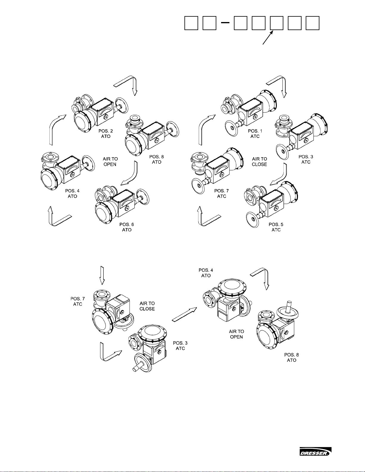
Before proceeding determine valve action (air to open/
air to close), refer to the appropriate figure (Figure 10 to
open, Figure 11 to close). To obtain proper alignment,
the lever must be oriented on the shaft so that the slot
in the end of the shaft and arrows or indicator lines are
aligned as shown; with the ball in the closed position,
the distance between the top of the bracket and the
top of the pivot pin must be as shown.
F. Flip lever (32) and lever arm (64) and replace on
shaft 90 away from original position. Replace
indicator arm (35). Slide bracket back onto bracket
mounting studs (26), replace washers (18) and nuts
(24) and tighten. Slide packing flange (23) back
over packing flange studs (25) and replace packing
flange stud nuts (24) and tighten.
G. Replace actuator on bracket in correct mounting
position for air action. Replace actuator stud nuts
(75) and washers (76). Position lever (32) and lever
arm (64) so that rod end bearing (94) lines up in lever
(32). Tighten lever cap screw (33).
H. Place ball plug (2) in closed position. If actuator
action is air to open, loosen rod end bearing nut (93)
and adjust position of rod end bearing (94) so that
holes in lever (32) and rod end bearing (94) line up.
Insert pivot pin (39) and replace retaining rings (40).
I. If action is air to close, place ball plug (2) in closed
position and pneumatically stroke actuator fully.
Do not exceed maximum air supply pressure.
J. For both air to open and air to close action, stroke valve
fully to ensure proper closure of ball plug and operation
of valve. Tighten rod end bearing locknut (93).
When stroking valve keep hands and equipment
clear of ball plug and seal ring to avoid injury or
damage to personnel or equipment.
K. Replace handwheel bracket (62), cap screws (70)
and lockwashers (71) on opposite side of actuator
bracket from where originally found. Insert handwheel
assembly in bracket and replace clevis pin (66),
retaining rings (63), lever arm bearing (65) and pivot
pins (72). Replace shaft cover (42) and screw (43).