Dresser Masoneilan Camflex II 35002 Series User manual

Masoneilan®
Series 35002
Camflex II Valve Instructions
Includes rolling diaphragm, and manual actuator
Instruction N°
EF 5000 E
01/2004

Instruction No EF 5000 E
01/2004
2
1. - INTRODUCTION ........................................... 3
2. - GENERAL ..................................................... 3
3. - PRINCIPLE OF OPERATION ....................... 4
4. - UNPACKING ................................................. 5
5. - INSTALLATION............................................. 5
6. - AIR SUPPLY PIPING .................................... 5
7. - PLACING IN SERVICE ................................. 5
8. - DISASSEMBLY............................................. 6
8.1 - ACTUATOR REMOVAL FROM BODY S/A...........6
8.2 - ACTUATOR COMPLETE DISASSEMBLY............7
8.3 - VALVE BODY.........................................................7
9. - MAINTENANCE ............................................ 9
9.1 - SPRING DIAPHRAGM REPLACEMENT...............9
9.2 - BODY S/A INTERNAL PARTS ............................10
9.3 - YOKE ASSEMBLY...............................................11
10. - REASSEMBLY PROCEDURES.................. 11
10.1 - SPRING DIAPHRAGM ACTUATOR....................11
10.2 - SPRING DIAPHRAGM ACTUATOR ON
BODY S/A.............................................................11
10.3 - HANDWHEEL REASSEMBLY.............................12
10.4 - LIMIT STOP REASSEMBLY................................12
10.5 - VALVE BODY REASSEMBLY.............................12
10.6 - SEAT RING ALIGNMENT....................................13
10.7 - DVD PLATE REASSEMBLY................................14
11. - ACTUATOR STEM ADJUSTMENT ............ 14
12. - CHANGING BODY POSITION.................... 16
13. - CHANGING ACTUATOR ACTION ............. 16
14. - MANUAL ACTUATOR OPTION ................. 17
14.1 - DISASSEMBLY PROCEDURE............................17
14.2 - MAINTENANCE ...................................................17
14.3 - REASSEMBLY PROCEDURE.............................17
Summary

Instruction No EF 5000 E
01/2004
3
The following instructions are designed to assist
maintenance personnel in performing most of the
maintenance required on the Camflex® II valve and
if followed carefully will reduce maintenance time.
Masoneilan has highly skilled Service Engineers
available for start-up, maintenance and repair of our
valves and component parts. In addition, regularly
scheduled training programs are conducted to train
customer service and instrumentation personnel in
the operation, maintenance and application of our
control valves and instruments. Arrangements for
these services can be made through your
Masoneilan Representative or District Office. When
performing maintenance use only Masoneilan
replacement parts. Parts are obtainable through
your local Masoneilan Representative or District
Office. When ordering parts always include Model
and Serial Number of the unit being repaired.
These installation and maintenance instructions
apply to 1" through 12" sizes, all available ANSI
ratings, and pneumatic actuators. The model
number, size and rating of the valve are shown on
the serial plate. Refer to figure 1 to identify the valve
mode.
1. Introduction
2. General
35002 Series Body Numbering System
Actuator Assembly digits Body Assembly Digits
SB
1st 2nd 1st 2nd 3rd 4th 5th
3 5 2
Actuator Type Body
Series Actuator Mounting Seat
Design Design
Series Design
20 Manual Actuator
35 Spring-opposed
rolling-diaphragm 35 valve
1. Parallel to pipe line,
valve closes on stem
extension
2. Parallel to pipe line,
valve opens on stem
extension
3. Perpendicular to pipe line,
valve closes on stem
extension
4. Perpendicular to pipe line,
valve opens on stem
extension
5. Parallel to pipe line,
valve closes on stem
extension
6. Parallel to pipe line,
valve opens on stem
extension
7. Perpendicular to pipe line,
valve closes on stem
extension
8. Perpendicular to pipe line,
valve opens on stem
extension
1. Metal seat
2. Soft seat
3. Metal seat
Lo-dB
4. Soft seat
Lo-dB
5. Ceramic
TRIM
2SB(1)
(1) optional, Camflex with separable bonnet. Figure 1

Instruction No EF 5000 E
01/2004
4
The concept of the Camflex® II valve is based on an
eccentrically rotating spherical plug contained in a
free flow design ANSI Class 600 body. The plug
seating surface is joined by flexible arms to a hub
which slides onto a rotating shaft. The plug is free to
center itself along the axis of the shaft. A positive
seal between plug and seat is achieved by elastic
deformation of the plug arms. The chamfered seat
ring is fixed in the valve body by a threaded retainer.
The plug and shaft are rotated through an angle of
50° by a lever linked to a powerful spring-opposed
rolling diaphragm actuator.
The solid disk-type handwheel and locking lever,
provided as standard features on the Camflex® II
valve and are mounted on the yoke opposite the
actuator. The handwheel may be used as a manual
actuator or as a limit stop. A threaded hole in the
opposite side of the yoke accommodates a cap
screw and locknut which may be inserted as a limit
stop in the other direction, or in combination with the
handwheel to lock the valve in a selected position.
The handwheel on Camflex® II is designed to be
used for emergency action only.
The actuator is generally mounted with air-loading to
counter the dynamic torque on the plug. In figure 2
the flow direction tends to open the plug and the
actuator is oriented to close it with increasing air
pressure. The actuator spring force assists plug off-
balance forces to open the valve on air failure. If the
valve is to close on air failure, the body would be
turned around in the line so that flow tends to close
theplugandtheactuatorpositionwouldbereversed.
The Camflex® II valve has a modified linear flow
characteristic, which is the same in either flow
direction. It can be easily transformed to an equal
percentage when equipping the valve with a
positioner 4700 series, 8000 series, SVI (Smart
Valve Interface) or FVP.Reduced TRIM factors 0.4
and 0.6 are available on all sizes. The flow capacity
of a 0.4 factor is 40% of the nominal capacity of the
valve and it is 60% for the 0.6 factor. Factors 0.1 and
0.2 are available on the DN 25 (1") valve.
The ability of the Camflex® II valve to handle a wide
range of process fluid temperatures is due to the
long integrally cast bonnet. This affords ample
radiation surface to normalise the packing
temperature. Therefore, with self-lubricating TFE
Aramid fiber packing, the valve handles
temperatures from - 200°C to + 400°C (-320°F to
+750°F). When insulating the valve, do not insulate
the body neck (see figure 3).
3. Principle of operation
Seat Ring
Fluid flow
Plug
Guide Bushing
Flexible arms
Guide Bushing
Shaft
Air
Actuator
Lever
Handwheel
Figure 2
Figure 3

Instruction No EF 5000 E
01/2004
5
Care must be exercised when unpacking the valve to
prevent damage to the accessories and component
parts. Should any problems arise, contact the
Masoneilan Representative or District Office.
Note: For ease of shipment and to prevent damage,
valves equipped with the spring diaphragm actuator
are shipped with the handwheel unassembled. Refer
to section 10.3 for handwheel assembly procedures.
The Camflex® II valve has been assembled at the
factory in accordance with specify instructions
concerning flow direction and actuator mode. The
valve must be installed so that the controlled
substance will flow through the valve in the direction
indicated by the flow arrow (25), which is located on
the upper part of the valve body neck. The valve
actuator should be installed so the actuator is above
the centerline of the shaft. To install the valve in the
line, proceed as follows:
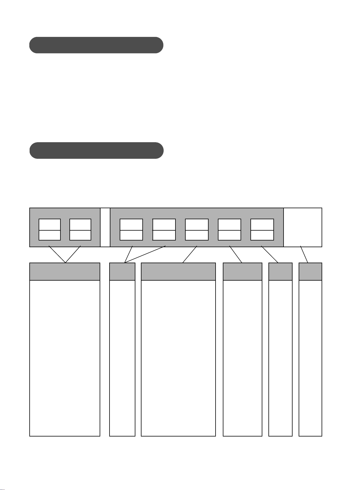
A. Check the model number on the serial plate (56)
against the numbering System described in
figure 1 to determine the valve mode.
B. Clean piping and valve of ail foreign material
such as welding chips, scale, oil, grease or dirt.
Gasket surfaces should be thoroughly cleaned to
insure leak proof connections.
C. To allow for in-line inspection, maintenance or
removal of the valve without service interruption,
provide a manually operated stop valve on each
side of the Camflex® II valve with a manually
operated throttling valve mounted in the by-pass
line.
Note: If a flanged Camflex® II is being installed
and the distance between flanges is established
by ANSI or DIN, spool pieces (spacers) are
inserted between the line flange and the valve
body flange. Gaskets and valve bolting are then
installed and torqued using standard flange and
line bolting criteria.
D. For flangeless valves, refer to figure 23 and
determine the correct size and quantity of bolts
to be used for the valve and flange rating.
E. If the valve is to be installed in a horizontal
position, install the lower flange bolting to
provide a cradle, which will help support, the
valve while installing the remaining bolts.
F. Place the valve in the line.
G. Select and install correct gaskets.
Note: Spiral wound gaskets, suitable for service
conditions are recommended.
H. Insert remaining flange bolting insuring that the
bolts align with the special bosses on the body,
which assure the valveis centered in the line and
also prevent rotation.
Note: For certain flange standards, through
bolting is not possible because of the valve body
neck or bonnet. To accommodate flange bolting,
guide arms with threaded holes or slots are
provided on the valve body to receive flange
bolts (refer to figure 22).
I. Tighten flange bolts evenly and firmly.
Note: If the valve is equipped with manual
handwheel, it may now be placed in service.
Air is supplied to the actuator through the 1/4" NPT
tapped connection in the diaphragm case. Refer to
figure 14 to determine the correct supply pressure
and tubing size, then connect air supply piping.
Note: When the valve is equipped with regulators or
other accessories supplied by Masoneilan, only
connections to those accessories are required since
the piping to the actuator is connected at the factory.
Some valves equipped with electrical accessories
will require appropriate wiring. Refer to
manufacturer's instructions for correct wiring
information.
With the valve properly installed in the line and all air
or electrical service connected, it is recommended
Caution: Any change in flow direction or
actuator mode must be accomplished as
outlined. In this instruction otherwise
equipment malfunction could result.
4. Unpacking
5. Installation
Cantion: If the valve is to be insulated, do not
insulate the valve body neck.
Caution: Do not exceed maximum air
pressure indicated. Personal injury and
equipment malfunction could result.
6. Air Supply Piping
7. Placing in Service

Instruction No EF 5000 E
01/2004
6
that the valve be run through one cycle to insure
proper functioning. Proceed as follows:
A. Back off the handwheel (53) so that it will not
interfere with the operation of the valve and
tighten the handwheel lock (52).
Note: If the valve is equipped with the optional
limit stop (77), it should also be backed off to
prevent interference with the operation of the
valve.
B. Apply correct air pressure to the actuator.
Note: Valve should function smoothly and with
maximum pressure, the valve indicator (6)
should show full open or full close depending on
valve mode.
C. Relieve air pressure and return valve to normal
mode.
D. Gradually open process lines to place the valve
in service.
E. Check for leaks. Repair as required.
F. If desired, the handwheel may be used as a limit
stop. Set in desired position and lock.
G. If the optional limit stop (77) is used, set and
tighten locknut.
8.1 ACTUATOR REMOVAL FROM
BODY S/A
(Refer to figure 16 and figure 17)
Maintenance required on the internal components of
the valve or re-orientation of the actuator and body,
requires that the actuator and yoke be removed from
the valve. On the 6", 7" and No 9 actuators, for ease
of handling and reassembly, it is recommended that
the spring barrel be removed from the yoke and then
the yoke separated from the valve body.
Note: If the valve will be reassembled in the same
orientation, it is recommended that the body to yoke
orientation and the actuator to yoke orientation be
marked in relation to each other. This will simplify
reassembly.
A. If required, remove the valve from the line.
B. Remove rear cover (29) and front cover (32) by
removing the two cover screws (30).
C. Remove bottom cover (11) and spring barrel
boss cover (58).
D. Remove indicator (88) by removing the two
screws (89).
E. Loosen handwheel lock (52) and turn handwheel
(53) so it does not interfere with the movement of
the lever (34).
Note: On valves supplied with the optional limit
stop, (figure 17) loosen nut (78) and back off the
limit stop screw (77) so it will not interfere with
the movement of the lever (34).
F. Connect an air line to the actuator supply port
and using a manual loading panel or regulated
air supply, apply enough air pressure to the
actuator so the lever will move to an intermediate
position.
Note: If the valve is to be reassembled using the
same orientation, it is recommended that the
yoke (33) and lever (34) alignment, in the closed
position, be marked to simplify reassembly and
alignment of the lever and shaft to insure proper
valve functioning. See figure 17.
G. Remove clevis pin clips (5).
H. Remove clevis pin (7).
I. Relieve air pressure from actuator enabling
clevis (35) to disengage from lever (34).
Note: If the valve is equipped with a positioner,
refer to the appropriate positioner instruction for
procedures on cam or lever removal. Then
proceed to step K.
J. Remove shaft cover (9) by removing cover
screw (10).
K. Insure spring barrel is properly supported.
Caution: Always insure process pressure, a
pressure and electrical service are off and the
valve is isolated and relieved of pressure
before performing maintenance on the valve.
Caution: Prior to performing maintenance on
the valve, isolate the valve, vent the process
pressure and shut off supply and signal air
lines to the actuator.
8. Disassembly
Caution: Do not exceed pressure listed in
figure 14 for actuator used. Do not use
handwheel to move the lever.
Caution: Depending on the size and weight of
the actuator. It is recommended that proper
lift and support procedures be utilised when
removing the spring barrel or yoke.

Instruction No EF 5000 E
01/2004
7
L. Loosen and remove cap screws (36) and
lockwashers (37), then remove spring
barrel (38).
M. Loosen lever capscrew (49).
N. Loosen the stud nuts (94) and disengage the
packing flange.
O. Loose the stud nuts (27) to separate the actuator
from the body S/A.
Note: With body secure, grasp lever and yoke and
separate. Yoke, lever and packing flange are
removed at the same time. The yoke may have to be
struck with a soft face mallet to break it loose.
8.2 ACTUATOR COMPLETE
DISASSEMBLY
The spring diaphragm actuator used on the
Camflex® II valve was designed basically as a low
cost non-replaceable item and therefore
disassembly is not recommended. However, in
some instances and for emergency purposes,
disassembly may be required. Proceed as follows.
A. If the actuator is not removed from the body
proceed to the paragraph 9.1 A. to 9.1 L.
B. Loosen locknut (46) then remove the clevis (35)
and the locknut (46).
C. Loosen and remove capscrew (41) and remove
diaphragm case (42) and diaphragm (40).
D. Using a deep socket, loosen and remove locknut
(45) and washer (44).
E. Remove piston (43) and spring (39) and inspect
all components.
F. Proceed to section 10.2 for reassembly.
8.3 VALVE BODY (Refer to fig. 4 & 16)
Maintenance to the internal components required on
the Camflex® II Valve can normally be easily
determined since the seat ring and plug can be seen
once the valve is removed from the line. Although it
may be determined that the seat ring does not need
replacement, it must be noted that the new plug and
seat ring must be lapped thus requiring the
disassembly of the body. It is recommended that
both seat ring and plug be replaced if one or the
other is damaged due to service.
After the actuator has been removed from the body,
disassemble the valve using the following
procedure:
A. In case of 35000 SB (Separable Bonnet) before
continuing in D it is necessary to loose and
remove the nut 104 to separate the bonnet with
the packing and the packing follower (15) from
the body.
B. Remove packing follower (15).
C. Remove safety pin (16).
D. Pull on the shaft (19) to remove it.
Note: Difficulty is sometimes encountered when
removing the shaft from the plug mainly due to
an excessive accumulation of deposits between
the plug splines and theshaft. Application of heat
to the plug shaft bore while using one of the
following methods will facilitate removal.
If the shaft is not removed easily, replace the
lever (34) on the splined end of the shaft (19), tighten
the lever capscrew (49) and using a mallet, tap the
lever (34) as close to the shaft as possible and
remove the shaft (19).
Note: If the shaft cannot be removed by tapping the
tightened lever, figure 20 illustrates an alternative
method of removal. Using a pipe nipple of suitable
size and length and reversing the packing flange and
stud nuts as shown, the shaft may be jacked out of
the body. For larger valves the use of an additional
washer and nipple to assist in holding the tightened
Lever is recommended. The lever should be
tightened at a point where the hub on the lever is
flush with the end of the spline.
E. The components which should come out with the
shaft (19) are: the packing (17), packing box ring
(23 or 100), spacer tube (20) and upper guide
bushing (21).
Caution: Prior to performing maintenance on
the valve, isolate the valve, vent the process
pressure.
Caution: The purpose of the safety pin is to
prevent the shaft from being pushed out if the
yoke is removed while the valve is still
pressurised. The internal components of the
valve cannot be removed without first
removing the safety pin.
Caution: When using heating devices. Insure
that proper safety practices are observed.
Such items as the flammability and toxicity of
the controlled substance must be considered
and proper precautions taken.

Instruction No EF 5000 E
01/2004
8
Note: The spacer tube (20) and upper guide
bushing (21) may remain in the body. They
should be removed. The spacer tube (20) can
only be removed by pulling it out the bonnet end
of the body. The upper guide bushing (21) may
be pushed through the body after removing the
plug or pulled through the bonnet end of the
body. On valves designed for use on slurry or
viscous service, the upper guide bushing has an
inner "O" ring (92) and an outer "O" ring (93) and
the lower guide bushing has inner "O" ring (95)
and outer "O" ring (96) (Refer to figure 4).
F. Remove the plug (4) through the end of the body
opposite the seat ring.
G. Remove the lower guide bushing (22).
Note: A groove is provided in the bushing for
prying out the bushing using a screwdriver. If the
bushing will be pried out it should be pried from
two sides to prevent jamming the bushing during
removal. If the bushing does not come out easily,
fill the bushing with grease, insert the shaft (19)
into the valve insuring that the machined portion
of the shaft starts into the lower guide bushing.
Using a soft faced mallet, strike the end of the
shaft lightly until the bushing is pushed out
partially. Remove the shaft and complete
removal of the bushing by prying out using the
groove provided.
8.3.1 Seat Ring Removal (Refer to figure 16)
The following procedures outline the recommended
method for removing the seat ring retainer (3) with
the use of retainer wrenches. Masoneilan
manufactures and has available, for a nominal price,
seat ring retainer wrenches for the Camflex® II, 1"
through 4" sizes. lt is highly recommended that
wrenches be purchased or fabricated to facilitate
removal and reassembly of the seat ring (2) since
SPECIFIC TORQUES MUST BE ACHIEVED to
obtain tight shutoff and insure proper functioning of
the valve.
Figure 5 shows the recommended materials,
thickness and method of construction along with
specific dimensions to facilitate construction.
A. Secure the valve body in a vise or appropriate
holding device with the seat ring facing up.
B. Place retainer wrench so it engages retainer
lugs.
C. Engage the retainer wrench with an impact
wrench or suitable wrench and loosen, then
remove retainer (3) by turning counter-
clockwise.
D. Lift out seat ring.
Note: In an emergency, drifts may be used to
remove the seat ring retainer. However, two
drifts should be used and placed in the slots 180°
apart and struck simultaneously.
8.3.2 DVD Removal (Refer to figure 16)
In case of Camflex® with the DVD option, model
number 35x3x or 35x4x, the DVD is installed in the
body, it is recommended to use the DVD wrenches to
remove this device (105). Masoneilan manufactures
and has available, for a nominal price, DVD wrenches
for the Camflex® II, 1" through 12" sizes. lt is highly
recommended that wrenches be purchased or
fabricated to facilitate removal and reassembly of the
DVD (105) since SPECIFIC TORQUES MUST BE
ACHIEVED to insure proper clamping of this DVD
plate.
Caution: Do not pry the bushing using the
seat for leverage. If the bushing cannot be
easily removed, proceed to section 8.3.1 and
remove the seat ring retainer and seat ring
then remove the bushing. Place a piece of
soft stock (brass, etc.) between the inner seat
shoulder and prying device to prevent
damage to the seat sealing area of the body.
92
93 21 22 96
95
Figure 4 - Optional “O” ring arrangement
Care must be taken to avoid damage to the
gasket face on the valve body.
A
A
B
WELDED
KEY
STOCK
3/16" STEEL PLATE
A = O.D. Seat Ring Retainer
B = Width of slot in Retainer
C = I.D. of Seat Ring Retainer
WELDED
HEX NUT C
Figure 5

Instruction No EF 5000 E
01/2004
9
Figure 6 shows the recommended thickness and
method of construction along with specific
dimensions to facilitate construction.
A. Secure the valve body in a vise or appropriate
holding device with the plug side facing up (refer
to figure 16).
B. Place DVD plate wrench so it engages retainer
lugs.
C. Engage the retainer wrench with an impact
wrench or suitable wrench and loosen, then
remove DVD (105) by turning counter-clockwise.
9.1 SPRING DIAPHRAGM
REPLACEMENT
(Refer to figures 16 and 17)
The recommended maintenance to be performed on
the Camflex® II Spring Diaphragm Actuator is limited
to the replacement of the diaphragm (40). Removal
of the actuator from the valve is not required. To
replace the diaphragm, proceed as follows:
Handwheel (53) and limit stop (77) must be backed
off to allow free travel of the lever (34).
A. Bypass the valve, shut off stop valves and isolate
valve in compliance with CAUTION note listed
above.
B. Shut off and disconnect air supply tubing to the
actuator.
C. Remove the four capscrews (41) from
diaphragm case (42) and remove diaphragm
case.
D. Remove diaphragm (40).
Note: Diaphragm is glued to the top of the
piston (43).
E. Removed tape or glue from the top of the piston
and clean thoroughly
F. Clean diaphragm case (42) and spring barrel
(38) at the area that engages the diaphragm
bead in preparation for reassembly.
Note: To hold the diaphragm in place on the
piston, an adhesive disc (adhesive both sides) or
rubber cement is used. If rubber cement is used,
it should be applied to both the piston and the
diaphragm or in accordance with the
manufacturer's directions for the adhesive used.
For recommended adhesives see figure 15.
G. Apply adhesive tape or cement to the top of the
piston.
H. The inscription "Piston Side" is located on the
diaphragm (40). if used, apply cement to this
side of the diaphragm.
I. Center and adhere diaphragm (40) to the top of
the piston (43) (see figure 7, step A).
A
mm
(in)
d
mm
(in)
D
mm
(in)
H
mm
(in)
T
mm
(in)
DN 25
(1”) 27
(1.063) 3.6
(0.142) 2
(0.079) 2
(0.079) 10
(0.4)
DN 40
(1”½)38
(1.496) 4
(0.157) 3
(0.118) 3
(0.118) 12
(0.4)
DN 50
(2”) 49
(1.929) 4
(0.157) 3
(0.118) 3
(0.118) 18
(0.7)
DN 80
(3”) 74
(2.913) 4.5
(0.177) 4
(0.157) 4
(0.157) 20
(0.8)
DN 100
(4”) 98
(3.858) 5
(0.197) 7
(0.275) 7
(0.275) 20
(0.8)
DN 150
(6”) 150
(5.905) 6
(0.236) 9
(0.354) 9
(0.354) 25
(1.0)
DN 200
(8”) 201
(7.913) 6
(0.236) 10
(0.394) 10
(0.394) 25
(1.0)
DN 250
(10”) 250
(9.843) 6
(0.236) 10
(0.394) 10
(0.394) 30
(1.2)
DN 300
(12”) 298
(11.732) 7
(0.276) 12
(0.472) 12
(0.472) 30
(1.2)
Figure 6
Caution: Care must be taken to avoid damage
to the gasket face on the valve body.
A
H
T
d
D Caution: The valve must be isolated and free
from any service pressure. All electrical or air
pressure to component parts must be off.
Pressure to the actuator must be relieved.
9. Maintenance

Instruction No EF 5000 E
01/2004
10
J. Roll the diaphragm (40) inside the spring barrel
(38) until the bead on thediaphragm is located in
the spring barrel groove (see figure 7, step B).
K. Place the diaphragm case (42).
L. Insure that the diaphragm case (42) is evenly
seated on the spring barrel (38), insert the four
capscrews (41) and tighten evenly.
M. Connect air supply line to diaphragm case (42).
N. Turn on air supply and check for leaks.
O. If necessary reposition handwheel (53) and limit
stop (77), (optional) to desired location and place
valve back in service.
9.2 BODY S/A INTERNAL PARTS
During a maintenance of Camflex® II valve it is
necessary to inspect all the internal parts to
determine if they are worm, corroded and damaged,
especially the following seating area:
-body and seat ring contact area.
-the sealing surface of the plug and seat ring.
-the guide surface of the shaft and the guide
bushing.
All parts which are damaged must be replaced by
original Masoneilan spare parts.
9.2.1 Hard Seat Lapping
Lapping is the process of working the valve sealing
parts against each other, with an abrasive, to
produce a close fit. To perform the lapping operation,
proceed as follows.
A. Clean the seat ring sealing surface in the valve
body and the seat ring shoulder.
B. Apply a small amount of fine grinding compound
to the seat ring shoulder.
C. Insert the seat ring into the body and lap lightly
by rotating the seat ring in the body insuring that
the entire seat ring sealing surface in the valve
body is lapped. Do not rotate in one place.
Note: Figure 8 illustrates a simple tool which
may be fabricated to facilitate this lapping
operation on smaller valves.
D. Remove seat ring and clean thoroughly.
Caution: Insure that the capscrew holes in the
diaphragm case and spring barrel are aligned
to prevent twisting of the diaphragm in
aligning the holes. The diaphragm case (42) is
normally assembled with the air inlet port
placed on the bottom side of the actuator.
Depending on the desired location, It can be
placed in any desired position around the
spring barrel which allows the capscrew
holes to line up. However, the drain hole in
the spring barrel must always be facing down
to allow for draining of any moisture which
may enter the spring barrel cylinder (38). If
the valve is equipped with the optional purge
line that line is inserted into the drain hole.
STEP A STEP B STEP C
Outer Face Glue Limit
Figure 7
FABRICATED
HANDLE
TYPICAL LAB
BOTTLE STOPPER
Figure 8

Instruction No EF 5000 E
01/2004
11
E. Place seat ring on a flat surface with the seating
area facing up.
F. Apply a small amount of fine grinding compound
to the seat ring seating surface.
G. Lap the plug lightly against the seat ring while
turning and oscillating the plug in all directions.
H. Clean seat ring, plug and valve body thoroughly
in preparation for reassembly.
9.2.2 Soft Seat
Do not lap the soft seat ring to the plug ; however, the
seat ring must be lapped to the valve body. The
procedure for lapping the seat ring to the body is the
same as stated in items A. through D of section 9.2.1
on Hard Seats.
9.3 YOKE ASSEMBLY (Refer to figures
16 and 17)
Maintenance required on the yoke (33) is limited to
replacement of the grommet (12) and the shaft
bearing (8). To replace either, the actuator must be
separated from the body. (Depending on the type of
actuator used, refer to appropriate section). Insert
the grommet into the yoke with the recessed part of
the grommet towards the shaft bearing. The shaft
bearing (8) is slip fit into the yoke and is removed by
pushing it out towards the grommet.
10.1 SPRING DIAPHRAGM ACTUATOR
When the actuator has been disassembled using
section 8.2 to reassemble the actuator, proceed as
follows:
A. Replace spring (39) in piston (43).
B. B. Replace washer (44) and locknut (45).
Note: Locknut (45) must be threaded the full
length of the threads.
C. To reassemble the diaphragm and upper
diaphragm case, refer to section 9.1, steps E.
through L.
D. Replace locknut (46) and clevis (35).
E. Determine correct orientation and replace
actuator on yoke and replace lockwashers (37),
capscrews (36) and tighten firmly.
F. Refer to section 11. for actuator stem
adjustment.
10.2 SPRING DIAPHRAGM ACTUATOR
ON BODY S/A
(Refer to figures 16 and 17)
After completing the required maintenance or
changing valve, actuator and yoke assembly,
reassemble using the following procedure:
A. Determine correct valve to actuator orientation.
B. If required, reposition body studs (28) and
packing flange studs (13).
Note:
Depending on the actuator position, insure
that the body studs (short studs) when placed
through the yoke holes will be positioned in the
front of the yoke opening for ease of accessibility.
C. Insure that grommet (12) and shaft bearing (8)
are in the yoke. Turn shaft so the plug is in the
closed position.
D. Slide the valve shaft partly into the lower yoke
opening, allowing enough room to place packing
flange (14) over the shaft (19).
Note: Packing flange (14) is placed on the shaft
(19) with the concave side toward the valve
packing (17).
E. Insure slots in packing flange (14) line up with
packing flange studs (13).
F. With packing flange on the shaft, continue sliding
the valve shaft toward the yoke (33) and through
the grommet (12) in the yoke (33).
G. Place the lever (34) in the yoke and in line with
the shaft so the boss on one side of the lever
shaft hole is toward the shaft bearing (8) and
engage the shaft to the lever splines.
Note:
Shaft must engage lever so the indicator dot
on the clevis pin, when placed in the lever hole,
shows the valve closed. Temporarily place clevis
pin into lever (34) and check indicator dot alignment.
Dot should just start touching the closed indicator
line on the front cover (32) (Refer to figure 18). If the
orientation is not changed, align lever and mark on
yoke then check alignment. (Refer to figure 17).
H. Slide shaft completely through lever to engage
shaft bearing (8). Yoke should now be fully
seated on the valve bonnet flange.
Caution: Insure the bearing seat in the yoke is
clean. The bearing should slide in
easily. Do not use excessive force to push
bearing in.
10. Reassembly Procedures
Caution: Do not use air pressure to check
alignment, since during normal operation and
with full air pressure, the Indicator may
overshoot the closed Indicator mark on the
cover. This is acceptable.

Instruction No EF 5000 E
01/2004
12
I. Replace and tighten body stud nuts (27).
J. Replace packing flange stud nuts (94) and finger
tighten only.
K. Slide the lever (34) on the shaft (19) toward the
valve and tighten lever capscrew (49).
L. Pull the lever and shaft toward the bearing (8) in
the yoke.
M. Loosen lever capscrew (49) and slide lever (34)
so it will shoulder against the shaft bearing (8)
and tighten capscrew (49).
Note: if the actuator cylinder (38) has been
removed proceed to step N. If it has not, proceed
to section 11. on actuator stem adjustment.
N. Determine the desired actuator action and
replace actuator cylinder (38) on the yoke (33)
and secure in place with four capscrews (36) and
lockwashers (37).
O. Proceed to section 11. on actuator stem
adjustment.
10.3 HANDWHEEL REASSEMBLY
A. Place the valve so the position cover (11) is up.
B. Remove Truac ring (50) and handwheel washer
(51) from the handwheel powerscrew.
C. Insert handwheel powerscrew with lock (52) in
place into the appropriate hole in the yoke and
screw in clockwise.
D. Replace the washer (51) and Truac ring (50)
E. Back off handwheel lightly against washer and
lock in the off position with lock (52).
F. Replace bottom cover (11) by snapping in place.
Note: To use the handwheel, loosen the lock (52)
and turn. The handwheel can be use as a limit stop
on the valve by locking it in any position.
10.4 LIMIT STOP REASSEMBLY
Two different types of assembly for the limit stop in
function of the actuator size: see figure 9.
10.5 VALVE BODY REASSEMBLY
(Refer to figure 16)
Prior to reassembly, the valve body should be
thoroughly cleaned and the seat ring and plug may
be lapped as indicated in section 9.2. Upon
completion of the above, proceed as follows:
A. Apply a small amount of thread lubricant to the
seat ring retainer threads and install seat ring
retainer (3) and hand tighten only.
B. Place valve body (1) on flat surface so that the
seat is down.
C. Coat lower guide bushing (22) with
recommended lubricant and insert into the body.
Note: Groove in the guide bushing (22) must be
towards the body center.
Refer to figure 10 for correct assembly
sequence. If the shaft (19) is the older design it
may have a circular grove, if so install the
retaining ring.
Caution: This is required to insure the shaft
(19) is shouldered on the shaft bearing (8) and
to insure free operation of the valve.
LIMIT STOP STD
CAMFLEX 6" and 7"
LIMIT STOP STD
CAMFLEX 4.5"
Figure 9
Lubricants and sealers are required during
reassembly. Figure 15 identifies
recommended products for certain service
conditions. Insure that any lubricant used is
compatible with service conditions.
Caution: Do not tighten the seat ring retainer
to torque specification at this time.
232021422
19
19
Figure 10

Instruction No EF 5000 E
01/2004
13
D. Coat the upper guide bushing (21) spacer tube
(20) and the shaft splines (plug side) with
recommended lubricant.
E. Insert the spacer tube (20) over the lubricated
part of the shaft.
F. Place upper guide bushing (21) on the shaft (19).
G. Place plug (4) in body so it rests on the seat.
H. Insert the shaft sub-assembly into the body (1)
and engage plug (4) and lower guide
bushing (22).
Note: The shaft (19) should be inserted into the
plug so that when the plug is seated, the slot at
the outer end of the shaft is perpendicular to the
flow through the valve.
In case of 35000 SB, separable bonnet version,
follow the operations described from O to W.
I. Install the packing box ring (23), bevel side out,
over the shaft (19) and into the valve bonnet
being sure that the hole in the ring is aligned with
the threaded port in the bonnet.
J. Apply a suitable lubricant to the threads of the
safety pin (16) and screw into the body neck and
tighten.
K. Install packing (17) insuring that the skive cut of
each piece of packing is offset approximately
120° from that of the adjacent piece of packing.
Note: Sizes 1" thru 3" use 7 pieces of packing;
sizes 4" thru 12" use 6 pieces of packing.
L. Install packing follower (15) rounded, bevel side
out.
M. Proceed to section 10.6 on seat ring alignment.
For O to W for separable bonnet design only:
N. If necessary, install the studs (103) in the
bonnet (102).
O. Install the stop ring (100).
P.
Place the gasket (101) in the groove of the bonnet.
The old gasket (101) must not be re-used.
Q. Place the bonnet with the studs on the body and
screw the nuts (104).
R. Tight the nuts (104) according the table figure 11.
Note: It is important to tighten the nuts step by
step, during the tightening the bonnet flange
must keep the shaft axis aligned.
S. Install packing (17) insuring that the skive cut of
each piece of packing is offset approximately
120° from that of the adjacent piece of packing.
Note: Sizes 1" through 3" use 7 pieces of
packing; sizes 4" through 12" use 6 pieces of
packing.
T. Install packing follower (15) rounded, bevel side
out.
U. Proceed to section 10.6 on seat ring alignment.
10.6 SEAT RING ALIGNMENT
Aligning the seat ring (2) and plug (4) is required
whenever the seat ring or plug have been replaced
or disassembled. Proceed as follows:
A. Place valve on flat surface with retainer (3) and
seat ring (2) facing up.
Note: The casting marks (=) indicate the seat
ring end of the body.
B. Remove the retainer ring (3) and the seat
ring (2).
C. Apply a thin coat of sealant to the seat ring
shoulder that engages the body and replace seat
ring (2).
D. Apply a small amount of thread lubricant to the
seat ring retainer threads and install seat ring
retainer (3) and hand tighten only.
E. Replace lever (34) on valve shaft (19) and
tighten lever capscrew (49).
F. Using the lever (34) manually close the plug with
sufficient force to allow seat ring and plug to
align.
When a recessed groove exits in the spacer
tube (20), this spacer tube (20) must be placed
on the shaft (19) so that the shaft shoulder or
retaining ring fits into the recessed groove on
one end of the spacer tube (20).
Caution: the pin is safety part which cannot
be replaced by a plug, use only Masoneilan
supplied safety pins.
Pin must engage hole in packing box ring
(23). Test by manually pulling on the shaft to
verify engagement.
Torque m.N Torque lb.ft
DN 25 (1")
DN 40 (1" ½)
DN 50 (2") 30 22
DN 80 (3") 75 55
DN 100 (4") 75 55
DN 150 (6") 145 107
Figure 11
Caution: Do not tighten the seat ring retainer
to torque specification at this time.

Instruction No EF 5000 E
01/2004
14
G. Using the seat ring wrench, tighten seat ring
retainer to the minimum torque value specified in
figure 12.
Note: In some cases, for the valves from 3" to 12"
with metal seat, the alignment can be improved by
placing a piece of paper 0.10mm (0.004") thick and
approximately 6 mm (1/4") wide at a point where the
leading edge of the plug contacts the seat ring and
close the plug. With a slight pressure on the lever,
the paper strips should both beclamped in place. For
the valve 8" to 12", the piece of paper shall be 0.20
mm (0.008") thick and 12 mm (1/4") wide.
H. Proceed to section on body to actuator
assembly.
10.7 DVD PLATE REASSEMBLY
Using the same method and tooling as described in
8.3.2 tighten the Lo-dB plate at the indicated torque
given in the table of figure 13.
(Refer to figures 16 and 17).
Correct actuator stem adjustment is imperative for
proper valve functioning. With the actuator
assembled to the valve in the desired location and
orientation proceed as follows:
Note: If any of the following steps were completed
during maintenance or reorientation of actuator to
valve, proceed to the next step.
A. Remove front cover (32) and rear cover (29) by
removing the two-cover screws (30).
B. Back off handwheel (53) so it does not interfere
with the operation of the lever (34).
C. If applicable, back off optional limit stop (77) so it
will not interfere with the operation of the
lever (34).
D. Apply air pressure to the actuator and move
lever (34) to an intermediate position.
E. Remove adjustable indicator (88) by removing
the two screws (89).
F. Remove clevis pin clip (5), remove clevis pin (7).
G. Relieve air pressure to the actuator to allow the
clevis (35) and lever (34) to separate.
Note: If the unit is air-to-open, separate clevis
(35) and lever (34) then loosen clevis locknut
(46) and remove clevis.
H. Insert clevis pin (7) back in lever (34).
I. Manually push the lever(34) so the valve is in the
closed position.
J.
Temporarily replace front cover (32) and check the
location of the clevis pin (7) in relation to the closed
Valve size Minimum torque
N.m Ft.lb
DN 25 (1") 81 60
DN 40 (1"1/2) 130 95
DN 50 (2") 135 100
DN 80 (3") 395 290
DN 100 (4") 490 363
DN 150 (6") 1120 825
DN 200 (8") 1320 975
DN 250 (10") 1830 1350
DN 300 (12") 3050 2250
Figure 12
Tightening torque
N.m Ft.lb
DN 25 (1") 74 54
DN 40 (1"1/2) 110 81
DN 50 (2") 135 100
DN 80 (3") 295 220
DN 100 (4") 490 363
DN 150 (6") 1050 780
DN 200 (8") 1320 975
DN 250 (10") 1830 1320
DN 300 (12") 3050 2250
Figure 13
Caution: The following procedures must be
adhered to in order to insure correct valve
functioning. Failure to do so could result in
valve damage and equipment malfunction.
Caution: Do not exceed pressure listed in
figure 14 for the actuator used. Do not use
handwheel (53) to move lever (34).
11. Actuator Stem Adjustment

Instruction No EF 5000 E
01/2004
15
position indicator mark on front cover (32).
Note: If the unit is air-to-open replace clevis
locknut (46) and clevis (35).
K. Proceed to one of the following sections for final
adjustment. Air-to-Open, section (K-1), Air-to-
Close section (K-2).
K-1. Air-to-Open
After completing step A through J of section 11.,
proceed as follows:
A. Scribe a line on the clevis (35) in line with the
inside of the yoke.
B. Connect a regulated air supply directly to the
actuator and gradually apply 8 psig for No. 9
actuator and 7 psig for the others.
C. The clevis should move at least 1/4".
D. With the lever and valve plug in the fully
CLOSED position, the holes in the clevis (35)
and lever (34) should be in line.
Note: if holes are in line proceed to step J. If not
in line, continue to next step.
E. Move lever (34) to full open position.
F. Gradually apply sufficient air pressure to
extend clevis locknut (46) to an accessible
position.
G. Loosen clevis locknut (46).
H. Reduce air pressure to actuator to 7 psig.
I. Screw clevis (35) in or out on actuator stem
so that the holes in the clevis (35) and lever
(34) are aligned with the lever and plug in the
fully closed position.
J. Insert clevis pin (7) so indicator dot is visible
through front cover (32) and secure with
clevis pin clips (5).
Note: On the 6" and 7" model actuators, without
the adjustable indicator (88), the clevis pin (7)
must be installed so it protrudes toward the front
cover (32). If the indicator dot is damaged, paint
may be applied to the end facing the front cover
(32) to make it more visible.
K. Gradually apply sufficient air pressure to
extend clevis locknut (46) to an accessible
position and tighten firmly.
L. Relieve air pressure.
M. If used, replace adjustable indicator (88) to
lever (34) with screws (89).
Note: If required, adjust indicator to front cover
indicator marks.
N. Replace front cover (32) and rear cover (29)
and secure in place with cover screws (30).
O. Replace spring barrel boss cover (58) and
bottom cover (11). (Snap fit.).
Note: Prior to placing the valve in service,
operate the valve actuator through one complete
cycle to insure proper functioning.
P. If desired, set handwheel (53) or optional
limit stop (77) to desired position.
K-2. Air-to-Close
After completing step A through J of section 11.
proceed as follows:
A. Manually push lever (34) to the full CLOSED
position.
B. Connect a regulated air supply to the
actuator.
C. Gradually apply the final air pressure
corresponding to the closed position. See
value on the serial plate.
D. With the lever (34) and valve plug in the
CLOSED position, the holes in the clevis (35)
and lever (34) should be in line.
Note: If holes are in line proceed to step H, if not
in line, continue to the next step.
E. Release air pressure so clevis (35) will
separate from lever (34).
F. Loosen clevis locknut (46).
G. Screw clevis (35) in or out so that when the
air pressure corresponding to the closed
position mentioned in C above is applied,
clevis holes and lever will be in line.
H. Insert clevis pin (7) so indicator dot is visible
through front cover (32) and secure with
clevis pin clips (5).
Note: On the 6" and 7" model actuators, without
the adjustable indicator (88), the clevis pin (7)
must be installed so it protrudes toward the front
cover (32). If the indicator dot is damaged, paint
may be applied to the end of the clevis pin (7)
facingthe front cover(32)to make it more visible.
Caution: the relationship must be as shown in
figure 18. If it is not, the yoke must be
separated from the body and the lever (34)
repositioned on the shaft. Refer to
appropriate section. Failure to comply could
result in the valve short stroking or over
stroking and could damage the valve.
Caution: Do not exceed pressure listed in
Figure 14 for the actuator used.
Caution: Do not exceed pressure listed in
figure 14 for the actuator used.

Instruction No EF 5000 E
01/2004
16
I. Tighten clevis locknut (46).
J. Relieve air pressure to actuator.
K. If used, replace adjustable indicator (88) to
lever (34) with screws (89).
Note: If required, adjust indicator (88) to front
cover (32) indicator marks with the valve in the
closed position.
L. Replace front cover (32) and rear cover (29)
and secure in place with cover screws (30).
M. Replace spring barrel boss cover (58) and
bottom cover (11). (Snap fit.).
Note: Prior to placing the valve in service,
operate the valve actuator through one complete
cycle to insure proper functioning.
N. If desired, set handwheel (53) or optional
limit stop (77) to desired position.
Changing service requirements or service conditions
may require a change in flow direction through the
Camflex® II valve. Figure 19 illustrates the various
positions and flow directions in which the valve may
be placed to accommodate requirements.
To change body position proceed as follows:
A. Refer to figure 19 and determine which is the
desired valve position, flow direction and which
actuator position is required.
B. Proceed to the appropriate section of this
instruction for the required disassembly and
assembly procedures.
A. Remove front cover (32) and rear cover (29) by
removing the two cover screws (30).
B. Remove spring barrel boss cover (58) (Snap fit.).
C. Remove bottom cover (11) (Snap fit.).
D. Using a manual loading panel, apply sufficient air
pressure to the actuator to move the lever (34) to
an intermediate position.
E. Remove clevis pin clips (5) and remove clevis
pin (7).
F. Position lever so it does not contact handwheel
powerscrew assembly.
G. Remove Truarc ring (50) and washer (51) from
handwheel powerscrew assembly.
H. Unscrew and remove handwheel powerscrew
assembly from yoke (33).
I. Remove handwheel thread plug (48).
Note: If the actuator is equipped with the
optional limit stop (77), in place of the handwheel
thread plug, it must be removed.
J. Insure spring barrel is properly supported.
K. Loosen and remove capscrews (36) and
lockwashers(37)thenremove spring barrel(38).
L. With the yoke assembled to the valve in the
required orientation, place spring barrel (38) on
desired yoke Location and secure with
capscrews (36) and lockwashers (37), and
tighten firmly.
M. Screw in handwheel powerscrew assembly into
the power screw hole of the yoke which is on the
opposite side of the spring diaphragm actuator.
Note: Handwheel action is always the same as
air action and opposes the spring.
N. Replace handwheel washer (51) and truarc ring
(50) and back off handwheel so the power screw
will not interfere with the operation of the lever.
O. Replace handwheel thread plug (48).
Note: If the valve is equipped with the optional
limit stop (77) instead of the thread plug, it must
Caution: Changing the body position and flow
direction could also require relocating the
actuator. Insure that the actuator location and
action are in accordance with the
recommended positions and modes
illustrated in figure 19. Illustrations are shown
looking at the body through the bonnet with
the actuator in front of the valve. The plug
shaft is always rotated in a clockwise
direction by the actuator to open the valve.
12. Changing Body Position
13. Changing Actuator Action
Caution: Do not exceed pressure listed in
figure 14 for actuator used. Do not use
handwheel to move lever.
Caution: Depending on the size and weight
off the actuator, it is recommended that
proper lift and support procedures be utilised
when removing the spring barrel or yoke.
Caution: If the orientation of the actuator to
valve requires that the yoke be rotated about
the valve, it is recommended that section 12.
on changing yoke position be accomplished
before proceeding.

Instruction No EF 5000 E
01/2004
17
now be installed, but insure it is backed off as not
to interfere with the operation of the lever at this
time.
P. Proceed to section 11. on actuator stem
adjustment.
The manual type actuator is designed to close the
valve by rotating the handwheel in a clockwise
direction. Anti-rotation of the handwheel is obtained
through a detente device located between
handwheel (53) and retainer (87).
14.1 DISASSEMBLY PROCEDURE
The disassembly procedure for manual actuator is
similar to the procedure for spring diaphragm
actuator see § 8.1.
14.2 MAINTENANCE
Routine maintenance of the manual actuator
requires that a suitable lubricant be periodically
applied to the handwheel powerscrew.
Bearings may require replacement due to service
conditions or corrosion.
The replacement of the handwheel detent
mechanism should be required.
14.3 REASSEMBLY PROCEDURE
There is no specific adjustment for the reassembly of
manual actuator. For details see figure 21.
14. Manual Actuator Option
Valve size Actuator Size
Diameter
Maximum Air Supply Recommended tubing
A 564 Gr 630 Shaft Austenitic Stainless Steel
Shaft
Inch (mm) kPa Psi kPa Psi mm
DN 25 (1") 4 ½ (114) 138 20 138 20 4x6 ¼"
DN 40 (1"1/2) 4 ½(114) 172 25 172 25 4x6 ¼"
DN 50 (2") 4 ½(114) 207 30 207 30 4x6 ¼"
DN 80 (3") 6 (152) 207 30 207 30 4x6 ¼"
DN 100 (4") 6 (152) 310 45 310 45 4x6 ¼"
DN 150 (6") 7 (177) 448 65 310 45 4x6 ¼"
DN 200 (8") 7 (177) 517 75 379 55 4x6 ¼"
DN 250 (10") 7 (177) 517 75 448 65 4x6 ¼"
DN 300 (12") 7 (177) 517 75 517 75 4x6 ¼"
DN 150 (6") 9 (228) 344 50 276 40 4x6 ¼"
DN 200 (8") 9 (228) 344 50 276 40 4x6 ¼"
DN 250 (10") 9 (228) 448 65 310 45 4x6 ¼"
DN 300 (12") 9 (228) 517 75 379 55 4x6 ¼"
Figure 14
Service Sealant Lubricant Diaphragm glue
Condensate and Steam Silver T-J or Turbo 50 or
HYLOMAR SQ 32 Molykote G or
GRAPHENE 702 3M High Track adhesive transfer
tape (or equal);
3M Pressure sensitive tape, double
coated (or equal); Eastman 910
Cement (or equal); Goodyear
Plibond Cement (or equal).
Cryogenic
-29°C to -196°C
(-20°F to -320°F)
Crown N. 9008 Teflon Spray
or RODORSIL CAF 730 Crown N. 9008 Teflon Spray
or GRAPHENE 702
Oxygen Drilube type 822 or
BONNAFLON S/9 Drilube type 822 or
OXIGENOEX FF250
All Others (*) John Crane Plastic lead N.2
HYLOMAR SQ 32 Molykote G or
GRAPHENE 702
(*) Except Food Services. Figure 15

Instruction No EF 5000 E
01/2004
18
3 2 4 1 105 22 21 20 19 24
103 104 100 101 102
1112139414159190281716
23 25 26 7
6
32
8
10
9
27 29 30 31 5 18
Figure 16
106 N9 89
34
33
55
54
53
58
48
88 56 57 35 36 37 38
46
777849505152
45 44
39 43 40 41 42107
Figure 17

Instruction No EF 5000 E
01/2004
19
PARTS REFERENCE
Ref. Qty Part name Ref. Qty Part name Ref. Qty Part name
1 1 BODY 28 2BODY STUD 56 1SERIAL PLATE
2 1 SEAT RING 29 1REAR COVER 57 2PLATE SCREW
3 1 RETAINER 30 2COVER SCREW 58 1BOSS COVER
4 1 PLUG 31 2SCREW RETAINER 60 .COUNTER-FLANGE
5 2 CLEVIS PIN CLIP 32 1FRONT COVER 61 .GASKET
6 1 INDICATOR DOT 33 1YOKE 64 .STUD
7 1 CLEVIS PIN 34 1LEVER 67 .STUD
8 1 BEARING 35 1CLEVIS 68 .NUT
9 1 SHAFT COVER 36 4CAP SCREW 77 1TRAVEL STOP
10 1COVER SCREW 37 4LOCK WASHER 78 1NUT
11 1BOTTOM COVER 38 1SPRING BARREL 88 1ADJUSTABLE INDICATOR
12 1GROMMET 39 1SPRING 89 2INDICATOR SCREW
13 2PACK. FLG STUD 40 1DIAPHRAGM 90 1INNER O-RING
14 1PACKING FLANGE 41 4CAP SCREW 91 1OUTER O-RING
15 1PACKING FOLLOWER 42 1DIAPHRAGM CASE 92 1INNER O-RING
16 1SAFETY PIN 43 1PISTON-STEM 93 1OUTER O-RING
17 .PACKING 44 1LOCK WASHER 94 2NUT
18 1SHAFT RETAINING RING 45 1LOCK NUT 95 1INNER O-RING
19 1SHAFT 46 1LOCK NUT 96 1OUTER O-RING
20 1SPACER 48 .THREAD PLUG 100 1STOP RING
21 1UPPER GUIDE 49 1LEVER CAP SCREW 101 1BODY GASKET
22 1LOWER GUIDE 50 1TRUARC RING 102 1BONNET
23 1PACKING BOX RNG 51 1HANDWHEEL WASHER 103 4BONNET STUD
24 1WARNING PLATE 52 1HANDWHEEL LOCK 104 4BONNET NUT
25 1FLOW ARROW 53 1HANDWHEEL SHAFT 105 1LODB PLATE
26 2PLATE SCREW 54 1HANDWHEEL PLATE 106 4ADAPTOR SCREW
27 2NUT 55 2PLATE SCREW 107 1ADAPTOR

Instruction No EF 5000 E
01/2004
20
BOLT
PIPE
PIPEBONNET
FLAT
WASHER
LEVER ARM
PACKING FLANGE
REVERSED
PACKING
STUD NUT
STEM
2
4
6
8
DIRECTION OF FLOW
AIR TO OPEN
FLOW TENDING TO CLOSE
CLOSE ON AIR FAILURE
AIR TO CLOSE
FLOW TENDING TO OPEN
OPEN ON AIR FAILURE
1
3
5
7
DIRECTION OF FLOW
The body is shown behind the actuator.
ACCEPTABLE
NOT ACCEPTABLE
Figure 18
Figure 19
Figure 20
Table of contents
Other Dresser Control Unit manuals