Dresser Masoneilan VariPak 28000 Series User manual

Instruction No.
EH 45004 E
05/2004
Masoneilan®
Instruction Manual
for VariPak 28000 Series
Adjustable-CvMicroflow Valve with Actuator

Instruction No. EH 45004 E
05/2004
2

Instruction No. EH 45004 E
05/2004
3
1. - GENERAL ....................................................... 4
1.1 - SPARE PARTS......................................................... 4
1.2 - AFTER SALES DEPARTMENT ............................... 4
1.3 - TRAINING................................................................. 4
2. - OPERATION.................................................... 5
2.1 - PRECISE ADJUSTMENT OF THE VARIPAK
28002 ADJUSTABLE-CvVALVE............................. 5
2.2 - FLOW COEFFICIENT OF VARIPAK 28001
SINGLE-LEVER AND 28002 ADJUSTABLE-Cv
VALVES.................................................................... 5
2.3 - ACTUATOR .............................................................. 7
2.4 - HANDWHEEL ........................................................... 7
2.5 - REVERSING THE VALVE ACTION ......................... 8
3. - INSTALLATION............................................. 10
3.1 - PRELIMINARY STEPS........................................... 10
3.2 - VALVE INSTALLATION......................................... 10
3.3 - PNEUMATIC AND ELECTRICAL CIRCUIT........... 11
3.4 - LIMIT SWITCHES................................................... 11
4. - CALIBRATION .............................................. 12
4.1 - PISTON ROD CLEVIS ADJUSTMENT .................. 12
4.2 - PLUG STEM ADJUSTMENT.................................. 12
4.3 - LIMIT STOP ADJUSTMENT .................................. 13
4.4 - VARIPAK 28002 CvADJUSTMENT ...................... 14
4.5 - POSITIONER START-UP PRESSURE
ADJUSTMENT........................................................ 14
5. - MAINTENANCE ............................................ 14
5.1 - ACTUATOR DIAPHRAGM REMOVAL .................. 14
5.2 - ADDING PACKING RING ...................................... 14
5.3 - DISASSEMBLY ...................................................... 15
5.4 - REASSEMBLY ....................................................... 16
5.5 - PACKING QUICK CHANGE METHOD (ONLY FOR
VALVES WITH MAX. CvOF 0.6 TO 3.8) ............... 18
5.6 - 7700P OR 7700E POSITIONER
MAINTENANCE...................................................... 18
5.7 - MAINTENANCE OPERATIONS SPECIFIC
TO THE 7700E POSITIONER ................................ 19
5.8 - CONVERTING A 7700P POSITIONER
(PNEUMATIC) INTO A 7700E POSITIONER
(ELECTRO-PNEUMATIC) ...................................... 20
Contents

Instruction No. EH 45004 E
05/2004
4
These installation, operation, and maintenance instructions apply to Masoneilan VariPak* 28000 series control
valves. They also include a parts reference list with recommended spare parts (see page 21).
* Registered patent
1.1 SPARE PARTS
For maintenance purposes, always use original
spare parts obtained through your local Masoneilan
representative or Spare Parts Department. When
ordering, always give the references of the original
order for the equipment concerned and, in particular,
the number indicated on the serial plate. (135).
1.2 AFTER SALES DEPARTMENT
Masoneilan has a highly skilled After Sales
Department to assist customers with start-up,
maintenance, and repair of valves and instruments.
Contact your nearest Masoneilan Sales Office or
Representative, or the After Sales Department at the
Condé-sur-Noireau plant.
1.3 TRAINING
Masoneilan organizes regular training courses in the
operation, maintenance, and application of its
control valves and instruments for customer service
and instrumentation personnel at its Condé-sur-
Noireau plant. For further details, contact your local
Masoneilan representative or the Training
Department at the Condé-sur-Noireau plant.
IMPORTANT REMARKS
Before installing, operating, or performing maintenance on this equipment, you should read these
instructions carefully and make sure you have understood them.
Work on this equipment should only be carried out by qualified personnel.
Failure to follow the instructions and precautions given in this document could lead to a malfunction
and seriously damage the equipment.
1. General

Instruction No. EH 45004 E
05/2004
5
The VariPak microflow control valve features a very
wide range of rated flow coefficients (Cv), from 0.004
to 3.8.
Two types of actuators are available:
-The VariPak 28001 with a single lever, designed
for just one rated Cv. This version is used when
enough is known about the operating conditions
when sizing the valve.
-
The VariPak 28002 with an adjustable rated
Cv
.
This valve uses a patented lever system to adjust
the rated C
v
on site to suit the actual operating
conditions, thereby avoiding any oversizing in flow
capacity. Each plug and seat ring combination can
be adjusted without changing the control signal.
2.1 PRECISE ADJUSTMENT OF THE
VARIPAK 28002 ADJUSTABLE-Cv
VALVE
The valve is adjusted using a simple, but robust,
crossed-lever system with an adjustable fulcrum.
This can be done easily by hand, either before
installation or during operation.
For example, an application requiring a theoretical
Cvof 0.006 could be handled using a VariPak 28002
with a maximum Cvof 0.010, that can subsequently
be calibrated on site between 0.004 and 0.010.
2.2 FLOW COEFFICIENT OF VARIPAK
28001 SINGLE-LEVER AND 28002
ADJUSTABLE-CvVALVES
2.2.1 Plug/seat ring combinations (trim)
Eight plugs and five seat rings are used to make up
the ten available plug and seat ring combinations,
identified by codes from 0 to 9 (see figure 2).
The shape of each plug and the port diameter of the
seat ring can be used to match parts with the table in
figure 2.
The difference between the four plugs in trim Nos. 6
to 9 lies in the angle of the flat machined on the tip.
The same seat ring (3e) and the same spacer (3f)
are used in all four cases (see figure 2).
Use the table in figure 1 to select the plug and seat
ring combination to obtain the Cvvalue or range of
Cvvalues you require.
2. Operation
Trim
No.
FLOW COEFFICIENT Cv
VARIPAK
28001
VARIPAK 28002
MIN. RISK
FREE MAX.
90.0040 0.0016 0.0020 0.0024 0.0028 0.0032 0.0036 0.0040
80.010 0.004 0.005 0.006 0.007 0.008 0.009 0.010
70.025 0.010 0.013 0.016 0.019 0.021 0.023 0.025
60.050 0.020 0.025 0.030 0.035 0.040 0.045 0.050
50.10 0.04 0.05 0.06 0.07 0.08 0.09 0.10
40.25 0.10 0.13 0.16 0.19 0.21 0.23 0.25
30.6 0.25 0.30 0.35 0.4 0.45 0.5 0.55 0.6
21.2 0.5 0.6 0.7 0.8 0.9 1.0 1.1 1.2
12.3 0.9 1.1 1.3 1.5 1.7 1.9 2.1 2.3
03.8 1.5 1.9 2.3 2.6 2.9 3.2 3.5 3.8
Figure 1

Instruction No. EH 45004 E
05/2004
6
2.2.2 Changing the plug and seat ring
combination
The plug and seat ring combination can be changed
very easily for trim Nos. 1 to 9 inclusive. Simply replace
the following parts:
-The plug and seat ring (see figures 1 and 2 to
select the combination required for the new Cv).
-The Cvadjustment plate (25) in the case of the
VariPak 28002 adjustable-Cvvalve.
-If necessary, the actuator spring (134) (see
figure 3 to check the spring range corresponding
to the new Cv.
VariPack
28001
VariPack
28002 Cv
Cv
Clapet/siŁge
N9
Clapet/siŁge
N8
Clapet/siŁge
N7
Clapet/siŁge
N6
Clapet/siŁge
N5
Clapet/siŁge
N
4
Clapet/siŁge
N3
Clapet/siŁge
N
2
Clapet/siŁge
N1
Clapet/siŁge
N0
Orifice
ł2
mm
Orifice
ł1,6
mm
Orifice
ł4,5
mm
Orifice
ł9,5
mm
Orifice
ł14,3mm
0,004
0,0016
0,004 Cv0,010 Cv0,025 Cv0,050 Cv0,10 Cv0,25 Cv0,60
Cv
0,010
0,004
Cv
0,025
0,010
Cv
0,050
0,020
Cv
0,10
0,04
Cv
0,25
0,10
Cv
0,60
0,25
Cv
1,2
0,5
Cv
2,5
0,9
Cv
3,8
1,5
Cv1,2 Cv2,5 Cv3,8
182
183
3f
3e
12d
3d 3c 3b 3a
12c 12b 12a
Figure 2 - Ten plug and seat ring combinations (trim)
Plug and
seat ring
No. 9
Plug and
seat ring
No. 8
Plug and
seat ring
No. 7
Plug and
seat ring
No. 6
Plug and
seat ring
No. 5
Plug and
seat ring
No. 4
Plug and
seat ring
No. 3
Plug and
seat ring
No. 2
Plug and
seat ring
No. 1
Plug and
seat ring
No. 0
Orifice
Dia. 2 mm
Orifice
Dia. 1.6 mm
Orifice
Dia. 4.5 mm
Orifice
Dia. 9.5 mm
Orifice
Dia. 14.3 mm
0.004 0.010 0.025 0.050 0.10 0.25 0.60 .22.5 3.8
0.004
to
0.0016
0.010
to
0.004
0.025
to
0.010
0.050
to
0.010
0.10
to
0.04
0.25
to
0.10
0.60
to
0.25
1.2
to
0.5
2.5
to
0.9
3.8
to
1.5
Plug/Seat No. Flow Coefficient
Cv
Spring Range (134)
Max. Pressure Supply
Adjustable CvSingle Lever
Cl. IV Cl. V Cl. IV Cl. V
m.bar Psi Color Code bar (Psi) bar (Psi) bar (Psi) ATO ATC
03.8 to 1.5
414
-
1660
6-24 Red 2.1
(30)
2.1
(30)
2.1
(30)
2.8
(40)
12.3 to 0.9
21.2 to 0.5
30.6 to 0.25
40.25 to 0.10
207
-
1035
3-15 Green 1.4
(20)
1.4
(20)
1.4
(20)
1.7
(25)
50.10 to 0.04
60.050 to 0.020
70.025 to 0.010
80.010 to 0.004
90.004 to 0.0016
Figure 3 - Actuator spring ranges and supply pressures

Instruction No. EH 45004 E
05/2004
7
Follow the procedure described in the
"Disassembly/Reassembly" section of the
"Maintenance" chapter on pages 14 to 18.
-Also change the serial plate (135) or correct the
information on the existing plate.
2.2.3 Adjusting the
Cv
of a Varipak 28002 valve for
each plug and seat ring combination
This is done by moving adjustment knob (24) along
adjustment plate (25) fastened to the top of lever No.
1 (21).
The adjustment plate (25) gives the range of Cv
values offered by the selected plug and seat ring
combination. Carry out this adjustment operation as
follows:
-Loosen adjustment knob (24) and slide it along
the lever to the required value. Tighten the
adjustment knob again firmly.
Note:
- This operation entails moving lever No. 2, either
pneumatically (by allowing air into the actuator),
or manually (by pressing piston clevis (140b)
with a screwdriver or similar tool) so that the
slides of the two levers are perfectly parallel.
- It may be necessary to reset the zero to
calibrate the closure point after changing the Cv.
2.3 ACTUATOR
A single actuator allows VariPak valves to act in
direct Air-to-Close (ATC), or reverse Air-to-Open
(ATO).
Valve action can be changed with no additional part
by simply shifting:
-the pivot pin and the attachment hole of the
positioner balance spring clamp for the single-
lever VariPak 28001 valve,
-the two pivot pins for the adjustable-cv VariPak
28002 valve,
then calibrating as required.
Follow the instructions given under "Reversing the
valve action" on page 8.
2.4 HANDWHEEL(Figure 5)
The handwheel is an optional feature located on top
of the cover and fitted with a locking lever. Access
can be gained to it directly without removing any
other parts. It consists of a threaded rod, equipped
with a handwheel (120) and a lever arm stop (122).
The threaded rod rests freely on the actuator bracket
(108) and is guided through the cover (110) by
handwheel bushing (119). The stop consists of a
block screwed onto the threaded rod. The block is
guided by the actuator bracket (108).
Caution: If the valve in question includes a
1/2" or 3/4" NPT threaded end, the maximum
capacity of the body is respectively limited to
trim Nos. 9 to 3 inclusive or 9 to 2 inclusive.
A trim No. 9 cannot be installed in a VariPak
valve body designed for a trim No. 0.
Likewise, a trim No. 0 cannot be installed in
valve bodies designed for other trim
numbers.
Figure 4 - Adjusting the Cvof VariPak 28002 valve
for each plug/seat ring combination
120
121 22 21
119
118
122
108
181
125
180
131
108
134
110
Figure 5
VariPak handwheel Limit stop

Instruction No. EH 45004 E
05/2004
8
When the handwheel (120) is turned clockwise, the
stop (122) moves up the threaded rod, compressing
the spring (134) and raising lever No. 2 (22) (VariPak
28002) or (113) (VariPak 28001). This closes the
valve if the valve is equipped with a direct-action
actuator (Air-to-Close) and opens the valve if it is
equipped with a reverse-action actuator (Air-to-
Open).
The valve can be returned to automatic mode
(neutral position), by turning the handwheel counter-
clockwise until the stop (122) comes into contact with
the bracket (108).
Note: During this operation, the compression is
released when the stop (122) moves away from the
lever (22) (VariPak 28002) or (113) (VariPak 28001).
Continue the operation until a slight tension
reappears, then tighten the handwheel lock (121).
VariPak actuators are equipped with a limit stop.
This consists of parts (180) and (181), and is
designed to prevent damage to the plug and seat
ring assembly and/or the plug stem in the event of
handwheel or actuator overstroke.
Note: The limit stop is not used with air-to-open
valves fitted with a handwheel, and must be screwed
down at the bottom of the piston.
2.5 REVERSING THE VALVE ACTION
(Figures 5, 6, 26, 27 and 29)
A. Loosen and remove cover (110). On valves
equipped with a handwheel, loosen cover screw
(109), back off handwheel lock (121), and turn
handwheel (120) counter-clockwise to release
cover (110).
B. Adjust the signal so that the valve closes.
Change the signal slightly so that the plug just
moves off the seat ring. On the VariPak 28002
adjustable-Cvvalve, set the adjustment knob
(24) to the minimum Cvsetting.
C. Loosen locknut (103) and, using a screwdriver,
turn the plug stem one and three-quarter turns
counter-clockwise. Shut off the signal and the
supply pressure. Slightly tighten locknut (103)
against the clevis.
D. Unlock nut (117) and completely loosen screw
(116). Unhook spring (114) from spring clamp
(115).
2.5.1 VariPak 28001 single-lever valve
E. Remove retainer clips (112b) from pin (18), and
remove the pin from lever (113) and plug clevis
(104a).
Note: This operation will be simplified by
relieving the load exerted on the plug clevis by
the conical compression spring (106). To do this
push against the plug stem end with a
screwdriver while driving out the pins.
F. Remove the two retainer clips (112a) from the
pin (105) and disengage it to uncouple the lever
(113) from the bracket (108).
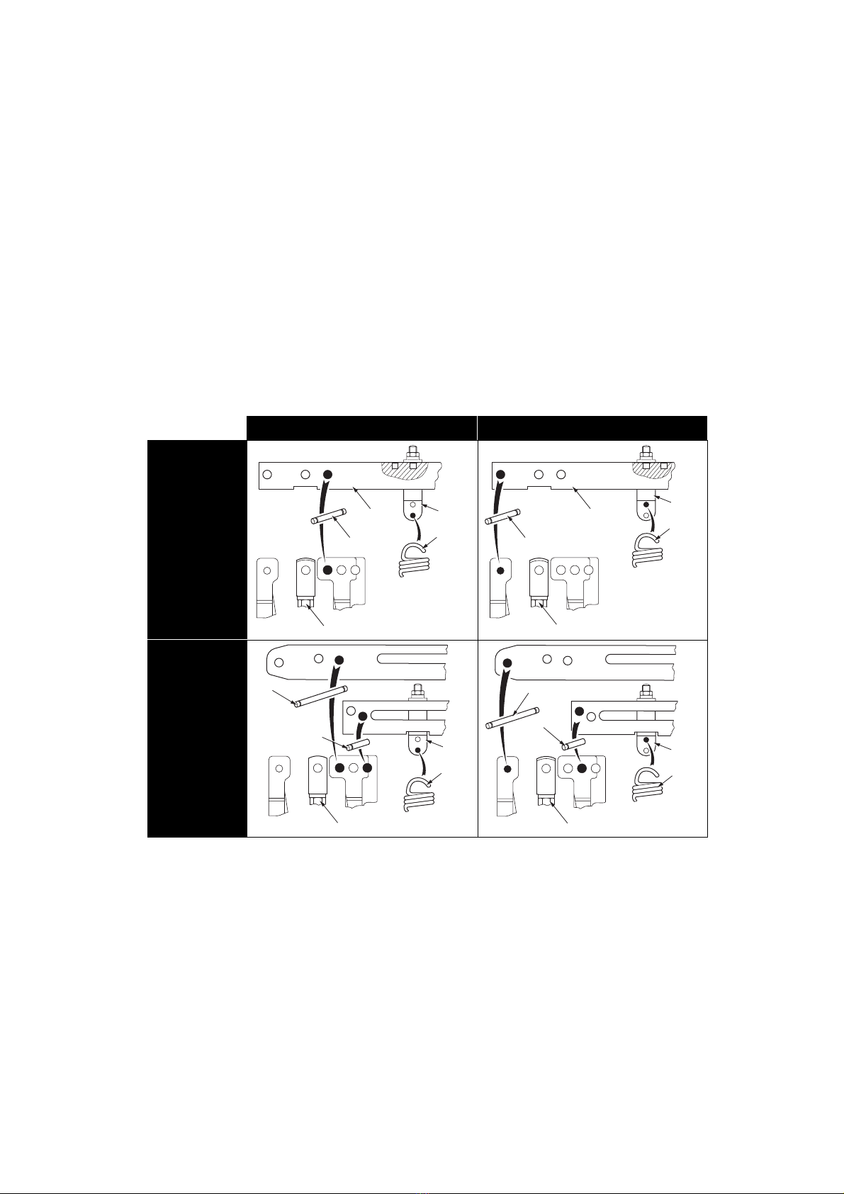
G. Refit the levers (113) making sure that the pin
(105) is fitted into the correct holes in the lever
and bracket for the new action of the actuator
(see figure 6). Fit the spring clamp (115) into the
corresponding lever hole.
Note: Ensure that the clevis is correctly
positioned before fitting the lever on the bracket.
H. Couple the plug stem clevis (104a) to the lever
(113) following the normal reassembly
procedure (step I. in the "Reassembly" section
on page 17). Then follow the same procedure as
for the VariPak 28002 adjustable-Cvvalve as
from step L.
2.5.2 VariPak 28002 adjustable-Cvvalve
(2 levers)
E. Remove retainer clips (112b) from each of the
two pins (184) and remove pins from lever (113)
and plug clevis (104a).
Note: This operation will be simplified by
relieving the load exerted on the plug clevis by
the conical compression spring (106). To do this
push against the plug stem end with a
screwdriver while driving out the pins.
F. Remove the two retainer clips (112a) from pin
No. 1 (105) and disengage it to uncouple lever
No. 1 from bracket (108). Loosen adjustment
knob (24) and slide it to the maximum Cvsetting.
Disengage the smooth end of the adjustment pin
(23) from the groove in lever No. 2 while
removing lever No. 1.
G. Drive out pin No. 3 (18) and remove lever No. 2
(22) from the bracket.
H. Remove the two screws (26) and refit Cv
adjustment plate (25) after turning it round to
comply with the new action.
I. Refit levers No. 1 and 2 in sequence, making
sure that pins (105) and (108) are fitted into the
correct holes in the levers and bracket for the
new action of the actuator (see figure 6).
Caution: The valve must be isolated and
pressure vented before disassembly.

Instruction No. EH 45004 E
05/2004
9
Note: Ensure that the clevis is correctly
positioned before fitting the lever No. 1 on the
bracket (108).
J. Reset adjustment knob (24) to the minimum Cv
position.
K. Couple plug stem clevis (104a) to lever No. 1
following the normal reassembly procedure (step
L. in the "Reassembly" section on page 17).
L. Hook spring (114) in the appropriate hole in
spring clamp (115) (see figure 6).
M. Admit supply and signal pressures and complete
calibration. Refit cover (110) using the two
screws (109). If the valve is equipped with a
handwheel, refit the cover and turn the
handwheel clockwise so that it engages in lever
arm stop (122). Tighten cover screws (109).
N. Put the valve back into service.
Note:
- When replacing an Air-to-Close actuator with an
Air-to-Open actuator, do not forget to neutralize the
limit stop by screwing it down at the bottom of the
piston.
- When replacing an Air-to-Open actuator with an
Air-to-Close actuator, set the limit stop to the
opening position.
AIR-TO-CLOSE ACTUATOR AIR-TO-OPEN ACTUATOR
VariPak 28001
with
single lever
VariPak 28002
with
adjustable Cv
(2 levers)
* Only with type 7700 positioner
Figure 6 - Identification of lever pivot pin holes
115
114
113
105
104a
*
*
115
114
113
105
104a
*
*
115
114
18
105
104a
*
*
No. 1
No. 2
115
114
18
105
104a
*
*
No. 1
No. 2

Instruction No. EH 45004 E
05/2004
10
3.1 PRELIMINARY STEPS
A. Before installing the valve in the line, remove all
traces of foreign material from the piping such as
welding chips, scale, oil, grease, etc.
B. Note down all the data given on the serial plate.
C. For valve inspection without interrupting process
operation, a hand-operated stop valve will be
required on either side of the VariPak, together
with a hand-operated throttling valve mounted on
a bypass line.
3.2 VALVE INSTALLATION (Figures 7, 8
and 9)
Connections: The body of the ANSI Class 1500*
rated VariPak valve can be:
- Bolted between 25 mm (1") pipe flanges
machined to standards ISO-PN 10 to PN 250
(ANSI 150 - 300 - 600 - 900 and 1500 lb).
Use ASTM A 193 Gr B 7 (or equivalent) carbon
steel bolting for temperatures between -29° and
+350 °C. For corrosive or cryogenic service, use
ASTM A 193 Gr B8 strain-hardened stainless
steel. All the line bolting required for installation
can be supplied by Masoneilan on request.
- Connected by 25 mm flanges machined to
standards ISO-PN 20, 50 and 100 (ANSI 150,
300 and 600 lb).
Fit gaskets compatible with service conditions
between the valve body and the pipe flanges.
The VariPak valve body can be supplied on
request with 1/2", 3/4", or 1" NPT threaded ends.
Apply PTFE tape or a sealing compound
compatible with the process to the threaded pipe
ends.
Alignment: This valve is small and light, making it
easy to install on the piping. Support the valve body
when fitting studs. Suitably shaped bosses are
provided to center the valve in the line and prevent
rotation before the studs are finally tightened.
The valve must always be installed with "flow
tending to open". The flow arrow on the valve body
must be pointing in the direction of flow. Fit the bolts
and tighten in criss-cross fashion.
3. Installation
* Except in the case of valve bodies designed for maximum Cvof 3.8: ANSI class
Figure 7 - VariPak flanged connection
Figure 8 - VariPak flanged body
Figure 9 - VariPak screwed connection (option)

Instruction No. EH 45004 E
05/2004
11
Insulation: If the valve is to be insulated, ensure that
the insulation does not exceed the shaded area
shown in figure 10 below.
3.3 PNEUMATIC AND ELECTRICAL
CIRCUIT (Figures 3, 11 and 12)
-On-off valve: connect the air supply line directly
to the 1/8" NPT threaded connection in
diaphragm cover (137).
-Control valve with 7700P positioner (air signal):
connect the supply and instrument signal lines to
the appropriate connections on the manifold
block (144) (figure 11). Use 4 x 6 mm (1/4" O.D.)
tubing.
-Control valve with 7700E positioner (electrical
signal): connect the manifold block (144) air
supply line and make the electrical connection
for the I/P module (20) (figure 12).
Use 4 x 6 mm (1/4" O.D.) tubing for the air line.
Note: Check that the supply pressure is that
indicated on the serial plate.
7700P or 7700E positioners can be installed on both
VariPak 28001 single-lever and VariPak 28002
adjustable-Cvvalves.
3.4 LIMIT SWITCHES(Figure 13)
In some cases, limit switches can be provided for the
VariPak valve, on request. These are wired and
adjusted in the factory to customer order. The black
wire is connected to either the normally open or
normally closed terminal of the upper limit switch.
The black and white wire is connected to the
common terminal of this switch. The red wire is
connected to either the normally open or normally
closed terminal of the lower limit switch.
The red and white wire is connected to the common
terminal of this switch. To adjust limit switches,
loosen their fasteners and move the valve to the
required position. Adjust the position of the switch
until it trips. Tighten fasteners (160 - 161 - 162).
Figure 10 - Insulation limit for a VariPak valve
Figure 11 - Connections with 7700P positioner
Instrument
1/4 NPT
Alimentation
1/4 NPT
1/8 NPT
137
144
1/8" NPT
connection
1/4" NPT supply
connection
1/4" NPT instument
signal connection
Alimentation
1/4 NPT
1/8 NP
T
137
144
Connexion
Ølectrique
signal
Figure 12 - Connections with 7700E positioner
1/8" NPT
connection
1/4" NPT supply
connection
Electrical
signal
connection
160-161-162 Micro-rupteur
supØrieur
Micro-rupteur
infØrieur
159
124
163-164
Figure 13 - Limit switch installation
Upper limit
switch
Lower limit
switch

Instruction No. EH 45004 E
05/2004
12
VariPak valves are factory-calibrated according to
the components specified in the customer order. If
for any reason this calibration has been disturbed
(e.g. after changing from direct to reverse valve
action, or replacing the plug and seat ring), all or
some of the adjustments below must be carried out
in the following order:
-Piston rod clevis (104b) adjustment.
-Plug stem adjustment.
-Limit stop adjustment.
-Cvadjustment.
-Positioner start-up pressure adjustment.
4.1 PISTON ROD CLEVIS ADJUSTMENT
4.1.1 Adjusting the piston rod clevis on the
VariPak 28001 single-lever valve (Figures
14 and 26)
With the piston resting against diaphragm cover
(137), turn clevis (104b) so that the top of actuator
bracket (108) is 0.5 mm to 1 mm from the bottom of
indicator (126). A shim will simplify this operation.
Admit enough air pressure to disengage locknut
(125) and tighten it against indicator. Check that
indicator (126) is correctly positioned. Release air
pressure.
4.1.2 Adjusting the piston rod clevis on the
VariPak
28002 adjustable-C
v
valve (Figures
14 and 27)
With the piston resting against diaphragm cover
(137), turn clevis (104b) so that the top of the
actuator bracket (108) is 0.5 mm to 1 mm from the
bottom of indicator (126). A shim will simplify this
operation.
Couple lever No. 2 (22) in this clevis position. Admit
enough air pressure to disengage locknut (125) and
tighten it against the indicator. Check that indicator
(126) is correctly positioned. Release air pressure.
4.2 PLUG STEM ADJUSTMENT
4.2.1 Adjusting the plug stem on the VariPak
28001 single-lever valve (Figures 15, 16
and 26)
A. Loosen nut (103) and turn the plug stem using a
screwdriver while blocking clevis (104a) until the
clevis is in the position shown in figure 15. Lock
nut (103).
This adjustment is only required if the piston
(131) has been removed.
In this case, it should be carried out during
reassembly, before coupling the lever (113) to
the clevises (chap. MAINTENANCE -
Reassembly. step H., page 17).
4. Calibration
104b
126
125
108
131
137
0,5 1m
m
Figure 14 - Piston rod clevis (104b) adjustment
0.5 to 1 mm
This adjustment is only required if the piston
(131) has been removed.
In this case, it should be carried out during
reassembly, before coupling the levers (21)
and (22) to the clevises (chap. MAINTENANCE
- Reassembly. step K., page 17).
This adjustment should be carried out during
reassembly, before coupling the lever (113) to
the clevises.
Figure 15 - Presetting the plug stem position
A 2 / 3 mm
(cote thØorique 2,3 mm)
B
2/3 mm
(theoretical dimension 2.3 mm)

Instruction No. EH 45004 E
05/2004
13
B. Fit lever (113) with spring clamp (115)
positioning hole facing upwards, fit pin (105) into
hole A, then fit pin (18) into clevis (104a).
Note: All pins should be greased slightly before
fitting.
C. Press the lever on the actuator side to check for
plug/seat ring leaks at ∆P 3.5 barg (50 psig). If
the valve is equipped with a handwheel, lever
(113) should not touch lever arm stop (122). If
the valve leaks, release the pressure at the inlet
and remove pin (18) of clevis (104a), then loosen
nut (103). Loosen the plug stem in order to move
the clevis up (104a). A complete turn moves the
position up by 1 mm. Then tighten the locknut
(103) again.
D.
Check that the distance between clevis (104b) pin
and the hole in lever (113) is approximately 2 mm.
If necessary, adjust the position of clevis (104a) to
obtain this distance, see figure 16. This value
provides the initial compression of actuator spring
(134).
E. Admit enough air pressure to the actuator to
drive piston clevis (104b) upwards. Couple the
clevis to lever (113) using pin (124).
F. Release the actuator pressure and repeat the
plug/seat ring leak test at ∆P 3.5 barg (50 psig).
Dimension A should be the same as in figure 16 .
Release the valve pressure once this step is
completed.
4.2.2 Adjusting the plug stem on the VariPak
28002 adjustable-Cvvalve (Figures 27, 28
and 29)
Once all the coupling operations are completed,
proceed as follows:
A. Admit enough pressure to the actuator to drive
out the piston rod far enough to place a shim
under the indicator (126). Use a 1.5 mm shim for
an Air-to-Open actuator, and a 25 mm shim for
an Air-to-Close actuator. Release the air
pressure after inserting the shim.
B. Loosen adjustment knob (24) and slide it along
lever No. 1 to the maximum Cvposition on
adjustment plate (25). Fully tighten adjustment
knob (24).
C. Loosen locknut (103) and, using a screwdriver,
turn the plug stem until the plug is just touching
the seat ring. If the valve has been removed from
the pipe, a bubble test can be performed on the
calibration bench to obtain a very accurate
adjustment. Using the screwdriver to hold the
plug stem in position, tighten locknut (103)
against clevis (104a).
D. Admit air pressure again to remove the shim,
then release the pressure.
Note: On an Air-to-Open actuator, shim thickness
may be increased or decreased by one or two-tenths
of a millimeter to ensure that levers No. 1 and 2 are
perfectly parallel and to obtain the required tightness
on closing, especially for very low Cvvalues
(Cv< 0.10).
4.3 LIMIT STOP ADJUSTMENT
(Figure 5)
VariPak valves include a limit stop to prevent
damage to the plug and seat ring and/or plug stem in
the event of actuator or handwheel overstroke. This
device consists of a nut (180) acting as a stop,
screwed onto the piston rod inside the spring
chamber, and a locknut (181).
If necessary, this device should be adjusted
immediately after plug stem adustment (see section
4.2).
A. Remove the shim (for VariPak 28002 adjustable-
Cvvalve only) and admit sufficient supply
pressure to close the valve. Turn locknut (181)
on the piston rod until it touches locknut (125).
Turn limit stop (180) until it just touches the
inside of actuator bracket (108).
B. Hold the limit stop with a 12 mm wrench and
tighten locknut (181). Release the air pressure.
2 mm
AAir ouvre = 15 mm
Air ferme = 17 mm
Figure 16 - Adjusting the lever (113)
Air to open = 15 mm
Air to close = 17 mm
At this closing point where the plug is not
tightened onto the seating, the slides of
levers No. 1 and 2 should be perfectly parallel.
This characteristic makes it possible to
change the adjustment knob (24) position
later to obtain the required real Cvvalue.

Instruction No. EH 45004 E
05/2004
14
4.4 VARIPAK 28002 CvADJUSTMENT
This adjustment is carried out by moving adjustment
knob (24) along adjustment plate (25) fastened to the
top of lever No. 1 (21). See section “Adjusting the Cv
of a Varipak 28002 valve for each plug and seat ring
combination”, page 7.
4.5 POSITIONER START-UP PRESSURE
ADJUSTMENT
(Figures 7, 25, 26 and 27)
A. Connect the air supply and signal lines to the
7700P or 7700E (with electrical signal)
positioner.
B. Set the supply pressure according to the valve
Cvvalue (see the table in figure 3).
C. Set the signal to the minimum value for an Air-to-
Open actuator, and to the maximum value for an
Air-to-Close actuator. Turn take-up screw (116)
until the piston rod just begins to move. Tighten
locknut (117).
5.1 ACTUATOR DIAPHRAGM REMOVAL
(Figures 17, 24, 25, 26 and 27)
A. Unscrew the two pressure connection nuts
(138a) and pull tubing (140) out. Remove the
four cap screws (139) and diaphragm cover
(137). Remove the worn diaphragm. Form new
diaphragm (136) and fit it on the piston as shown
in figure 17. Fit the diaphragm roll into the
bracket groove. Take care not to twist or bend
the diaphragm during replacement. Refit
diaphragm cover (137) with the four screws
(139) and reconnect the tubing with the two
pressure connection nuts (138a). Check that all
connections are leaktight.
5.2 ADDING PACKING RING (Figures
18, 26 and 27)
A. Before adding packing ring, the valve must be
isolated and all pressure released. Remove
packing flange nuts (8b), lift the packing flange
and follower, and insert a new packing ring.
Tighten nuts (8b) finger tight and then tighten
one full turn with the wrench.
Caution: Always ensure that there is no
pressure in the valve, actuator, or positioner
before maintenance or disassembly.
5. Maintenance
Figure 17 - Diaphragm replacement
Figure 18 - Adding a packing ring

Instruction No. EH 45004 E
05/2004
15
5.3 DISASSEMBLY (Figures 5, 24, 25,
26, 27, 28 and 29)
In some cases, it may be necessary to disassemble
the VariPak valve, for example, to replace the
plug/seat ring assembly (fitting new parts or
changing the maximum Cvvalue) or to change the
packing rings when the maximum Cvis less than 0.6.
Note: If the maximum Cv
≥
0.6, a quick change
method can be used to avoid disassembling the
valve (see page 18).
A. Loosen cover screws (109) and remove cover
(110). If the valve is equipped with a handwheel,
loosen cover screws (109) and handwheel lock
(121), then turn handwheel (120) counter-
clockwise to release cover (110).
Disassembly procedure for the VariPak 28001
single-lever valve:
B. Unlock nut (117) and completely loosen screw
(116). Remove spring clamp (115) from lever
(113) and remove spring (114) from the
positioner.
C. Remove the two retainer clips (112c) from pin
(124) and disengage the pin to uncouple piston
clevis (104b) from lever (113).
Note: To simplify this operation, admit air
pressure to the actuator to drive the piston clevis
(104b) upwards, then release the air pressure.
D. Remove retainer clips (112b) from pin (18) and
disengage the pin from lever (113) and plug
clevis (104a).
E. Remove two retainer clips (112a) from pin (105)
and disengage the pin to uncouple lever (113)
from actuator bracket (108). Now proceed in the
same way as for the VariPak 28002 adjustable-
Cvvalve, as from step I.
Disassembly procedure for the VariPak 28002
adjustable-Cv valve:
B. Adjust the signal to close the valve. Change the
signal slightly so that the plug just moves off the
seat ring. Set adjustment knob (24) to the
minimum Cvposition.
C. Loosen locknut (103) and, using a screwdriver,
turn the plug stem one and three-quarter turns
counter-clockwise. Shut off signal and supply
pressure. Slightly tighten locknut (103) against
the clevis.
D. Completely loosen locknut (117) and screw
(116). Remove spring clamp (115) from lever No.
2 and remove balance spring (114) from the
positioner.
E. Remove the retainer clip (112b) from each of the
two pins (184) and disengage the pins from lever
No. 1 and clevis (104a).
Note: This operation will be simplified by
relieving the load exerted on the plug clevis by
the conical compression spring (106). To do this
push against the plug stem end with a
screwdriver while driving out the pins.
F. Remove the two retainer clips (112c) from pivot
pin No. 4 (124) and disengage the pin to
uncouple piston clevis (104b) from lever No. 2
(22).
G. Remove the two retainer clips (112a) from pivot
pin No. 1 (105) and disengage the pin to
uncouple lever No. 1 from the actuator bracket
(108). Disengage the smooth end of adjustment
pin (23) from the groove in lever No. 2 and
remove adjustment knob (24) and adjustment
pin (23) from lever No. 1.
H. Drive out pivot pin No. 3 (18) and remove lever
No. 2 (22).
I. Hold the plug stem in place using a screwdriver
and unlock nut (103). Loosen clevis (104a) and
locknut (103). Remove spring button (102),
spring (106), and grommet plate (101).
J. Remove the two packing flange nuts (8b),
packing flange (10) and packing follower (9).
Remove the two bracket mounting nuts (8a) as
well as the bracket (108).
K. Using a packing hook, remove as many packing
rings (6) as possible from the packing box.
Remove safety pin (11) and pull the plug stem to
remove the packing spacer (5), the plug and its
stem and, if necessary, the rest of the packing.
L. Using a 9/16" or 14 mm piece of hex stock and a
wrench, unlock and pull out the seat-ring retainer
(4).
M. Remove seat ring (3) and gasket (2) using a
hook made from steel wire, approx. diameter
3 mm. Carefully fettle the hook end.
Note:
- The seat-ring of VariPak valves with Cvmax.< 0.10
consists of two parts: the seat ring proper (3e), and
a spacer (3f). These parts have a small orifice and so
cannot be removed using a hook. It is therefore
necessary to remove the body from the pipe and turn
it over and, if necessary, hit the bottom with a
wooden mallet. If the seat ring (3a) is jammed in its
housing, it can be removed by inserting a
screwdriver through the outlet orifice.
Caution: The valve must be isolated and
pressure vented before disassembly.

Instruction No. EH 45004 E
05/2004
16
- VariPak valves with Cvmax. 3.8 do not have seat-
ring gaskets (2).
5.4 REASSEMBLY (Figures 5, 15, 19, 20,
24, 25, 26, 27, 28 and 29)
Before reassembly, thoroughly clean the inside of
the valve body and parts, paying particular attention
to gasket seating surfaces and contact surfaces.
Make sure to use a new seat-ring gasket (2) and new
packing (6) during reassembly.
A. Insert a new seat-ring gasket (2) into valve body
(13), then fit seat ring (3), making sure that the
gasket is correctly centered on the seat-ring
shoulder. Turn it so that one of its ports is lined
up with the valve body outlet orifice.
Note: If the maximum Cvis less than 0.10, first fit
the seat ring (3e) on the new gasket (2), taking
the same precautions as above. Then fit the
spacer (3f), turning it so that one of its ports is
turned towards the body outlet orifice.
VariPak valves with a maximum Cvof 3.8 do not
include a seat-ring gasket (2).
B. Carefully apply Never Seez grease or equivalent
to the threads and bottom of the seat-ring
retainer (4). Using a 9/16" or 14 mm piece of hex
stock and a wrench, torque the retainer to 59 ft-
lb or 8 daN.m for stainless-steel reinforced
graphite gaskets or 40 ft-lb or 5.5 daN.m for
glass-filled PTFE gaskets (see figure 19).
Note: Torque the retainer to 30 ft-lb or 4 daN.m
for valves with a maximum Cvof 3.8.
C. Insert the plug and stem assembly into the seat
ring. For valves with a maximum Cv< 0.10,
check that there are no friction points in the plug
stroke. If a friction point is detected, loosen
retainer (4) and reposition seat ring (3e) until the
stem slides smoothly. Fit spacer (5), turning it so
that one of its holes is aligned with safety pin (11)
hole in the valve body.
Note: For valves with a maximum Cvless than
0.10, check that the retaining ring (182) is fitted
on the plug before fitting the plug in the spacer
(3f). If the retaining ring is worn or damaged,
replace it.
D. Wind two layers of PTFE tape around the safety
pin (11). Screw the pin into the bonnet five
and a half to six turns as from the thread
engagement point.
Note: To determine the thread engagement
point:
- Screw the safety pin about one turn.
- Pull the safety pin out while unscrewing it.
E. Fit the packing, making sure that the skive cut of
each packing ring is located 120° away from the
that of the adjacent ring. Push the rings down
slightly using a 1/2" sch., size 160 tube. Fit the
packing follower (9) onto the plug stem.
F. Fit actuator bracket (108) and secure it with two
nuts (8a). Slip packing flange (10) onto plug
stem. Handtighten the two packing flange nuts
and add one full turn with the wrench.
G. Fit, in the following order, grommet plate (101),
conical compression spring (106) and its spring
button (102) (see position in figure 26 and 27).
Screw nut (103) and clevis (104a) on the plug
stem.
Adjust the nut and clevis without locking them
together until the clevis holes are positioned
approximately:
- 2.3 mm below the alignment of the pin holes
in the actuator bracket (108) for the VariPak
28001 single-lever valve (see figure 15).
- 1.5 mm above the alignment of the pin holes
in the actuator bracket (108) for the VariPak
28002 adjustable-Cvvalve (see figure 20).
Note: Measuring this distance can be simplified
by fitting pins (105), (184) and (18) into their
holes.
Figure 19 - Tightening the seat-ring retainer (4)

Instruction No. EH 45004 E
05/2004
17
Reassembly procedure for the VariPak 28001
single-lever valve (continued):
H. Couple lever (113) to actuator bracket (108)
using pin (105) and the 2 retainer clips (112a).
Ensure that the holes in lever (113) where spring
clamp (115) is fitted is located above.
Note: Check that the clevis (104a) is correctly
positioned before fitting the lever (113) on the
actuator support (108).
To identify the position of the lever connecting holes
and the spring clamp (115) attachment hole, with
respect to the required action, see figure 6.
I. Couple clevis (104a) to lever (113). To do this,
press the end of the plug stem with a screwdriver
until the holes in the clevis and lever are aligned.
Couple using the pin (18) and retainer clips
(112b).
Note: Slightly grease all pins before fitting.
Perform the adjustment operation described in
"Calibration", section 4.2.1, page 12.
J. If piston rod clevis (104b) has not been disturbed
during disassembly, couple it to the end of lever
(113) by admitting air pressure to the actuator to
drive clevis (104b) upwards. Couple the clevis to
lever (113) using pin (124) and two retainer clips
(112c).
Note: If the clevis (104b) has been disturbed,
proceed with adjustment and coupling as described
in "Calibration", section 4.1.1, page 12.
K. Release the pressure from the actuator and
check tightness again (see "Calibration", section
4.2.1, page 12). Then continue from step M. of
the VariPak 28002 procedure.
Reassembly procedure for the VariPak 28002
adjustable-Cvvalve (continued):
H. Couple lever No. 2 (22) to the actuator bracket
(108) using pin (18). Ensure that the hole in lever
No. 2 where spring clamp (115) is fitted is located
above and in line with balance spring (114).
I. Fit adjustment pin (23) in the slide of lever No. 1
and screw adjustment knob (24) on its threaded
end. Insert the smooth end of pin (23) into the
groove in lever No. 2 and place lever No. 1 on
support bracket (108). Couple lever No. 1 to
actuator bracket (108) using pin (105) and two
retainer clips (112a).
Note: Check that the clevis (104a) is correctly
positioned before fitting lever No. 1 on the actuator
support (108)
To identify the position of the connecting holes of
levers No. 1 and 2 with respect to the required
action, see figure 6.
J. Set adjustment knob (24) to the minimum Cv
position.
K. If piston rod clevis (104b) has not been disturbed
during disassembly, couple it to the end of lever
No. 2 using pin (124) and two retainer clips
(112c).
Note: This operation will be simplified by applying air
pressure to the diaphragm (136) to set the piston rod
to an intermediate position, and by setting the
adjustment knob to a position where lever No. 2 is
most accessible. If the clevis (104b) has been
disturbed, proceed with adjustment and coupling as
described in "Calibration", section 4.1.1, page 12.
L. Couple clevis (104a) to lever No. 1. To do this,
press the end of the plug stem with a screwdriver
until the holes in the clevis and lever No. 1 are
aligned. Couple using the two pins (184) and
retainer clips (112b).
Note: The clips are inserted on the pins between the
sides of the clevis and lever No. 1.
M. Fully unscrew take-up screw (116) from spring
clamp (115), then fit clamp, after hooking
balance spring (114) first to the positioner spring
bracket of the diaphragm S/A (152), and then to
spring clamp (115).
Note: The spring clamp (115) has two holes. If an
Air-to-Open actuator is used, the spring must be
hooked to the top hole. If an Air-to-Close actuator is
used, the spring must be hooked to the bottom hole
(see figure 6).
1,5 mm
Figure 20 - Plug stem pre-adjustment
for VariPak 28002 adjustable-Cv
1.5 mm

Instruction No. EH 45004 E
05/2004
18
N. Admit the signal and supply pressure and
complete calibration. Refit cover (110) using the
two screws (109). If the valve is equipped with a
handwheel, refit the cover, then turn the
handwheel clockwise until it is engaged in lever
arm stop (122). Tighten cover screws (109).
O. If the valve body has been removed, reinstall it
taking the precautions given under "Valve
Installation" on page 10. Put the valve back into
service.
5.5 PACKING QUICK CHANGE
METHOD (ONLY FOR VALVES
WITH MAX. CvOF 0.6 TO 3.8)
(Figures 21, 26 and 27)
The quickest and easiest way to replace packing is
to remove the entire actuator from the valve body,
taking care not to modify the actuator setting. This
method is not recommended, however, for valves
with a maximum Cvless than 0.6 because of their
extremely fine plugs. For these valves, disassemble
the valve to replace the packing (see
"DISASSEMBLY", page 15).
Vent the valve pressure and proceed as follows:
A. Check that the plug is not resting on the seat
ring. For valves equipped with an Air-to-Open
actuator, admit air pressure under the diaphragm
and turn the handwheel to move the plug off its
seat ring.
B. Remove safety pin (11) from the valve body. The
safety pin stub engages with the hole in packing
spacer (5). The function of the safety pin and
spacer is to prevent the plug from being pushed
out if the actuator is accidentally removed while
the valve is still pressurized. The internal parts of
the valve cannot be removed unless the safety
pin is removed first. Remove the two packing
flange nuts (8b) and back off the two actuator
bracket mounting nuts (8a) as far as possible.
C. Remove the actuator-plug assembly from the
valve body, tapping it off with a block of wood
and mallet if necessary. Clean the packing box in
the valve body. Remove the worn packing, then
clean the plug stem thoroughly. Carefully fit new
packing rings around the stem, positioning the
skive cut of each ring 120° from that of the
adjacent ring.
D. Refit the actuator-plug assembly on the valve
body, taking care to:
- align hole in packing spacer (5) with safety pin
(11) hole,
- and refit the two mounting nuts (8a).
- Take extra care when guiding each packing
ring into the packing box.
E. Wind two layers of PTFE tape around the safety
pin. Screw the pin into the bonnet five and a
half to six turns as from the thread
engagement point.
Note: To determine the thread engagement point:
- Screw the safety pin about one turn,
- Pull the safety pin out while unscrewing it.
F. Refit the packing follower, packing flange, and
flange nuts (8b). Tighten the packing assembly
correctly. If the valve is equipped with an Air-to-
Open actuator, release the air pressure or turn
the handwheel to bring the plug back into contact
with the seat ring. Put back into service.
5.6 7700P OR 7700E POSITIONER
MAINTENANCE (Figures 22, 23, 24,
25, 26 and 27)
A. Disconnect the two pressure connection nuts
(138a) and pull tubing (140) out.
Figure 21 - Packing replacement
(for Cvmaxi ≥0.6)
Fit the new packing
Caution: Shut off the signal and supply
pressure. Isolate and depressurize the valve
body.

Instruction No. EH 45004 E
05/2004
19
B. Loosen the two cap screws (141a) and remove
manifold block (144), spring (158), gasket (146)
and its three O-rings, pilot valve assembly (155
to 157), shims (145), and O-ring (153).
C. Loosen locknut (117) and take-up screw (116),
unhook the spring clamp from lever (22) or (113).
D. Unscrew cap screws (141b) from positioner
block (147) and remove the positioner block from
the actuator bracket.
Remove screws (148) to separate positioner
diaphragm assembly (152) and spring (154) from
the positioner block. Examine all the parts and
replace if worn or damaged.
E. Refit positioner diaphragm assembly (152) and
spring (154) to positioner block and tighten
screws (148). Check that the small signal port O-
ring is in its recess in the diaphragm assembly.
F. Reinstall the block assembly on the actuator
bracket.
Note: When installing the positioner block (147), turn
it so that when the manifold block (144) is installed,
the gauge(s) is(are) facing in the right direction
(figure 22).
G. Check that gasket (146), three O-rings, and
seats are not worn or damaged and replace if
necessary.
H. Fit O-ring (153), shims (145), pilot valve
assembly, gasket (146) and its three O-rings,
spring (158) and manifold block (144). Tighten
the screws (141a), refit tubing (140) and tighten
pressure connection nuts (138a).
Note: The ports in gasket (146) must be aligned with
those in the positioner block (147).
To ensure correct positioner performance, check
that all gaskets are perfectly leaktight.
I. Hook spring clamp (115) to lever (22) or (113). In
the case of VariPack 28001 valve, see figure 6 to
position the spring clamp (115) according to the
actuator required action. Admit the supply
pressure and the signal. Set the start-up
pressure following the instructions given in the
"Calibration" chapter. Put back into service.
5.7 MAINTENANCE OPERATIONS
SPECIFIC TO THE 7700E
POSITIONER
A. Loosen screws (27) and remove I/P module (20).
Note: If damaged, the I/P module must be replaced.
B. Check that O-rings (28, 29 and 30) and their
seats are not worn or damaged.
Note: All worn or damaged parts must be replaced.
C. Fit O-rings (28, 29 and 30) in their recesses on
the I/P module (20). Refit I/P module (20) on
manifold block (144). Tighten screws (27).
Note: To ensure correct positioner performance,
check that all gaskets are perfectly leaktight.
Caution: Handle the shims carefully (145).
146
147
Figure 22 - Positioner assembly
Note how the positioner (147)
and gasket (146) are oriented
Positioner Signal
(Psi)
Spring ref.
No.
Spring color
code
7700P
3-15
or
6-30
or
3-27
114
154
Yellow
Red
3-9 114 White
154 Blue
9-15 114 White
154 Green
7700E 4-20 mA 114 Yellow
154 Red
Figure 23 - Color code for positioner springs
(114 and 154)
REFER TO ATEX INSTRUCTION MANUAL
No. 185977 FOR ALL MAINTENANCE ON THE
ELECTRICAL PARTS OF THE 7700E
POSITIONER.

Instruction No. EH 45004 E
05/2004
20
5.8 CONVERTING A 7700P
POSITIONER (PNEUMATIC) INTO A
7700E POSITIONER (ELECTRO-
PNEUMATIC)
A kit comprising the manifold block (144) and the I/P
module (20) is available from your local Masoneilan
representative or the Spare Parts Department.
Shut off the signal and supply pressure. Isolate and
depressurize the valve body.
A. Disconnect the two pressure connection nuts
(138a) and pull the tubing (140) out.
B. Loosen the two cap screws (141a) and remove
manifold block (144). The spring (158), gasket
(146) and the three O-rings, the pilot valve
assembly (155 to 157), shims (145), and O-ring
(153) do not need to be removed unless you
have new parts. Otherwise, simply check that
parts are in perfect condition before refitting.
C. If the parts mentioned above have been
removed, proceed as follows:
Fit the O-ring (153), shims (145), pilot valve
assembly (155 to 157), gasket (146) and the
three O-rings, the spring (158) and manifold
block (144) - I/P module (20). Tighten screws
(141a), refit tubing (140) and tighten pressure
connection nuts (138a).
Note: The ports in gasket (146) must be aligned with
those in positioner block (147).
To ensure correct positioner performance, check
that all gaskets are perfectly leaktight.
D. Hook spring clamp (115) to lever (22) (VariPak
28002) or (113) (VariPak 28001). In the case of
VariPack 28001 valve, see figure 6 to position
the spring clamp (115) according to the actuator
required action. Admit the supply pressure and
enable the electrical signal. Adjust the start-up
pressure following the instructions under
"Calibration". Put back into service.
REFER TO ATEX INSTRUCTION MANUAL
No. 185977 FOR ALL MAINTENANCE ON THE
ELECTRICAL PARTS OF THE 7700E
POSITIONER.
Caution: Handle the shims carefully (145).
This manual suits for next models
1
Table of contents
Other Dresser Control Unit manuals
Popular Control Unit manuals by other brands

Alfalaval
Alfalaval SMP-BCA instruction manual

Z-World
Z-World RabbitCore user manual

Astral Pool
Astral Pool HALO DOSER installation manual

Proportion-Air
Proportion-Air QL3 Series Installation & maintenance instructions

B meters
B meters RFM-TX1.1 manual

Technica Engineering
Technica Engineering TE-1437 user manual

SIGMA TEK
SIGMA TEK CP 112 instruction manual

Delta
Delta R3707 manual

Power Tec
Power Tec Regenerative Brushless DC Motor Control... Installation and operation instruction manual

Exor
Exor CDW10U2UL installation instructions

Thermarest
Thermarest TwinLock instructions

B meters
B meters RFM-LR1 quick start guide