Dresser Masoneilan 10000 Series User manual

Instruction Manual
EH10000
06/10
10000 Series
Double Ported
Globe Valves
Putting You In Control

Copyright
Masoneilan® is a registered trademark of Dresser, Inc. All information contained herein is believed to be accurate at the time of
publication and is subject to change without notice.
Copyright 2010 by Dresser, Inc. All rights reserved.
The following Instructions should be thoroughly reviewed and understood prior to installing, operating or performing
maintenance on this equipment. Throughout the text, safety and / or caution notes will appear and must be strictly
adhered to, otherwise, serious injury or equipment malfunction could result.
Table of Contents Page
1. INTRODUCTION .......................................................................................................................2
2. UNPACKING .............................................................................................................................2
3. INSTALLATION .........................................................................................................................2
4. AIR PIPING ...............................................................................................................................2
5. BODY DISASSEMBLY (REFER TO FIGURE 9) ..........................................................................3
6. MAINTENANCE / REPAIR .........................................................................................................3
6.1 SEAT RING REMOVAL ......................................................................................3
6.2 BUSHING REMOVAL ........................................................................................3
6.3 LAPPING SEATS ...............................................................................................3
6.4 PLUG STEM PINNING .......................................................................................4
6.5 PACKING BOX ..................................................................................................5
6.6 PACKING BOX (OPTIONAL LUBRICATION FIGURE 7) .....................................5
7. VALVE BODY REASSEMBLY ...................................................................................................6
Based on general field failure data and product design analysis, a useful life period of 25 years or longer can be expected for the 10000 series globe valves. To maximize the useful life of
the product it is essential to conduct annual inspections, routine maintenance and ensure proper installation to avoid any unintended stresses on the product. The specific operating
conditions will also impact the useful life of the product. Consult the factory for guidance on specific applications if required prior to installation.

Safety Information
Important - Please Read Before
Installation
Masoneilan 10000 Series Control Valve instructions contain
DANGER, WARNING, and CAUTION labels, where
necessary, to alert you to safety related or other important
information. Read the instructions carefully before installing
and maintaining your control valve. DANGER and WARNING
hazards are related to personal injury. CAUTION hazards
involve equipment or property damage. Operation of damaged
equipment can, under certain operational conditions, result in
degraded process system performance that can lead to injury
or death. Total compliance with all DANGER, WARNING, and
CAUTION notices is required for safe operation.
This is the safety alert symbol. It alerts you to potential
personal injury hazards. Obey all safety messages that
follow this symbol to avoid possible injury or death.
Indicates a potentially hazardous situation which, if not avoided,
could result in death or serious injury.
Indicates a potentially hazardous situation which, if not avoided,
could result in serious injury.
Indicates a potentially hazardous situation which, if not avoided,
could result in minor or moderate injury.
When used without the safety alert symbol indicates a
potentially hazardous situation which, if not avoided, could
result in property damage.
Note: Indicates important facts and conditions.
About this Manual
• The information in this manual is subject to change without
prior notice.
• The information contained in this manual, in whole or part,
shall not be transcribed or copied without Masoneilan’s
written permission.
• Please report any errors or questions about the information
in this manual to your local supplier.
• These instructions are written specifically for the 10000 Series
Control Valve, and do not apply for other valves outside of
this product line.
Warranty
Items sold by Dresser® are warranted to be free from defects
in materials and workmanship for a period of one year from the
date of shipment provided said items are used according to
Dresser recommended usages. Dresser, Inc. reserves the right
to discontinue manufacture of any product or change product
materials, design or specifications without notice.
This instruction manual applies to the Masoneilan
10000 Series
Control Valve.
The Control Valve and Actuator MUST BE:
• Installed, put into service and maintained by qualified
and competent professionals who have undergone
suitable training.
• Under certain operating conditions, the use of damaged
equipment could cause a degradation of the performance
of the system which may lead to personal injury or death.
• Changes to specifications, structure, and components
used may not lead to the revision of this manual unless
such changes affect the function and performance of the
product.
• All air supply to the actuator must be turned off.
• All surrounding pipe lines must be thoroughly flushed
to ensure all entrained debris has been removed from
the system.
Instructions EH10000 - 06/10
10000 Series Double Ported Globe Valves 1

Instructions EH10000 - 06/10
10000 Series Double Ported Globe Valves 2
1. Introduction
The following instructions are designed to assist maintenance
personnel in performing most of the maintenance required on
the 10000 Series valve.
Masoneilan has highly skilled service people around the
world available for startup, maintenance and repair of
our valves and component parts. In addition, a regularly
scheduled training program is conducted to train customer
service and instrumentation personnel in the operation,
maintenance and application of our control valves
and instruments. Arrangements for these services can be
made through your local Masoneilan Representative. When
performing maintenance use only Masoneilan replacement
parts. Parts are obtainable through your local Masoneilan
Representative. When ordering parts always include Model
and Serial Number of the unit being repaired. These
installation and maintenance instructions apply to all sizes
and ratings of the Masoneilan 10000 Series control valves,
regardless of the type of trim used. The model number,
size and rating of the valve are shown on the identification
tags located on the actuator. Refer to Figure 1 to identify
valve nomenclature.
2. Unpacking
Care must be exercised when unpacking the valve to prevent
damage to the accessories and component parts. Should any
problems arise, contact your Masoneilan Representative or
Sales Office.
3. Installation
The valve must be installed with the flow entering between the
seats. In addition, the upper plug must be installed so that the
larger of the two V-notches in the plug is oriented to face the
inlet of the valve.
3.1 Before installing the valve in the line, clean piping and
valve of all foreign materials, such as welding chips, scale,
oil, grease or dirt. Gasket surfaces should be thoroughly
cleaned to ensure leak-proof joints.
3.2 To allow for in-line inspection, maintenance and removal of
the valve without service interruption, provide a manually
operated stop valve on each side of the 10000 Series valve
with a manually operated throttling valve mounted in the
bypass line (See Figure 2).
Figure 2
3.3 The valve must be installed so that the control substance
will flow through the valve body in the direction indicated by
the flow arrow located on the body or the words in and out
stamped on end connections. In addition, see CAUTION
above.
3.4 Where insulation of the valve body is required, do not
insulate the valve bonnet.
4. Air Piping
The actuator is designed to accept 1/4" NPT air supply piping.
Use 1/4" OD tubing or equivalent for all air lines. If the air line
exceeds 25 feet in length or if the valve is equipped with volume
boosters, 3/8" tubing is preferred. All connections must be free
of leaks.
Do not exceed loading pressure indicated on the warning tag
located on the diaphragm cover. If no tag is present please
consult the actuator instruction manual or consult the factory.
2nd 2nd
0
5th
4th
3rd
1st
1
1st
8
Control Characteristics
3. Equal Percentage
6. Quick Opening
7. Linear
Body Series
10
87 Spring Diaphragm:
direct, Air to close
(fail open action)
88 Spring Diaphragm:
reverse, Air to open
(fail close action)
Actuator Type* Seat Type
2. Down
seating
Plug Type
1. Double Seat
Note: (*) For Valve Travel > 2.5" use Actuator Model 37/38.
Figure 1
Numbering System

Instructions EH10000 - 06/10
10000 Series Double Ported Globe Valves 3
5. Body Disassembly (Refer to
Figure 9)
Access to the internal components of the body should be
accomplished with the actuator removed. To remove the
actuator from the body, refer to the appropriate actuator
instruction ER8788.
Prior to performing maintenance on the valve, isolate the valve,
vent the process pressure, shut off supply and signal air lines
to the actuator. In addition, it is recommended that the bonnet,
body and bottom flange be marked in relation to each other so
the same orientation can be maintained during reassembly.
A. Remove stem lock nuts and travel indicator if applicable.
B. Remove packing flanged nuts (2), packing flange (3), packing
follower (19) from the bonnet.
C. Remove body stud nuts (11) from around the bonnet and
bottom flange.
D. Remove bonnet (6) bottom flange (10) gaskets (13) and plug
and stem subassembly (9, 1 and 8) from the body.
Note: If a new body gasket (13) is not available, care must
be taken to preserve the old gasket for reuse. Spiral wound
flexitallic gaskets are standard in the 10000 Series design,
and it is recommended that a new gasket be installed each
time the valve is disassembled.
E. Remove packing (17) and packing spacer (18) from the bonnet.
F. Inspect all parts for wear and service damage. If bushings
(14) must be removed from the bonnet or bottom flange, refer
to Section 6.2. After determining the maintenance required,
proceed to the appropriate section of these instructions.
6. Maintenance / Repair
The purpose of this section is to assist maintenance personnel
by suggesting methods of component maintenance which is
largely dependent on the tools and machine shop equipment
available. Each section should be read and understood before
proceeding.
6.1 Seat Ring Removal
Threaded seat rings (15 and 16) are installed tightly at the point
of manufacture and after years of service they are often difficult
to remove. To facilitate removal, seat ring wrenches can be
fabricated to engage the seat ring lugs and adapted to a shock
wrench (see Figure 3). If the ring is exceptionally resistant to
removal the application of heat or penetrating oil should be
helpful.
Figure 3
When using heating devices, ensure that proper safety practices
are observed. Such items as flammability and toxicity of
the controlled substance must be considered and proper
precautions taken.
6.2 Bushing Removal
The bushings (14) are press fit into the bonnet and bottom
flange, and do not normally require replacement. However,
should replacement be required, they can be pulled or machined
out. When machining the bushings out, care must be taken to
maintain proper dimensions and tolerances. These will be
furnished upon request.
6.3 Lapping Seats
Lapping is the process of working the valve plug against the
seat ring with an abrasive to produce a close fit. When valve
leakage becomes excessive, lapping becomes necessary.
The plug and seat ring seating surfaces should be free of large
dents, scratches and the contact surfaces of the seats should
be as narrow as possible. This may require dressing both parts
in a lathe. Both surfaces make an angle of 30˚ with the axis of
the plug (see Figure 4).
Figure 4
For the lapping operation, a good grade of fine grinding
compound is required. The compound would be mixed with a
small quantity of lubricant, such as graphite. This will slow the
cutting rate and prevent tearing of the seating surfaces. The
amount of lapping required depends on the materials, condition
of seating surfaces and accuracy of machining. If a short period
of lapping does not visibly improve seating there is usually no

Instructions EH10000 - 06/10
10000 Series Double Ported Globe Valves 4
advantage in continuing, as too much lapping may result in
rough seats. The only remedy is replacement or re-machining of
one or both parts. When lapping new plug and seat ring, begin
with medium compound and finish with fine.
Before lapping plug and stem must be true (see pinning
operation, section 6.4).
Note: Seat repair in a double seated valve is critical. In a
new valve the distance between the upper and lower seat
ring seats is established in manufacturing and only lapping is
required to make both parts close simultaneously. In the field,
it is best to lap the seats first. If one of the seats is damaged
beyond what is repairable by lapping, care must be taken to
maintain the original distance between the seats on both the
plug and seat rings. Therefore, when machining one seat
of the plug or one seat ring the other must be machined in
exactly the same way.
A. Clean body gasket surface areas.
B. When the seats have been removed, ensure that the sealing
surfaces in the body bridge and the threads are thoroughly
cleaned.
Note: A lubricant such as Chesterton 725 or a sealant
compatible with the process should be applied sparingly, to
the seat ring threads and sealing shoulder.
C. Install and tighten seat rings using fabricated wrench used for
removal. (See Figure 3).
Do not over tighten. Do not strike seat ring lugs, this could
distort the seat ring resulting in unwarranted seat leakage.
D. Install bottom flange (10), ensuring bottom bushing (14) is
in place and secure to the body using body stud nuts (12)
spaced equally apart. Fasten the bottom flange to the body
using only slight pressure and tighten evenly.
Do not tighten nuts to torque specifications at this time. The
bottom flange is used temporarily for guiding purposes.
E. Apply lapping compound at several spots equally spaced
around the seating areas of the plug.
F. Insert the stem and plug assembly carefully into the body
until it is seated.
G. Place bonnet (6) on the body and using body stud nuts (12),
spaced equally apart, fasten to the body using only slight
pressure and tighten evenly.
Do not tighten nuts to torque specifications at this time. The
bonnet is used temporarily for guiding purposes.
H. Insert two or three pieces of packing (17) into the packing
box to assist in guiding the stem and plug during lapping.
I. Screw a drilled and tapped rod with a tee handle onto the
plug stem and secure with a lock nut. (See Figure 5).
Note: As an alternative, drill a hole through a flat piece of
steel and fasten to the plug stem using two lock nuts.
Figure 5
J. Apply a slight pressure on the stem, rotating the stem in short
oscillating strokes eight to ten times.
Note: The plug should be lifted and turned 90˚ before
repeating step 10. This intermittent lifting is required to
keep the plug and seat ring concentric during lapping. After
completion of the lapping operation, remove body stud nuts
(12) from the bonnet (6) and bottom flange (10).
K. Remove bonnet (6) and bottom flange (10).
L. The seat rings, plug and internal components of the valve
must be cleaned of all lapping compound in preparation for
reassembly.
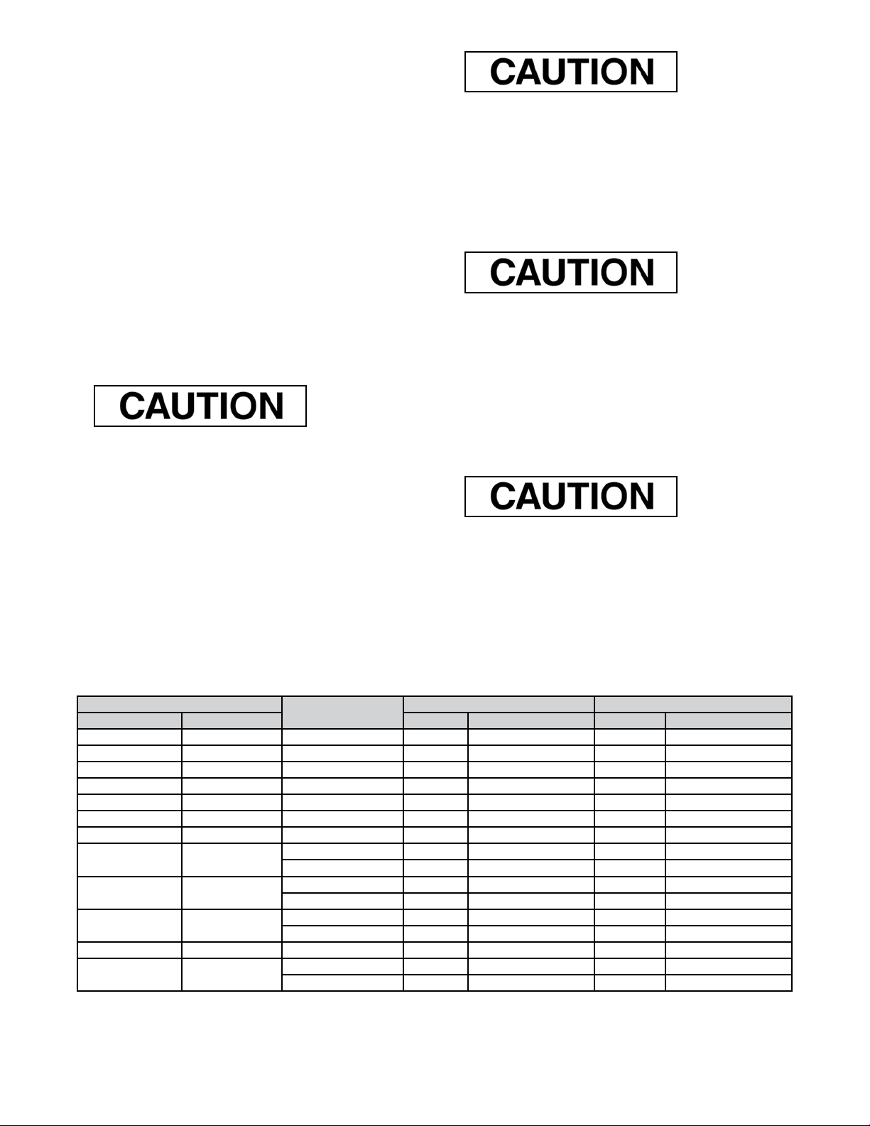
6.4 Plug Stem Pinning
Valve plug and stem assemblies are normally furnished as a
complete assembly in which case the installation involves no
problem. It is only necessary to lap the plug and seat ring and
assemble the valve. If it is necessary to replace the plug it is
recommended that a new stem be used. If the old stem must be
used, it is necessary to determine if the stem will be long enough
since the stem will require cutting. If the stem does not engage
the actuator stem by a minimum of one stem diameter, the old
stem should not be used. If it does not engage a minimum of
one stem diameter, proceed as follows.
Note: While pinning is being performed, care must be taken
not to damage the seating surface and plug guides.
A. Using a drift punch, drive out the old pin (8).
Note: If it is necessary to drill out the pin, a drill somewhat
smaller than the pin should be used and the remainder of
the pin driven out.
B. Unscrew the plug from the stem (counter clock-wise).
Figure 6

Instructions EH10000 - 06/10
10000 Series Double Ported Globe Valves 5
Figure 7
C. Cut off the stem directly above the pin hole. (See Figure 6).
D. Rethread the stem the original amount.
Note: The area of the plug stem marked X in Figure 8,
serves as a guide and must be checked to ensure a close
fit in the valve plug.
Stem
Dia.
Hole
Dia. "A" "B" "X"
Inches in mm in mm in mm
½0,188 4,78 1,250 31,75 0,50 12,7
5
/80,219 5,56 1,562 39,67 0,62 15,7
¾0,250 6,35 1,875 47,63 0,75 19,1
10,312 7,92 2,500 63,50 1,00 25,4
Figure 8
E. Screw the stem solidly into the plug.
Note: This can be checked by measuring the depth of
the pilot recess in the plug (X in Figure 8), and making a
reference mark on the stem the same distance from the
thread. When properly assembled, the reference mark
should be flush with the end of the guide section.
F. Place the plug guide on a V block and using a suitable size
drill, drill the stem using the hole in the plug as a guide.
G. Remove any burrs from the plug guide by making a slight
counter bore.
H. Select the correct size pin, apply a small amount of grease
on it and press into the hole.
Note: The pin must be recessed approximately 1/16" below
the plug guide surface.
I. After the plug has been pinned it should be placed in a lathe
to ensure it is running true. If it is not, strike the plug with a
soft faced mallot to straighten.
Note: The plug should be placed in a collet with the plug
guide against it and the plug should be struck.
6.5 Packing Box
Packing box maintenance is one of the principle chores of
routine servicing. Tightness of the packing is maintained by
packing compression. Compression is achieved by evenly
tightening the packing flanged nuts (2) against the packing
flange (3). Care must be taken not to over tighten, as this could
prevent smooth operations of the valve. If all compression is
used up and the valve leaks, new packing is required.
Valve must be isolated and pressure vented before performing
packing box maintenance.
Proceed as follows:
A. Loosen and remove packing flange nuts (2).
B. Raise packing flange (3) and packing follower (19) up the
valve stem.
C. Remove packing (17).
Note: Only the top pieces of the old packing are removable
by pulling them out the top of the bonnet. To remove all the
packing the bonnet must be removed. (See appropriate
section)
D. Replace packing. As a rule, 2/3 of the packing rings are
placed below the packing spacer, and 1/3 above.
Note: Ensure packing is inserted with skives 90˚ apart on
successive rings.
E. Replace packing follower (19) and packing flange (3).
F. Replace and tighten packing flange nuts (2).
Do not over tighten.
G. Put valve back in service and tighten packing only as much
as is necessary to stop leaking.
Note: In an emergency, string packing may be used as a
temporary repair only and must be replaced with the correct
packing as soon as possible.
6.6 Packing Box (Optional Lubrication Figure 7)
In some applications, packing boxes are designed for use with
a lubricator. The lubricator is provided with a ball check valve
to present backflow of the process fluid. On some valves, an
isolating valve (67) is added for positive protection against
backflow. The lubricator (66) should be kept filled with the
specified lubricant and turned in firmly but not tightly. One or
two turns of the lubricator once every two weeks should suffice
to provide the desired seal. Lubricants are available through
your Masoneilan Representative or District Office. Replacement
of the packing (17) is accomplished in the same manner as the
standard lubricator box. Care must be taken to ensure that the
latern ring (18) is in line with the lube hole located in the bonnet.
As a rule, 2/3 of the packing rings are inserted below the lantern
ring and 1/3 above.

Instructions EH10000 - 06/10
10000 Series Double Ported Globe Valves 6
7. Valve Body Reassembly
It is possible to change the valve from down seating to up
seating or vice versa. However, the plug stem must be
re-pinned to the opposite end of the plug. (If at all possible, a
new stem should be used.) Then, simply invert the valve body
and reassemble. The tolerances and clearances explained in
this instruction apply to either seating direction.
After completion of the required maintenance, the valve should
be reassembled using the following procedures.
Note: If any of the following steps were completed during
maintenance proceed to the next step. If the bonnet, body
and bottom flange were marked in relation to each other,
remember to align these marks to obtain the same orientation.
A. Clean all gasket surfaces.
B. Apply a small amount of lubricant to the seat ring threads and
sealing shoulder and install.
C. Using seat ring wrench, fabricated for removal, tighten seat
ring only enough to ensure a seal.
Do not over tighten. Do not strike the seat ring lugs.
This could distort the seat ring, resulting in unwarranted seat
leakage.
Note: Valve seats must be lapped before final assembly
(See section 6.3).
D. Install bottom flange gasket (13) bottom flange (10) and
loosely install body stud nuts (11). Install stem and plug
assembly (1, 8 and 9).
The upper plug must be installed so that the larger of the
two V notches in that plug is in line with the inlet of the valve.
Placement of a witness mark on the stem may be helpful.
E. Install bonnet gasket (13), bonnet (6) and loosely install body
stud nuts (11).
Note: For ease of accessibility the bonnet should be
positioned so that the packing flange studs are at right
angles to the flow center line.
Refer to Figure 10 for proper bolt torque and tightening
sequence specifications. Additionally the plug must be
stroked manually while evenly tightening the body stud nuts
(11) around both bonnet and bottom flange to ensure proper
alignment and prevent binding between the plug guides and
the bushings.
F. Insert packing (17) and packing spacer (18).
G. Install packing follower (19) and packing flange (3).
H. Install packing flange stud nuts (2).
Do not tighten at this time. When placed in service they
should be tightened only enough to stop leaking.
I. Install stem lock nuts and travel indicator on plug stem.
J. Proceed to the appropriate actuator instructions for actuator
to body assembly.
Note: (*) It is extremely important to tighten stud nuts evenly and in the sequence shown otherwise damage to the
guides or bushings could occur.
Valve Size ANSI Class Studs Maximum Torque*
in mm Qty Size (in) ft. lbs. m.daN
¾ 20 600 6 ½-13 55 7,5
1 25 600 6 ½-13 55 7,5
1½ 40 600 6 ½-13 55 7,5
2 50 600 8 ½-13 55 7,5
3 80 600 8 5
/8-11 89 12
4 100 600 8 ¾-10 170 23
6 150 600 12 ¾-10 170 23
8 200 300 16 5
/8-11 89 12
600 20 ¾-10 170 23
10 250 300 16 ¾-10 170 23
600 16 11
/8-8 428 58
12 300 300 16 7
/8-9 236 32
600 16 1½-8 789 107
14 350 - - - - -
16 400 300 16 1¼-8 332 45
600 16 11
/5-8 789 107
Bolt Torque and Tightening Sequence*

Instructions EH10000 - 06/10
10000 Series Double Ported Globe Valves 7
Figure 9
Note: V-Port is shown 90° out of position. It must be installed as explained in Section 3.
Figure 10

Instructions EH10000 - 06/10
10000 Series Double Ported Globe Valves 8
Notes

Instructions EH10000 - 06/10
10000 Series Double Ported Globe Valves 9
Notes

www.dresser.com
Dresser Masoneilan
Dresser, Inc., Flow Technologies
10343 Sam Houston Park Drive
Houston, Texas 77064 U.S.A
T. +1-281-671-1640
F. +1-281-671-1735
E. sales@masoneilan.com
DIRECT SALES OFFICE LOCATIONS
About Dresser Masoneilan
Dresser Masoneilan, headquartered in Houston, Texas,
has been the leading global partner in process control
valves and solutions for more than 100 years. A business
segment of Dresser, Inc., the company delivers customized
products, services and diagnostic solutions for oil and gas,
process and power generation applications. www.dresser.
com
© 2010 Dresser, Inc. All rights reserved.
BELGIUM
Phone: +32-2-344-0970
Fax: +32-2-344-1123
BRAZIL
Phone: +55-11-2146-3600
Fax: +55-11-2146-3610
CANADA
Ontario
Phone: +905-335-3529
Fax: +905-336-7628
CHINA
Phone: +86-10-8486-4515
Fax: +86-10-8486-5305
FRANCE
Courbevoie
Phone: +33-1-4904-9000
Fax: +33-1-4904-9010
GERMANY
Viersen
Phone: +49-2162-8170-0
Fax: +49-2162-8170-280
INDIA
Mumbai
Phone: +91-22-8354790
Fax: +91-22-8354791
New Delhi
Phone: +91-11-2-6164175
Fax: +91-11-5-1659635
ITALY
Phone: +39-081-7892-111
Fax: +39-081-7892-208
JAPAN
Chiba
Phone: +81-43-297-9222
Fax: +81-43-299-1115
KOREA
Phone: +82-2-2274-0748
Fax: +82-2-2274-0794
MALAYSIA
Phone: +60-3-2161-0322
Fax: +60-3-2163-6312
MEXICO
Phone: +52-5-310-9863
Fax: +52-5-310-5584
THE NETHERLANDS
Phone: +31-15-3808666
Fax: +31-18-1641438
RUSSIA
Veliky Novgorod
Phone: +7-8162-55-7898
Fax: +7-8162-55-7921
Moscow
Phone: +7 495-585-1276
Fax: +7 495-585-1279
SAUDI ARABIA
Phone: +966-3-341-0278
Fax: +966-3-341-7624
SINGAPORE
Phone: +65-6861-6100
Fax: +65-6861-7172
SOUTH AFRICA
Phone: +27-11-452-1550
Fax: +27-11-452-6542
SOUTH & CENTRAL
AMERICA AND THE CARIBBEAN
Phone: +55-12-2134-1201
Fax: +55-12-2134-1238
SPAIN
Phone: +34-93-652-6430
Fax: +34-93-652-6444
UNITED ARAB EMIRATES
Phone: +971-4-8139-200
Fax: +971-4-8838-038
UNITED KINGDOM
Wooburn Green
Phone: +44-1628-536300
Fax: +44-1628-536319
UNITED STATES
Massachusetts
Phone: +1-508-586-4600
Fax: +1-508-427-8971
Corpus Christi, Texas
Phone: +1-361-881-8182
Fax: +1-361-881-8246
Dresser Direct
Deer Park, Texas
Phone: +1-281-884-1000
Fax: +1-281-884-1010
Dresser Flow Technologies
Houston, Texas
Phone: +1-281-671-1640
Fax: +1-281-671-1735
California
Phone: +1-562-941-7610
Fax: +1-562-941-7810
EH10000 06/10
About Dresser, Inc.
Dresser Inc. is a global leader in providing highly-
engineered infrastructure products for the global energy
industry. Leading brand names within the Dresser portfolio
include Dresser Wayne® retail fueling systems, Waukesha®
natural gas-fired engines, Masoneilan® control valves,
Consolidated® pressure relief valves, and ROOTS® blowers
and rotary gas meters. The company has manufacturing
and customer service facilities strategically located
worldwide and a sales presence in more than 150 countries.
www.dresser.com
Table of contents
Other Dresser Control Unit manuals