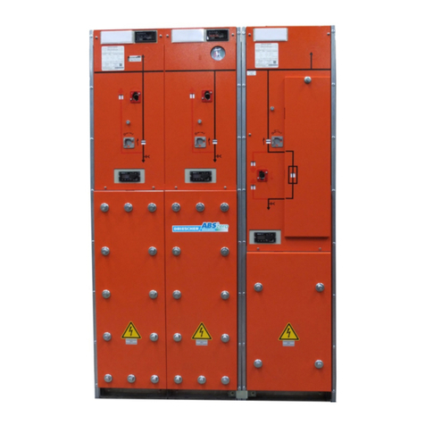
DRIESCHER-WEGBERG MINEX/G.I.S.E.L.A User manual

Nachrüstung der Magnetauslösung an gasisolierten Schaltan-
lagen Typ MINEX/G.I.S.E.L.A 12/24kV
Later assembly of magnet tripping at gas
insulated switchgear type MINEX/G.I.S.E.L.A 12/24kV
Zusatz zur Montage und Betriebsanleitung / Addition to Operating Manual
Mittelspannungs-Lastschaltanlage
Typ MINEX / G.I.S.E.L.A
Bemessungsspannung bis 24 kV
Bemessungsstrom 630A
Medium voltage switchgear
type MINEX / G.I.S.E.L.A
Rated voltage up to 24 kV
Rated current 630A
10/2007

DRIESCHER •WEGBERG
Nachrüstung Magnetauslösung / Later assembly of magnet tripping
2
INHALT
CONTENT
ALLGEMEINES..................................
3 GENERAL……………………………… 3
ÜBERSICHT DER EINZELTEILE…. 4 VIEW OF COMPONENTS…. 4
HUBMAGNET UND MELDESCHALTER……… 4
TRIP COIL AND SIGNAL SWITCH……………. 4
KLEMMLEISTE UND ZUBEHÖR………………. 5
TERMINAL STRIP & ACCESSORIES………... 5
MONTAGEFOLGE…………………... 6 ASSEMBLY SEQUENCE……………..
6
ANBAU HUBMAGNET………………………….. 7
MOUNTING TRIP COIL………………………… 7
ANBAU MELDESCHALTERBETÄTIGUNG… 9
MOUNTING SIGNAL SWITCH OPERATION…. 9
ANBAU MELDESCHALTER….………………… 11
MOUNTING SIGNAL SWITCH…………………. 11
KABELVERLEGUNG UND -ANSCHLUSS 13
CABLE INSTALLATION AND CONNECTION… 13
TECHNISCHE DATEN
MELDESCHALTER…………………
18
TECHNICAL DATA
SIGNAL SWITCH………………………
18
FEHLERSUCHE……………………… 18 TROUBLE SHOOTING………………..
18
KUNDENDIENST…………………….. 19 CUSTOMER SERVICE……………….. 19
Für diese Druckschrift behalten wir uns alle Rechte vor. Miss-
bräuchliche Verwendung, wie insbesondere Vervielfältigung
und Weitergabe an Dritte, ist - auch auszugsweise - nicht
gestattet. Angaben und Abbildungen unverbindlich. Änderun-
gen vorbehalten.
For the present documentation we reserve ourselves all rights.
An improper use and especially unauthorized reproduction and
divulgation to third parties – even of extracts – are not allowed.
The indications and illustrations are not binding. Modifications
are reserved.

DRIESCHER •WEGBERG
Nachrüstung Magnetauslösung /Later assembly of magnet tripping
3
DRIESCHER•WEGBERG, 2007 DRIESCHER•WEGBERG, 2007
Besonderer Hinweis:
Sie haben eine Schaltanlage Typ
MINEX / G.I.S.E.L.A erworben, an der die
Magnetauslösung nachgerüstet werden
soll. Diese vorliegende Montageanleitung
gibt lediglich spezielle Hinweise zur Mon-
tage dieses Gerätes und darf nur in Zu-
sammenhang mit der Montage- und Be-
triebsanleitung der Schaltanlage, in der
die allgemeine Handhabung und Bedie-
nung beschrieben ist, angewendet wer-
den
.
Special Hint:
You bought a switchgear type
MINEX / G.I.S.E.L.A on which a
magnet tripping shall be retro-fitted. This
manual only gives special hints regarding
the installation of this device and must be
used together with the
Operation and Assembly Manual of the
switchgear itself, in which the general
handling and operation is explained
.
Allgemeines
General
Die Magnetauslösung besteht aus mehreren
Einzelteilen, die sich an vorhandene Schalt-
felder nachrüsten lassen. Damit die Magnet-
auslösung korrekt funktioniert, muss zusätz-
lich ein Meldeschalterblock am Antrieb des
Lasttrennschalters angebaut werden. Der
Meldeschalterblock wird dabei als vormon-
tierte Einheit geliefert.
The magnet tripping consists of several
components that can be retro-fitted to existing
switchgear cubicles. For a correct function of
the magnet tripping, a signal switch set has to
be installed at the switch-disconnector
additionally. The signal switch set is delivered
as a pre-assembled unit

DRIESCHER •WEGBERG
Nachrüstung Magnetauslösung / Later assembly of magnet tripping
4
Übersicht der Einzelteile
View of components
Hubmagnet und Meldeschalter
Trip coil and signal switches
1.1 Hubmagnet 1.1 Trip coil
1.2 Zylinderschraube M3 1.2 Cylinder head screw M3
1.3 Federring A3 1.3 Spring washer A3
1.4 Sechskantschraube M6 x 16 1.4 Hexagonal bolt M6 x 16
1.5 Federring A6 1.5 Spring washer A6
1.6 Unterlegscheibe M6 1.6 Washer M6
1.7 Meldeschaltereinheit, vormontiert mit
6 Meldeschaltern
1.7 Signal switch set, pre-assembled with
6 signal switches
1.8 Distanzring 1.8 Distance ring
1.9 Unterlegscheibe M8 1.9 Washer M8
1.10
Exzenterscheibe 1.10
Excentric
1.11
Betätigungsblech 1.11
Operating sheet
1.12
Sechskantmutter M6 1.12
Hexagonal nut M6
1.4
1.5
1.7
1.7
1.6
1.1
1.8
1.4
1.2
1.3
1.9
1.6
1.5
1.10
1.12
1.11

DRIESCHER •WEGBERG
Nachrüstung Magnetauslösung /Later assembly of magnet tripping
5
Klemmleiste und Zubehör
Terminal strip and accessories
2.1 Schutzschlauch 1m 2.1 Protection tube 1m
2.2 Kabel H05V-K 1x0,75 (nicht enthalten) 2.2 Cable H05V-K 1x0,75 (not included)
2.3 Stecker 0,5-1,0² 2.3 Plug 0,5-1,0²
2.4 Flachsteckhülsen 0,5-1,0² 4,8 x 0,5 2.4 Flat pin bushings 0,5-1,0² 4,8 x 0,5
2.5 Aderendhülsen (nicht enthalten) 2.5 Cable-end sleeves (not included)
2.6 Klemmenbeschriftung 1-10 2.6 Clamp labelling 1-10
2.7 Brücke für Klemmen MBK 2,5 2.7 Link for clamps MBK 2,5
2.8 Endplatte für Klemmen MBK 2,5 2.8 End plate for clamps MBK 2,5
2.9 Endhalter für Klemmen MBK 2,5 2.9 End holder for clamps MBK 2,5
2.10
Klemmen MBK 2,5 2.10
Clamps MBK 2,5
2.11
Kondensator Fa. Erox Rita, 330 nF 2.11
Capacitor Messrs. Erox Rita, 330 nF
2.12
Kabelbinder 2,5x100 (nicht enthalten) 2.12
Cable binder 2,5x100 (not included)
2.13
C-Schiene 2.13
C-rail
2.14
Blindnieten 2.14
Blind rivets
Die Positionen 2.2, 2.5 und 2.12 sind nicht im
Lieferumfang enthalten.
Items 2.2, 2.5 and 2.12 are not included in our
scope of delivery (local part).
2.1 2.2
2.3 2.4 2.5 2.6 2.7
2.8
2.9
2.10
2.11
2.12
2.13 2.14

DRIESCHER •WEGBERG
Nachrüstung Magnetauslösung / Later assembly of magnet tripping
6
Montagefolge
Assembly sequence
Schalten Sie die Anlage gemäß der Mon-
tage- und Betriebsanleitung spannungs-
frei. Während der Montage der Magnet-
auslösung ist es notwendig, den Last-
trennschalter sowie den Erdungsschalter
ein- und auszuschalten, um die Installati-
on zu überprüfen. Dabei haben alle mit
diesem Arbeitsschritt befassten Personen
unbedingt dafür zu sorgen, dass nach
dem Ausschalten des Erdungsschalters
keine Spannung zugeschaltet werden
kann und die Anlage bis zur Beendigung
der Arbeiten spannungsfrei bleibt!
Isolate the switchgear according to the
Operating and Assembly Instruction. During
the installation of the magnet tripping it is
necessary to switch ON and OFF the
earthing switch and the switch-disconnector
in order to check the installation. In doing
so, all persons involved with this working
step have to make sure that no voltage can
be supplied to the switchgear after the
earthing switch is switched OFF and that the
switchgear keeps isolated till the end of
work!
Schalten Sie die Lasttrennschalter aus und
die Erdungsschalter ein.
Operate switch-disconnector OFF and earthing
switch ON.
Halten Sie die beschriebenen Montage-
schritte genau ein, um eine ordnungs-
gemäße Funktion der Magnetauslösung zu
gewährleisten.
Strictly follow the described installation steps,
in order to guarantee an adequate function of
the magnet tripping.

DRIESCHER •WEGBERG
Nachrüstung Magnetauslösung /Later assembly of magnet tripping
7
Anbau Hubmagnet
Mounting trip coil
Entfernen der Frontblende des Transforma-
torfeldes (1) und der Kabelfelder (2)
Remove the front cover of the transformer
cubicle (1) and of the cable cubicles (2)
Die Sicherungsblende (3) wird entfernt. An-
schließend werden die Schrauben der Front-
blenden (Transformatorfeld und linkes Kabel-
feld) gelöst und diese herabgenommen. Die
Schrauben sind mit Gummiringen gesichert
und verbleiben in der Frontblende.
Remove the fuse cover (3). After that, loosen
the bolts of the front covers (transformer cubi-
cle and left cable cubicle) and detach them.
The bolts are secured by means of rubber rings
and will remain in the front cover.
3
1
2 2

DRIESCHER •WEGBERG
Nachrüstung Magnetauslösung / Later assembly of magnet tripping
8
Den Hubmagnet (1.1) von oben in den An-
trieb des Lasttrennschalters schieben. Dabei
zeigen die Bohrungen für die Befestigungs-
schrauben von der Anlage weg.
Slide the trip coil (1.1) from the top into the
drive of the switch-disconnector. In doing so
the bore holes for the fixing screws show away
from the switchgear.
Der Hubmagnet wird dann um 90° gedreht
und mit den Zylinderschrauben (1.2) und den
Federringen (1.3) in den dafür vorgesehenen
Bohrungen befestigt. Der Schutzschlauch
wird mit einem Kabelbinder am Antrieb fi-
xiert.
Now the trip coil is turned by 90 degrees and
fixed in the available bore holes with the
Cylinder head screw (1.2) and the spring wash-
ers (1.3) in the available bore holes. Fasten the
protection tube with a cable binder at the drive.

DRIESCHER •WEGBERG
Nachrüstung Magnetauslösung /Later assembly of magnet tripping
9
Anbau Meldeschalterbetätigung
Mounting signal switch operation
Die Sechskantschraube (1.4) wird in Boh-
rung (a) geschoben. Die Unterlegscheibe
(1.9) und der Distanzring (1.8) werden auf-
geschoben.
Slide hexagonal bolt (1.4) into bore hole (a).
Slide on the washer (1.9) and the distance ring
(1.8).
Das Betätigungsblech (1.11) wird in die Aus-
sparung des Verriegelungsbleches gesteckt.
Put the operating sheet (1.11) into the gap of
the interlocking sheet.
a

DRIESCHER •WEGBERG
Nachrüstung Magnetauslösung / Later assembly of magnet tripping
10
Die Exzenterscheibe (1.10) wird auf das Be-
tätigungsblech und die Befestigungsschrau-
be geschoben.
Slide on the excentric (1.10) to the operating
sheet and the fixing screw.
Die Exzenterscheibe wird dann mit der Un-
terlegscheibe (1.6), dem Federring (1.5) und
der Sechskantmutter (1.12) befestigt.
After that fix the excentric with the washer
(1.6), the spring ring (1.5) and the hexagonal
nut (1.12).

DRIESCHER •WEGBERG
Nachrüstung Magnetauslösung /Later assembly of magnet tripping
11
Anbau Meldeschalter Mounting signal switch
Die Meldeschaltereinheit (1.7) wird seitlich in
den Antrieb eingelassen.
Insert signal switch set (1.7) sidewards into
drive
Zur Justierung der Meldeschaltereinheit die-
se mit den Unterlegscheiben (1.6), den Fe-
derringen (1.7) und den Sechskantschrau-
ben (1.4) anschrauben.
For adjusting the signal switch set, screw it by
means of the washers (1.6), the spring rings
(1.7) and the hexagonal bolts (1.4).
Meldeschaltereinheit herunterdrücken, bis
diese über die Exzenterscheibe betätigt wird.
Anschließend in dieser Position die Melde-
schaltereinheit festschrauben.
Press down the signal switch set until it is op-
erated via the excentric. After that tighten the
signal switch in this position.
Nun den Lasttrennschalter wieder ausschal-
ten und den Erdungsschalter einschalten.
Now operate switch-disconnector OFF again
and earthing switch ON.

DRIESCHER •WEGBERG
Nachrüstung Magnetauslösung / Later assembly of magnet tripping
12
Kabelverlegung und -Anschluss
Cable installation and connection
Verdrahtung erfolgt nach folgenden An-
schlussplänen
Wiring is made according to the following con-
nection diagrams
Alle Pläne sind im ausgeschalteten Zustand
des Lasttrennschalters gezeichnet.
All diagrams are made with switch-
disconnector in opened position.
1)
3) 4)
2)

DRIESCHER •WEGBERG
Nachrüstung Magnetauslösung /Later assembly of magnet tripping
13
Beispiel Verdrahtung für Wechselstrom-
anwendung (Anschlussplan 4).
Example of wiring for alternating current use
(connection diagram 4).
C-Schiene (2.13) mit 2 Klemmen (2.10),
Endplatte (2.8) und Endhalter (2.9) bestü-
cken.
Equip C-rail (2.13) with 2 clamps (2.10), with
end plate (2.8) and end support (2.9).
Bei Gleichstrom-Anwendung (Anschlussplan
1, 2, 3) werden zusätzlich 2 weitere Klem-
men, ein Löschkondensator (2.11) und eine
Brücke (2.7) benötigt (siehe Anschlussplan
S.13).
With direct current (connection diagram 1, 2 ,
3) there is need of 2 additional clamps, a turn-
off capacitor (2.11) and a link (2.7) (see con-
nection diagram page 13).
C-Schiene wie abgebildet mit Blindnieten
(2.14) an den Traversen von Feld 1 befesti-
gen
Fix C-rail as shown with blind rivets (2.14) at
the cross bars of cubicle 1.

DRIESCHER •WEGBERG
Nachrüstung Magnetauslösung / Later assembly of magnet tripping
14
Die Verdrahtung erfolgt mit Kabel H05V-
K
1 x 0,75 (2.2).
The wiring is made with cable H05V-K 1 x 0,75
(2.2).
Die Kabel vom Hubmagneten werden unter-
halb der Meldeschaltereinheit durchgelegt.
Die Leitung mit der Flachsteckhülse wird
nach Plan am Meldeschalter angeschlossen.
Die Leitung mit der Buchse wird über eine
Leitung, auf welche der Stecker (2.3) aufge-
quetscht wird, zur Klemme X1.2 verlängert
(A). Auf die Leitung, welche zur Klemme
X1.1 führt wird eine Flachsteckhülse aufge-
quetscht und nach Plan am Meldeschalter
angeschlossen (s. Anschlussplan).
Bei einer Gleichstromanwendung ist ein
zweiter Meldeschalter nötig. In diesem Fall
muss eine Brücke vom ersten zum zweiten
Meldeschalter verdrahtet werden und es ist
eine zusätzliche Leitung zur Klemmleiste
notwendig.
Install the cables of the trip coil below the
signal switch set. Connect the cable with the
flat-pin bushing at the signal switch according
to the diagram. The cable with the bushing is
extended to clamp X1.2 via another cable,
where the plug (2.3) is squeezed on (A). To the
cable that leads to clamp X1.1 a flat-pin
bushing is squeezed on and connected to the
signal switch according to the diagram (see
connection diagram).
With direct current use, a second signal switch
is necessary. In this case a link has to be wired
from the first to the second signal switch and
an additional cable is necessary to the terminal
strip.
Die Leitungen, die zur Klemmleiste führen,
werden in den Schutzschlauch eingezogen
und durch die oberen Traversen (B) bis zur
Klemmleiste im ersten Kabelfeld geführt.
The cables leading to the terminal strip are
housed in the protection tube and guided to
the terminal strip in the first cable cubicle via
the upper cross bars (B).
A
B

DRIESCHER •WEGBERG
Nachrüstung Magnetauslösung /Later assembly of magnet tripping
15
Die Leitungen werden am oberen Teil der C-
Schiene mit Kabelbinder (2.12) befestigt und
nach Plan angeschlossen.
Fix the cables at the upper part of the C-rail
with cable binders (2.12) and connect them
according to the diagram.
Zum Abschluss die Funktion gemäß An-
schlussplan mit Hilfe eines Durchgangsprü-
fers überprüfen.
Finally check the function according to the con-
nection diagram by means of a continuity tes-
ter.

DRIESCHER •WEGBERG
Nachrüstung Magnetauslösung / Later assembly of magnet tripping
16
Nun müssen die Frontblenden, in umgekehr-
ter Reihenfolge wie auf Seite 7 beschrieben,
montiert werden.
Now install the front covers as described on
page 7, but in reversed order.
Beachten Sie vor der Montage der
Frontblende des Transformatorfeldes
das blaue Hinweisschild im unteren
Bereich des Feldes.
Pay attention to the blue hint sign in the
lower area of the transformer cubicle be-
fore installing the front cover of this cubic-
le.
Montage der Frontblende des Transformator-
feldes ist nur möglich, wenn der Lasttrenn-
schalter aus- und der Erdungsschalter ein-
geschaltet sind. Des Weiteren muss, wie auf
dem Montagehinweis beschrieben, erst das
Verriegelungsblech nach oben geschoben
und dann erst kann die Frontblende einge-
hängt werden.
An installation of the transformer cubicle front
cover is only possible with switch-disconnector
open and earthing switch closed. Furthermore,
first you have to slide the interlocking plate to
the top and only then the front cover can be
hooked in, as shown on the installation hint.

DRIESCHER •WEGBERG
Nachrüstung Magnetauslösung /Later assembly of magnet tripping
17
Technische Daten Meldeschal-
ter
Technical data signal switches
-
-
Der unten abgebildete Meldeschalter ist
nicht betätigt. Dieser Zustand stellt sich
beim Lasttrennschalter ein, wenn sich
dieser in der AUS-Stellung befindet.
Der Kabelanschluss erfolgt mit Flach-
steckhülsen 4,8mm x 0,5mm.
-
-
The signal switch shown below is not op-
erated. This status is given with switch-
disconnector in OFF-position.
The Cable connection is performed with
flat-pin bushings 4,8 mm x 0,5 mm.
Bemessungsspannung
Rated Voltage
Ohmsche Last
Resistive Load
Induktive Last
Inductive load
Motor Last
Motor load
250 VAC 16 A 10 A 3 A
8 VDC 16 A 10 A 6 A
30 VDC 10 A 10 A 4 A
125 VDC 0,6 A 0,6 A 0,1 A
250 VDC 0,3 A 0,3 A 0,05 A
Fehlersuche
Trouble shooting
Sollte Ihre Verdrahtung fehlerhaft sein, kann
dies folgende Ursachen haben:
If your wiring is incorrect, this could have
the following reasons:
- Die Anschlüsse 2 und 3 an den Melde-
schaltern sind vertauscht.
-
The connections 2 and 3 at the signal
switches were interchanged.
- Die Flachsteckhülsen sind nicht korrekt
auf die Kontaktfahnen der Meldeschalter
gesteckt.
-
The flat-pin bushings are not plugged
correctly onto the contact lugs of the
signal switches.
- Der Meldeschalter wurde beschädigt
und schaltet nicht korrekt.
-
The signal switch is damaged and does
not switch correctly.
- Die Meldeschalter werden nicht korrekt
betätigt.
-
The signal switches are not operated
correctly.

DRIESCHER •WEGBERG
Nachrüstung Magnetauslösung / Later assembly of magnet tripping
18
Kundendienst
Customer Service
Für sämtliche technischen Auskünfte über
DRIESCHER-Produkte und deren system-
technische Anwendungen steht Ihnen unser
Kundendienst zur Verfügung.
For all technical information regarding
DRIESCHER products and relevant system
applications our customer service is at your
disposal.
Fritz Driescher KG
Spezialfabrik für
Elektrizitätswerksbedarf GmbH & Co.
Postfach 1193
D-41837 Wegberg
Industriestraße 2
D-41844 Wegberg
Telefon 02434 81-1
Telefax 02434 81446
www.driescher-wegberg.de
e-mail:info@driescher-wegberg.de
Fritz Driescher KG
Spezialfabrik für
Elektrizitätswerksbedarf GmbH & Co.
P.O. Box 1193
D-41837 Wegberg
Industriestraße 2
D-41844 Wegberg
Phone +49-2434 81-1
Fax +49-2434 81446
www.driescher-wegberg.de
e-mail:export@driescher-wegberg.de
Table of contents
Other DRIESCHER-WEGBERG Switch manuals
DRIESCHER-WEGBERG
DRIESCHER-WEGBERG LDTM 24/630 SF SEA-E Service manual

DRIESCHER-WEGBERG
DRIESCHER-WEGBERG MINEX ABS zero Service manual

DRIESCHER-WEGBERG
DRIESCHER-WEGBERG LDTM Operating instructions

DRIESCHER-WEGBERG
DRIESCHER-WEGBERG MINEX User manual

DRIESCHER-WEGBERG
DRIESCHER-WEGBERG MINEX ABS User manual
DRIESCHER-WEGBERG
DRIESCHER-WEGBERG MINEX Service manual
DRIESCHER-WEGBERG
DRIESCHER-WEGBERG LDTM Service manual