manuals.online logo
Brands
  1. Home
  2. •
  3. Brands
  4. •
  5. Drinking Fountain Doctor
  6. •
  7. Water Filtration System
  8. •
  9. Drinking Fountain Doctor EHOA8 1G Instruction and safety manual

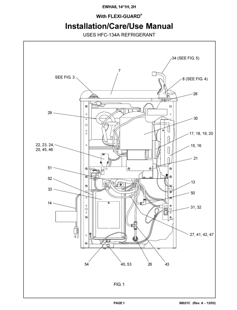
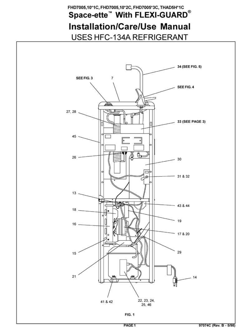
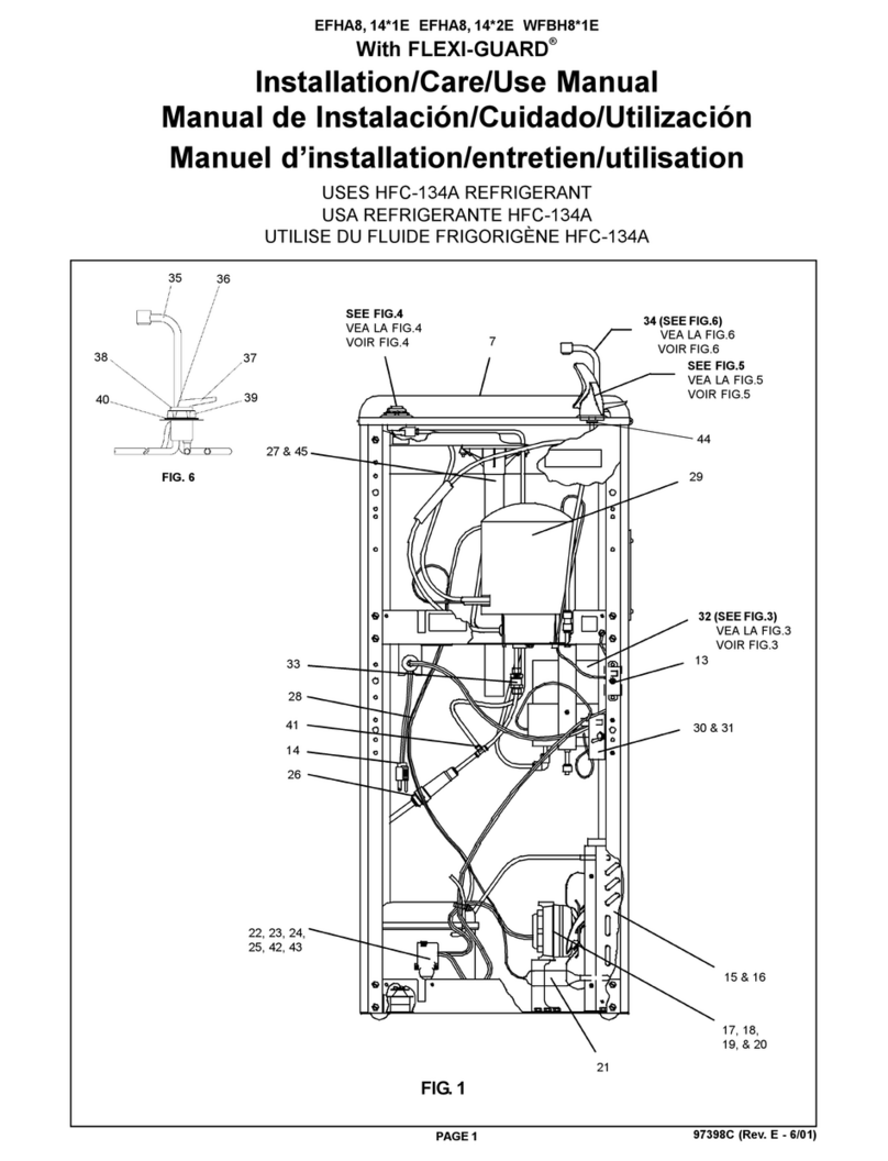
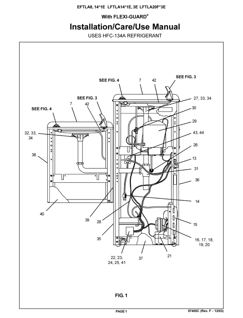
Drinking Fountain Doctor EHOA8 1G Instruction and safety manual

98061C (Rev. A - 8/05)
EHOA8*1G EHOA8*2GJO
PAGE 1
With FLEXI-GUARD®
Installation/Care/Use Manual
USES HFC-134A REFRIGERANT
FIG. 1
51
34
42
52
39, 40, 41
50
26
51
25
53
21
53
35, 36, 37
48
20
18
33
22, 23, 24
38
49
54
SEE FIG. 3
43, 44,
45
46
56
55
19
27,47
SEE FIG. 4
98061C (Rev. A - 8/05)
EHOA8*1G EHOA8*2GJO
PAGE 2
FIG. 2
FINISHED FLOOR
PISOACABADO
PLANCHERFINI
E = INSURE PROPER VENTILATION BY MAINTAINING 6" (152mm) (MIN.) CLEARANCE FROM CABINET LOUVERS TO WALL.
ASEGUREUNAVENTILACIÓNADECUADAMANTENIENDO UNESPACIO E 6" (152mm)(MÍN.) DE HOLGURAENTRE LA
REJILLADE VENTILACIÓN DELMUEBLEYLAPARED
ASSUREZ-VOUSUNE BONNE VENTILATION EN GARDANT6"(152mm) (MIN.) ENTRELES ÉVENTS DE L’ENCEINTE ETLE
MUR
F = POWER CORD 1-1/2FEET (457mm) LONG
CABLEELÉCTRICODE1½ PIE, 457 mm DELARGO
CORDOND’ALIMENTATION 1-1/2' (457mm)
G = THIS BOLT HOLE MUST BE USED FOR FASTENING UNIT TO WALL.
ESTEAGUJERO DE TUERCADEBERÁ SERUSADO PARAASEGURARLAUNIDADALAPARED.
ONDOITUTILISER CE TROU DEBOULON POUR INSTALLER L’APPAREILAU MUR.
H = ORIFICE HEIGHT 1-1/4" (32mm) ABOVE RIM
ALTURADELORIFICIO1-1/4" (32mm) SOBRE LACORONA
HAUTEURDE L'ORIFICE 1-1/4"(32mm) AUDESSUS DUREBORD
LEGEND/LEYENDA/LÉGENDE
A= RECOMMENDED WATER SUPPLY LOCATION 3/8 O.D. UNPLATED COPPER TUBE CONNECT STUB 1-1/2 IN. (38mm) OUT
FROM WALL SHUT OFF BY OTHERS
SE RECOMIENDAUBICAR EL TUBO CORTO DE CONEXIÓN ALTUBO DE COBRE SIN CHAPAR DE 3/8" DE DIÁM. EXT.A1-1/2"
(38mm)FUERADELALLAVE DE PASOENLAPAREDCOLOCADAPORTERCEROS.
EMPLACEMENTRECOMMANDÉ D'ALIMENTATIONENEAU PAR TUBE ENCUIVRE NON PLAQUÉDE 3/8 PO. (9,5 mm)D.E.
CONNECTANTUNETUYAUTERIEDE 1-1/2 PO.(38mm) DEPUIS LE ROBINET D'ARRÊT FOURNI PAR D'AUTRES.
B = RECOMMENDED LOCATION FOR WASTE OUTLET 1-1/4” O.D. DRAIN
UBICACIÓN RECOMENDADAPARAEL DRENAJE DE SALIDADE AGUA, DE 1¼” DE DIÁMETRO.
EMPLACEMENTRECOMMANDÉ POUR LE DRAIN DED.E. 1-1/4" DESORTIE D’EAU.
C = 1-1/4 TRAP NOT FURNISHED**
PURGADORDE 1¼ NO PROPORCIONADO**
SIPHON1-1/4 NON FOURNI**
D = ELECTRICAL OUTLET LOCATION
UBICACIÓNDE LA TOMADE ELECTRICIDAD
EMPLACEMENTDE LA PRISEDE COURANT
98061C (Rev. A - 8/05)
EHOA8*1G EHOA8*2GJO
PAGE 3
SENSOR RANGE ADJUSTMENT: The electronic sensor used in this cooler is factory pre-set for a "visual" range of 36
inches (914 mm). If actual range varies greatly from this or a different setting is desired, follow the range adjustment
procedure below:
A. Remove front panel of cooler.
B. Using a small tip screwdriver, rotate range adjustment screw clockwise to increase range and counterclockwise to
decrease range (See Fig. 3).
CAUTION: Complete range of sensor (24-46 inches/610-1168mm) is only one turn of the adjusting screw.
C. Replace front panel.
SENSOR CONTROL: If sensor fails to operate valve mechanism or operates erratically, check the following.
A. Ensure there are no obstructions within a 40 inch (1016mm) radius in front of cooler.
B. Check wire connections at the solenoid valve and sensor. CAUTION: Make sure unit is unplugged before checking any
wiring.
C. Ensure proper operation of solenoid valve. If there is an audible clicking sound yet no water flows, look for an obstruction
in the valve itself or elsewhere in the water supply line.
13
14
10
6
FIG. 3
HANGERBRACKETS &TRAP
INSTALLATION
1) Remove hanger brackets fastened to back of cooler by
removing one (1) screw.
2) Mount the hanger brackets and trap as shown in Figure 2.
NOTE: Hanger Brackets MUST be supported securely. Add
fixture support carrier if wall will not provide adequate
support.
IMPORTANT:
yAnchor hanger securely to wall using all six (6) 1/4 in. dia.
mounting holes.
3) Install straight valve for 3/8" O.D. unplated copper tube.
INSTALLATION OF COOLER
4) Hang the cooler on the hanger brackets. Be certain the
hanger brackets are engaged properly in the slots on the
cooler back as shown in Figure 2.
5) Loosen the two (2) screws holding the lower front panel at
the bottom of cooler base. Remove the front panel and
set aside.
6) Connect water inlet line--See Note 4 of General Instruc-
tions.
7) Remove the slip nut and gasket from the trap and install
them on the cooler waste line making sure that the end of
the waste line fits into the trap. Assemble the slip nut and
gasket to the trap and tighten securely.
START UP
Also See General Instructions
8) Stream height is factory set at 35 PSI. If supply
pressure varies greatly from this, adjust screw, ac-
cessibleby removing front panel(Item 7, Fig. 3). CW
adjustment will raise stream and CCW adjustment
willlower stream. Forbest adjustment,stream should
hit basin approximately 6-1/2” (165mm) from bub-
bler.
9) Replace the front panel and secure by retightening
two (2) screws.
ITEM NO. PART NO.
Panel-BottomDispenser
Bracket-ValveMounting
Sensor-Clear(115V & 230V)
SolenoidValve (115V)
Solenoid Valve (230V)
Panel-Right Side
Panel-Left Side
Panel-Front
Elbow 1/4 Stem x 1/4 O.D.
Fitting 1/4 NPTF x 1/4 O.D.
Nut-Regulator
Screw-#6-32 x 1/2" Lg. PHMS
Screw-#10 x 1/2" Lg. PHSM
Hex Nut
Screw-#8 x 5/8" Lg. Torx/Slot
Holder-Regulator
Regulator
Screw-#10 x 1/2" Lg. HHSM
26588C
26866C
36028C
31272C
35784C
See Color Table
See Color Table
See Color Table
70817C
75507C
56082C
70644C
75497C
40045C
70864C
50986C
61314C
70002C
Item No. 5
Part No.
COLOR TABLE
Gray Beige
Almond
Stainless Stl
Sandalwood
Granite
Light Gray
26635C
26636C
26637C
26638C
26641C
26642C
26605C
26606C
26607C
26608C
26611C
26612C
26731C
26732C
26733C
26734C
26737C
26738C
PANEL
COLOR Item No. 6
Part No. Item No. 7
Part No.
11 2
9
4
12 1
1
2
3
4
5
6
7
8
9
10
11
12
13
14
15
16
17
DESCRIPTION
NOTE: WATER FLOW DIRECTON
RANGE ADJUSTMENT SCREW
316
15
14
7
14
5
917
8
98061C (Rev. A - 8/05)
EHOA8*1G EHOA8*2GJO
PAGE 4
PRINTED IN U.S.A.
PARTS LIST 115V
ITEM NO. PART NO.
18
19
20
21
22
23
24
25
26
27
28
29
30
31
32
33
34
35
36
37
38*
39
40
41
42
43
44
45
46
47
48
49
50
51
52
53
54
55
56
Item No. 19
Part No.
COLORTABLE
Gray Beige
Almond
Stainless Steel
Sandalwood
Granite
Light Gray Beige
22706C
22707C
22708C
22709C
22711C
22712C
Frame - Back/Bottom
Wrapper
PowerCord
Fan Bracket
Fan Blade
Hex Nut - Fan Blade
FanMotor 115V
Screw - Fan Motor
Shroud - Fan
Clip (Front and Rear Panels)
Bubbler Assembly
Orifice Assembly
Pedestal
Housing Assembly
Locknut
Condenser
Drier
Grommet - Compressor Mtg.
Hair Pin - Cotter
Washer
Compressor Serv. Pak EMI 70 HNR
Overload
Cover - Relay
Relay
Heat Exchanger
Tailpipe
Strainer Assy
Gasket - Tailpipe
Basin
Screw - Basin Mtg.
Cold Control
Evaporator Assy
Strainer
Angle - Bracket Corner
Bracket - Front Support
Bracket - Basin Mtg.
Poly Tubing (Cut To Length)
Bracket - Hanger
Bracket - Hanger
27097C
See Color Table
36208C
27095C
30664C
70018C
31490C
70009C
56237C
70142C
56073C
40322C
55997C
56011C
75580C
66743C
66703C
50144C
70184C
70150C
36094C
36158C
35768C
35959C
66576C
40572C
40575C
50074C
21222C
75536C
31513C
66534C
55996C
27093C
27094C
27096C
56092C
20430C
20774C
WRAPPER
COLOR
DESCRIPTION
*INCLUDES RELAY & OVERLOAD. IF UNDER WARRANTY, REPLACE
WITH SAME COMPRESSOR USED IN ORIGINAL ASSEMBLY.
NOTE: All correspondence pertaining to any of the above water coolers or
orders for repair parts MUST include Model No. and Serial No. of cooler,
name and part number of replacement part.
WIRING DIAGRAM
This Drawing is merely for illustrating the
components of the electrical system.
NOTE:
WHEN INSTALLING REPLACEMENT
BUBBLER AND PEDESTAL, TIGHTEN
NUT (ITEM 32) ONLY TO HOLD
PARTS SNUG IN POSITION.
DO NOT OVER TIGHTEN.
BASIN
29
30
31
32
28
FIG. 4
PARTSLIST 220V
DESCRIPTION
ITEMNO. PARTNO.
20
24
38*
39
40
41
42
-
35987C
31430C
36085C
36195C
35768C
36050C
66552C
35826C
PowerCord
FanMotor
Compressor Serv. Pak EM65
Overload
Cover - Relay
Relay
Heat Exchanger
Power - Inlet
www.DrinkingFountainDoctor.com 800-518-5388

This manual suits for next models

1

Other Drinking Fountain Doctor Water Filtration System manuals
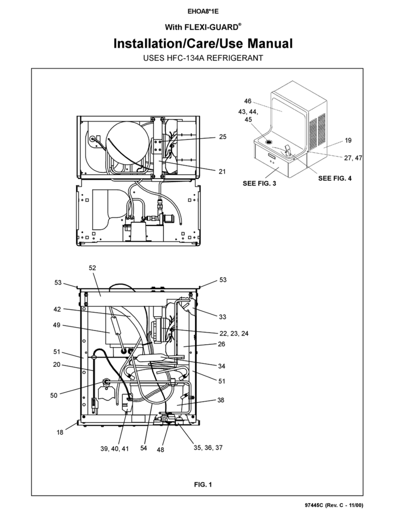
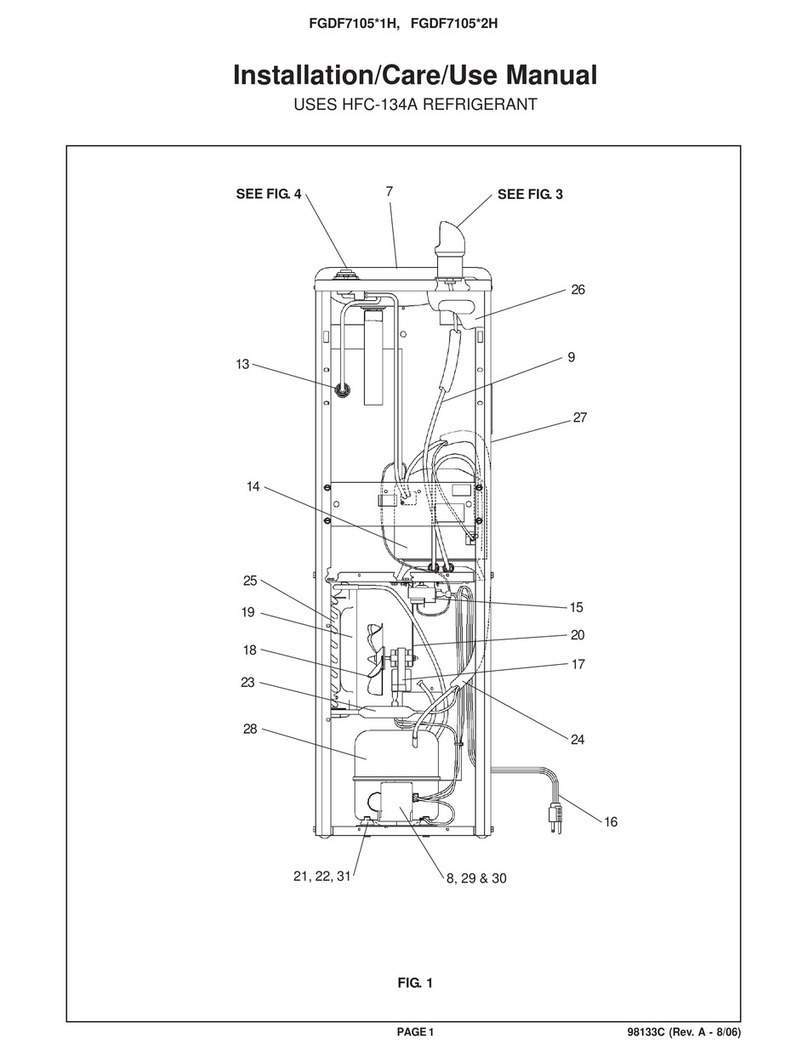
Drinking Fountain Doctor FGDF7105 1H Instruction and safety manual

Drinking Fountain Doctor

Drinking Fountain Doctor FGDF7105 1H Instruction and safety manual

Drinking Fountain Doctor Space-ette FHD700 5 1G Instruction and safety manual

Drinking Fountain Doctor

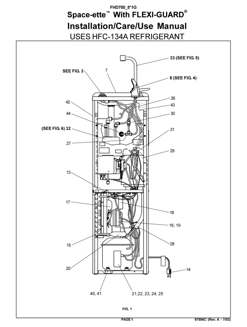
Drinking Fountain Doctor Space-ette FHD700 5 1G Instruction and safety manual

Drinking Fountain Doctor Space-ette FHD7005 10 1C Instruction and safety manual

Drinking Fountain Doctor

Drinking Fountain Doctor Space-ette FHD7005 10 1C Instruction and safety manual

Drinking Fountain Doctor EFHFA8 2 Instruction and safety manual

Drinking Fountain Doctor

Drinking Fountain Doctor EFHFA8 2 Instruction and safety manual

Drinking Fountain Doctor EWHA8 1C Instruction and safety manual

Drinking Fountain Doctor

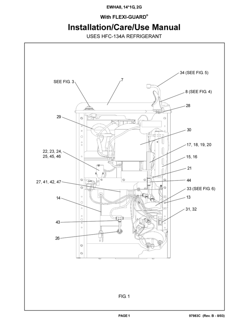
Drinking Fountain Doctor EWHA8 1C Instruction and safety manual

Drinking Fountain Doctor EFTLA8 1E Instruction and safety manual

Drinking Fountain Doctor

Drinking Fountain Doctor EFTLA8 1E Instruction and safety manual

Drinking Fountain Doctor EWHA8 1H Instruction and safety manual

Drinking Fountain Doctor

Drinking Fountain Doctor EWHA8 1H Instruction and safety manual

Drinking Fountain Doctor EWHA8 1G Instruction and safety manual
Drinking Fountain Doctor

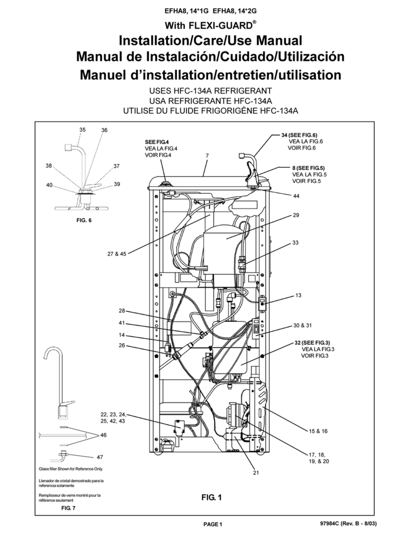
Drinking Fountain Doctor EWHA8 1G Instruction and safety manual

Drinking Fountain Doctor EHOA8*1E Instruction and safety manual

Drinking Fountain Doctor

Drinking Fountain Doctor EHOA8*1E Instruction and safety manual

Drinking Fountain Doctor EFHA8 1E Instruction and safety manual

Drinking Fountain Doctor

Drinking Fountain Doctor EFHA8 1E Instruction and safety manual

Drinking Fountain Doctor EFHA8 1G Instruction and safety manual

Drinking Fountain Doctor

Drinking Fountain Doctor EFHA8 1G Instruction and safety manual
Popular Water Filtration System manuals by other brands

Sera multi fil 350 manual

Sera

Sera multi fil 350 manual

LAMA Mini One user guide

LAMA

LAMA Mini One user guide

Aqua Free Germlyser G Instructions for use

Aqua Free

Aqua Free Germlyser G Instructions for use

Brita SAFF-100 user guide

Brita

Brita SAFF-100 user guide

Kohler KT001-MF installation guide

Kohler

Kohler KT001-MF installation guide

Metro Water Filter of the South 5600 Servicing instructions

Metro Water Filter of the South

Metro Water Filter of the South 5600 Servicing instructions

Watts Premier 500029 Installation, operation and maintenance manual

Watts Premier

Watts Premier 500029 Installation, operation and maintenance manual

Reflex Exvoid A 60.3 operating manual

Reflex

Reflex Exvoid A 60.3 operating manual

Hayward AquaRite 100 Technical Training Guide

Hayward

Hayward AquaRite 100 Technical Training Guide

A.J.Antunes UF-224 Series owner's manual

A.J.Antunes

A.J.Antunes UF-224 Series owner's manual

Kohler Aquifer Refine K-21371 Homeowner's guide

Kohler

Kohler Aquifer Refine K-21371 Homeowner's guide

Midea MU136-4 instruction manual

Midea

Midea MU136-4 instruction manual

Spirotech SPIROTRAP Magnet Installing and operating instructions

Spirotech

Spirotech SPIROTRAP Magnet Installing and operating instructions

Blake Water Solutions Specialist Series Operation and instruction manual

Blake Water Solutions

Blake Water Solutions Specialist Series Operation and instruction manual

Wallace & Tiernan SERIES V-2000 manual

Wallace & Tiernan

Wallace & Tiernan SERIES V-2000 manual

DriSteem 201 Installation, operation and maintenance manual

DriSteem

DriSteem 201 Installation, operation and maintenance manual

Automated Pure Water 400 Installation & operation

Automated Pure Water

Automated Pure Water 400 Installation & operation

amiad Omega 13.5K Installation & operation manual

amiad

amiad Omega 13.5K Installation & operation manual

manuals.online logo
manuals.online logoBrands
  • About & Mission
  • Contact us
  • Privacy Policy
  • Terms and Conditions

Copyright 2025 Manuals.Online. All Rights Reserved.