Drivecon PWR III Series User manual

OPERATION & INSTALLATION
MANUAL
PWR Series III
PUSHBUTTON TRANSMITTERS

1
I N DEX
PAGE.
1.
-
DEC
LARATION OF CONFORMITY……………...……………………………………..………….1
2.- SYSTEM DESCRIPTION………………...….…..……………………………………….…………..2
3.
-
SAFETY INSTRUCTIONS………………………..…………………………………….…….………3
3.1.- WHAT YOU MUST DO…………………………..………………………………………………...3
3.2.- WHAT YOU MUST NOT DO……………………..………………………………………………..3
4.- INSTALLATION…………………………………… …………………………………….………….4
4.1.- THE CB60 BATTERY CHARGER……………… ..………………………………….…………..4
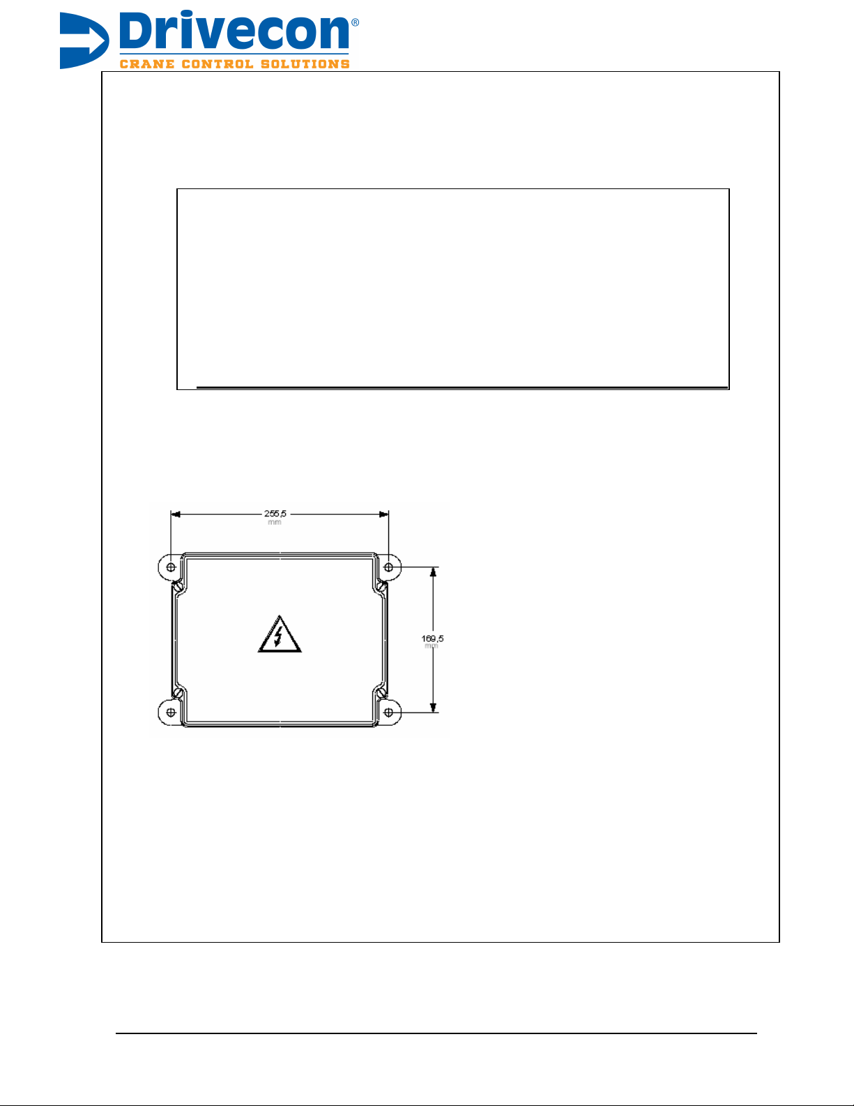
4.2.- RECEIVER…………………………………………..……………………………………...………5
4.3.- STARTING UP ………………………………………..………………………………………… .7
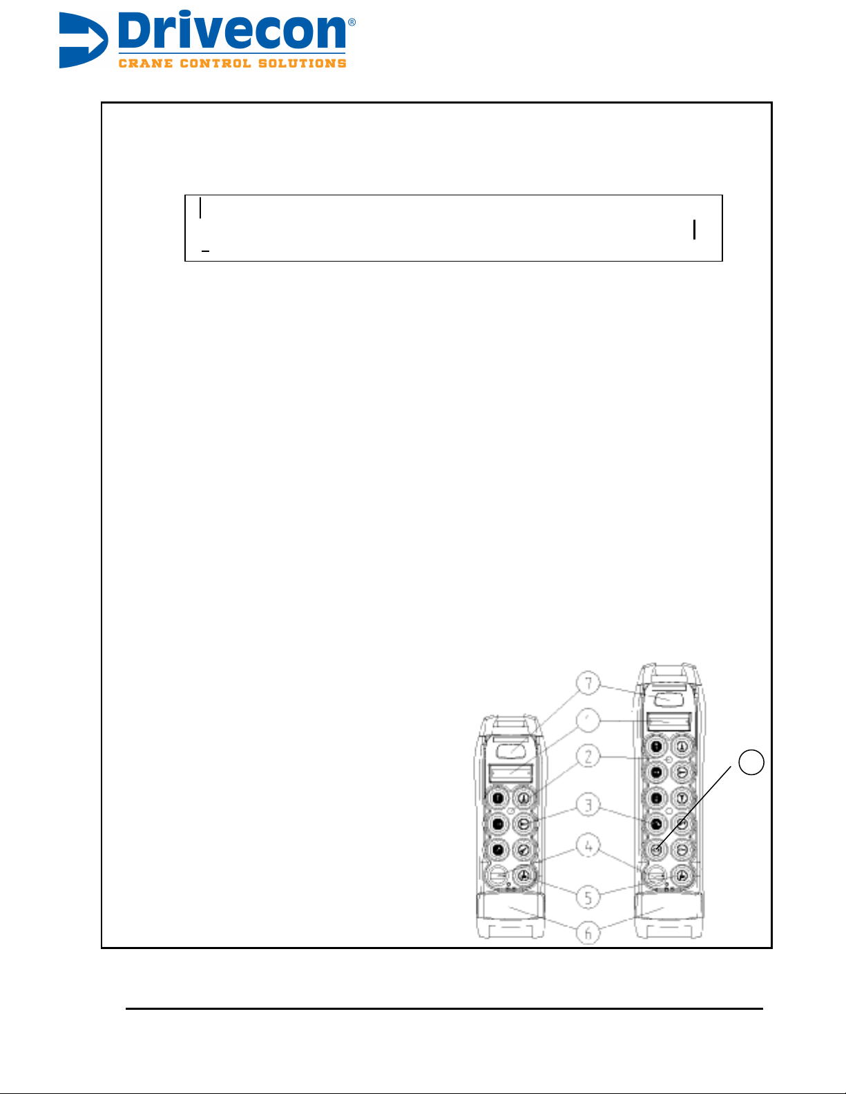
5.- USING THE RADIO..…………………………………. ….…………………………………………9
6.
-
TANDEM OPERATION………….………………………..……………………………………......10
6.1 - INTRODUCTION...............................................................................................................10
6.2 - SYSTEMS WITH 1 MASTER TRANSMITTER..................................................................11
6.3 - SYSTEMS WITH 2 MASTER TRANSMTTERS................................................................12
7.- FIRST COME - FIRST SERVED OPERATION......................................................................13
7.1 - INTRODUCTION................................................................................................................13
7.2 - SYSTEMS WITH 2 TRANSMITTERS................................................................................14
8.- PITCH & CATCH OPERATION.............................................................................................15
8.1 - INTRODUCTION.................................... ..........................................................................15
8.2 - SYSTEMS WITH 2 TRANSMITTERS................................................................................16
9.- RANGE LIMITER OPERATION.............................................................................................17
9.1 SYSTEM DESCRIPTION....................................................................................................17
9.2 - INFRARED SENSOR..........................................................................................................17
9.3 - INFRARED TRANSMITTER ............................................................................................19
9.4 - INSTALLATION...................................................................................................................20
9.5 - TECHNICAL CHARACTERICS OF THE LA70...................................................................21
10.- MAINTENANCE.....................................................................................................................22
10.1 -PRECAUTIONS.................................................................................................................22
10.2 -FAULT FINDING............................................... ................................................................22
APPENDIX A - PROGRAMMING A SPARE TRANSMITTER…………………………………...24
APPENDIX B
-
STANDARD WIRING DIAGRAMS....
.................................................................25

1
DECLARATION OF CONFORMITY
DECLARACION DE CONFORMIDAD
DECLARATION OF CONFORMITY
KONFORMITÄTSERKLÄRUNG
DECLARATION DE CONFORMITE
DICHIARAZIONE DI CONFORMITA'
DECLARAÇAO DE CONFORMIDADE
El Fabricante
The Manufacturer
Der Hersteller
Le Fabricant
Il Fabbricante
O Fabricante
ANGEL IGLESIAS, S.A.
Pol. Ind. 27, nº 30 20014
SAN SEBASTIAN - SPAIN
NIF: A-20-036.018
Tel : (+34) 943 448800
Fax: (+34) 943 448816
TM70/1
TM70/2
Declara que el producto: Telemando IKUSI
Declares that the product: Remote Control IKUSI
Erklärt, dass das Produkt: Funkfernsteuerung IKUSI
Déclare que le produit: Télécommande IKUSI
Dichiara che il prodotto: Radiocomando IKUSI
Declara que o produto: Radiocomando IKUSI
93/44 EC
99/5 EC
Cumple con las Directivas de Consejo:
Complies with the provisions of Council:
Erfüllt die Richtlinien des Rates:
Accompli les Directives du Conseil:
E´conforme alle Direttive del Consiglio:
Cumpre as Directivas del Consello:
Normas armonizadas utilizadas:
Applied harmonized standards:
Angewendete harmonisierte Normen:
Normes harmonisées utilisées:
Norme armonizate utilizzate:
Normas armonizadas utilizadas:
EN 61000-3-2
EN 61000-3-3
EN 60950-1
EN 50178
EN 60204-32
EN 60529
PrEN 13557
PrEN 12077-1
ETSI EN 300220
ETS EN 301489-3
EN 55022
EN 61000-4-2
EN 61000-4-3
EN 61000-4-4
EN 61000-4-5
EN 61000-4-6
EN 61000-4-11

2
2.
-
SYSTEM DESCRIPTION
The PWRSIII6 and PWRSIII10 push-button transmitter type, radio remote control
Systems are designed for the remote control of hoists and cranes, and are
particularly suitable for applications when the operator needs to be able to choose
the best location from which to carry out an operation.
The system consists of a transmitter for selecting commands and a receiver, which is
connected to the electrical system of the machine to be operated. The system also
comes with a battery charger and two rechargeable batteries.
The main specifications are as follows:
The PWRSIII
Frequency band 902.0 to 928.0 MHz; ERP <1mW
Response Time 100 ms
Temperature range -4ºF to +149ºF (-20º to +65ºC)
The PWRSIII6 and PWRSIII10 Transmitters
Protection
IP65
The Receivers
Power supply
115 Vac ± 10%, 50/60 Hz
Optional 48, 230 Vac ± 10%, 50/60 Hz
12 or 24 Vdc
Consumption
20 W
Relays
230 Vac/8 A
STOP Relays
230 Vac/6 A
Protection
IP55
Electrical Security Class II (EN50178)
The CB60 battery charger
Power supply
115 Vac ± 10%, 60Hz;
optional 230 Vac, 50/60 Hz; 24 Vdc; 12 Vdc
The BT06K batteries
Voltage
4.8 V
Capacity
750 mAh NiMH
Charging temperature 32º to 113ºF (0º to 45ºC)
Discharge temperature -4º to 122ºF (-20º to 50ºC)
Autonomy
10 h (operating at 50%)

3
3.
-
SAFETY INSTRUCTIONS
These instructions
must
be read carefully in order to install and
use the set properly and to keep it in perfect working condition
and to reduce the risks of misuse.
Do not use this set on machines for the lifting of persons or in
potentially explosive atmospheres.
Any use other than that specified in this manual is
danger
ous.
The following instructions must be strictly adhered to.
Strictly adhere to the instructions for installation contained in this manual
3.1.
-
WHAT YOU MUST DO
_
Make sure that professional and competent personnel carry out the installation.
Ensure that all site and prevailing safety regulations are fully respected.
Make sure that this manual is permanently available to the operator and
maintenance personnel.
Keep the transmitter out of reach of unauthorized personnel.
Remove the transmission key when the set is not in use.
On starting each working day, check to make sure that the STOP button and
other safety measures are working.
When in doubt, press the STOP button.
Whenever several sets have been installed, make sure the transmitter you are
going to use is the right one. Identify the machine controlled on the label for
this purpose on the transmitter.
Service the equipment periodically.
When carrying out repairs, only use spare parts supplied by Drivecon, Inc.
3.2.
-
WHAT YOU MUST NOT D
O
Never
make
any
changes
to
the
set
that
have
not
been
approved
by
manufacturer.
Never power the equipment with power supply other than specified.
Never allow unqualified personnel to operate the equipment.
After use, never leave the equip
ment ON. Always use the contact key or the
STOP button to avoid accidentally activating motion commands.
Do not use the set when visibility is limited.
Avoid knocking or dropping the set.
Do not use the set if failure is detected.

4
4.
-
INSTALLATION
4.1.
-
THE CB60 BATTERY CH
ARGER
The
battery
charger
CB60
has
two
charging
compartments
that
can
simultaneously charge battery types BT06, BT12, BT06K and BT08K.
Connect
the
charger
to
the
mains
using
the
power
source
and
cable
supplied.
On
installing
the
battery
charger,
bear
in
mind
that
the
batteries
must
be
charged
at
temperatures over 32ºF (0ºC)
and
that the power supply must be left on
all night. Also remember
that the
charger must not be left
in direct
sunlight,
as
t
he
batteries
will
Place the batteries in the charger. The
LED’s should light up, indicating that recharging is in process. Complete
recharging takes 12 hours, but the batteries may remain in the charger for an
unlimited period of time.
The capacity of the batteries decreases with use. Their life span is estimated to
be 500 recharging cycles, but this depends largely on the conditions of use, for
which the following is recommended:
Do
not
recharge
the
battery
until
it
is
completely
discharged.`
The
transmitter indicates this.
Always charge the batteries at temperatures between 32ºF and 113ºF (0º
and 45ºC).
Charge the batteries at least once every six months.
Avoid s
hort-circuits between the battery contacts. Do not carry charged
batteries in toolboxes or next to other metal objects (keys, coins, etc.).
Always keep contacts clean.
Never leave batteries in direct sunlight.
Only use Drivecon supplied batteries.
When the batteries are exhausted they can be disposed of or
recycled safely according to local standards.

5
4.2.
-
RECEIVER
assembly process,
keep
the work area free
and wear
Make sure that the crane is stopped for the entire duration of
the
protective clothing.
Park the crane and position stop-ends (if these are not
available use appropriate signs) at a suitable distance so that
other cranes on the same runway do not hit it.
Check the power-supply voltage and turn off the mains switch.
Remember that the receiver has several voltage-powered
circuits. Even when the power has been cut off, there is still a
risk of electrical shocks.
Find a suitable location for the receiver with easy access, in a place designated
for reception of the radio transmitter signal, and away from any intense radio
electric disturbance sources.
Install the receiver cabinet using 4 elastic absorbers.

6
indicates
the
correspondence
between
the
transmitter
commands
and
the
Connect the power supply and the receiver outputs on the corresponding relay board plug-
in terminals. Do this following the outputs diagram, which is supplied with the set. This
diagram
receiver outputs.
The STOP relays KSTOP1 and KSTOP2 are in series and must be connected
to the main contactor coil circuit.
The K2/START and K12 relays are activated when the start-up command is
held down.
Remember to connect the ground cable.
Only use fireproof cables for connections.
Select the appropriate voltage on the receiver, (230, 115 or 48 Vac)

7
4.3.
-
STARTING UP
which
may
lead
to
un
foreseeable
movements
on
Proceed with caution; the equipment may not be connected
correctly
s
tarting
-
up.
ON, indicates that the power supply is correct.
Once the receiver has been connected, disconnect the power supply to the
motors, (for example, by removing the fuses) and power on the receiver. With
this, the receiver will enter into a ‘SCANNING’ mode and the following LED’s
will be lit in the receiver;
POWER:
HARDOK:
ON, indicates the absence of faults on the boards.
SIGNAL:
OFF, in the case of the channels being signal free. Blinks ON
when there is a RF signal on the channels.
DATA:
OFF, when there is not another TM70 system active in the
area. Blinks ON in the opposite case.
ID:
OFF
Place a charged battery in the transmitter.
Next, turn transmitter ON to OPERATION mode, as follows:
_
Turn the contact key.
Push and pull out the STOP button, (LED flashes orange-green). If the
transmitter has LCD, it displays the identification of the machine, as well as
the battery level.
Press the start button. The green LED should now light indicating that the
transmitter is transmitting.
1.- Label identification.
2.- LED.
3.- Motion button.
4.- Contact key.
5.- Start button.
6.- STOP button.
7.- Range Limitation.
‘R’
R - Release

8
On receiving a signal from the transmitter, the receiver enters in OPERATION mode;
the following LED’s will light up on the receiver:
POWER: ON, indicates that the power supply is correct.
HARDOK: ON, indicates that defects have not been detected on the
board.
SIGNAL:
ON, indicates that it is receiving a RF signal at the working
frequency.
DATA:
When ON indicates that the data received has a correct
format.
ID:
When ON indicates that the receiver has recognized the
transmitter’s identification code.
Now,
the
STOP
r
elays
KSTOP1
and
KSTOP2
will
be
activated.
The
K2/START and K12 relays are activated when the start button is pushed in.
Press on any of the transmitter’s motion buttons and its corresponding relay
will be activated.
Check to make sure all the other movements work in this way.
Turn off the transmitter using the STOP button, and make sure that on doing
so the relays are deactivated and the DATA, ID and SIGNAL LED’s go out.
They behave exactly as in ‘SCANNING’ mode.
Reconnect the power supply to the motors, move to the usual work position
and check to see if all the motion and the stop button are functioning correctly.

9
5.
-
USING THE RADIO
To ensure correct use of the equipment, follow the instructions below:
Make sure the transmitter you are going to use is the right one, identifying the
machine on the identification label.
Attach the belt to the transmitter unit. Its use is recommended to prevent the
equipment from falling.
Insert a charged battery, turn the contact key and activate the transmitter.
To activate the system, you must first pull out the STOP button, the LED
should then give an orange-green pulse; then press the START button. If you
find that the STOP button has already been pulled out, it is necessary to push
it in and then pull it out again, as this sequence will allow the check in of the
STOP circuit. If the unit has experienced a time-out auto-disconnection, it is
not necessary to repeat the STOP button procedure, simply push the START
button for 1 second.
The green LED should light up, indicating that the transmitter has started
transmitting. From now on, if any of the transmitter’s command buttons are
pressed, the corresponding motion will be activated.
To be able to start up the transmitter, all the command controls associated with
active motion must be in the neutral position (not activated). This is not
the case for the selection functions.
When 4 minutes have passed and no active motion command has been
activated, the transmitter automatically goes to STAND BY mode, indicated by
green pulses each 3 seconds. To start it up once more, press the start button.
The transmitter is equipped with a circuit for monitoring the battery level. When
this level drops below a pre-established limit, the transmitter LED starts to
flash in red; 5 minutes later the transmitter switches off, and the machine’s
main contactor is deactivated. During this time, the load has to be located on a
safe position. If the STOP button is activated during this time, transmitter will
not start again, unless battery is replaced.
To switch off the transmitter, press the STOP button or turn off the contact key.
Remember that you are going to remote control a moving piece of
machinery. The safety instructions described in chapter 2 of this
manual must be strictly adhered to.

10
6.1 Series III – TANDEM OPERATION
6.1 Introduction
The tandem option allows operation of two cranes individually or in tandem by using one master transmitter.
There are two general types of tandem systems: Master/Master and Master/Slave. In Master/Master systems both
transmitters are capable of controlling any or both of the receivers/cranes at the same time. In Master/Slave systems
only the Master transmitter has the capability to do so, while the slave transmitter can only control its own
receiver/crane.
When starting the Master transmitter, you must first select 1+2 on the selector switch, pull up the E stop, and watch
the LED indicator.
Solid red LED means that the selector switch was not in the 1+2 position when pulling up on the E-stop.
Press the E-stop, select 1+2, and then pull up on the E-stop to continue.
A single flashing LED means that the selector switch needs to be changed to the position that the transmitter
was turned off in.
Double flashing LED means that the selector is in the correct position and the transmitter is ready to
communicate, press the start button.
.
Selection between receivers/crane can only be made if the slave or one of the master transmitters
(in Master/Master systems) first release their receiver/cranes, otherwise the access to the selected receiver or
receivers will be blocked for other transmitters, even in the case that the equipment is switched off. (Note: This does
not apply to First-Come-First-Serve systems.)
The cranes will only start when commanded to do so by the transmitter that most recently had control of that crane
unless it has been released. The release of the cranes to allow for another transmitter to obtain access to is
performed by selecting a different crane number (on a master transmitter configuration) and pressing and holding the
start button, or by pressing and holding the “R” button (on a slave transmitter configuration) and the start button
simultaneously.
Note: If the master transmitter does not power-up and its LED blinks in red at 0.4s interval rate or an
LCD equipped transmitters the display shows “Wrong Crane”, it is an indication that selection was
made with the transmitter switched off. The transmitter must then be switched off and restarted
with the selection switch in the position in which it was switched off.
Hint: Try all three positions
Tandem operation with cranes is always delicate.
Remember that there are safety devices (limit switches, anti collision guard systems,
etc.), which can affect operation and stop one of the cranes, while the other continues
working.

11
6.2.- SYSTEMS WITH ONE MASTER TRANSMITTER
RECEIVER 1
RECEIVER 2
F2
F1
F2
ID1
ID1
ID0
F1
F2
F2
ID1
ID0
SLAVE
MASTER
The master transmitter has a three position “1 / 1+2 / 2” selector switch, while the slave
transmitter has a release “R” pushbutton.
When a tandem operation is needed, operator of the master transmitter must require operator
of the slave transmitter to release the slave receiver/crane.The operator of the slave transmitter must
then start his crane and then depress “R” and “Start” pushbuttons simultaneously. The receiver will
then shut down and wait ready to accept transmission from any of the two transmitters. Next, operator
holding the master transmitter must then start his own crane, select the mode he wants to work in, “2”
to work with the slave crane or “1+2” to work in tandem with both cranes, and then press and hold
“Start” pushbutton until the requested receiver/crane powers up. Refer to the previous page for LED
indications
Once tandem or receiver/crane 2 mode operation from the master transmitter is complete,
operator must then select 1 on the master transmitter and press “start” to validate the
selection. The slave receiver/crane will then shut down and be ready for operation from the
slave transmitter.

12
6.3.
-
SYSTEMS WITH TWO MASTER TRANSMITTERS
RECEIVER 1
RECEIVER 2
F1
F2
F1
F2
ID0
ID1
ID1
ID0
F2
F1
F1
F2
ID0
ID1
MASTER II
MASTER I
In Master/Master systems both transmitters have a “1 / 1+2 / 2” selector and a release pushbutton
“R”.
When a tandem operation is needed, operator that is to have control of both receivers/cranes must
require operator of the other transmitter to release his receiver/crane.
I.e. If the operator of the Master I transmitter is to have control of both receivers/cranes, the operator
of the Master II transmitter must then start his crane and then depress “R” and “Start” pushbuttons
simultaneously. The receiver/crane 2 will then shut down and wait ready to accept transmission from
any of the two transmitters. Next, operator holding the master I transmitter must then start his own
crane, select the mode he wants to work in, “2” to work with the receiver/crane 2 or “1+2” to work in
tandem with both receivers/cranes, and then press and hold “Start” pushbutton until the requested
receiver/crane powers up. Refer to page 10 for LED indications
Once tandem or receiver/crane 2 mode operation from the master I transmitter is complete,
the operator must then release the receiver/crane or both receivers/cranes he wants to give up
control off. In order to do this, he must select 1, 2, or 1+2 on the master I transmitter and
press “start” to validate the selection. Once he has control of the receiver/crane or both
receivers/cranes he must then depress “R” and “Start” pushbuttons simultaneous. The
receiver/crane or both receivers/cranes will then shut down and be ready for operation from
the other transmitter.

1
3313
7. TM70 – FIRST COME – FIRST SERVED
OPERATION
7.1.- INTRODUCTION
This option allows the operation of one crane individually by using two transmitters with two
different ID codes, which determine which transmitter is governing the crane at a certain time.
For First come – First served applications the receiver is required to scan the radio channels
in order to receive radio signals from different transmitters.
The First come – First served mode is defined by EEPROM, and the transmitters do not need
to have a selector. The First come – First served mode consists of a receiver which liberates
the ID code every time the receiver is switched off, and hence it starts searching for IDs
defined in the EEPROM ID code list. The first valid ID code found is selected, and locked on
to it until the operator releases the crane by pressing the Stop button. After a time defined in
EEPROM (0.1 – 25 seconds, default 4 seconds), the receiver liberates the ID to which it was
locked and starts scanning IDs and radio channels. The first transmitter switched on is the
First transmitter to hold control of the crane, and it will not let any other transmitter to have
control of the crane until the transmitter is switched off.
A First Come – First Served operation with cranes is always delicate, given that the
receiver is FREE every time the STOP button is pressed or there is a radio link
failure.

7.2.
-
SYSTEMS
WITH TWO TRANSMITTERS
RECEIVER 1
F1
F2
ID1
ID2
F2
F1
ID2
ID1
TRANSMITTER 1
TRANSMITTER 2
Transmitters 1 and 2 have two different IDs and transmit in two different radio channels.
Once the receiver is switched off by any of the transmitters, after the liberation time defined
in the EEPROM, the receiver starts scanning for IDs and radio channels, looking for a
frame with the start order pressed.
A First come
– First served system can have up to 32 different transmitters governing a
single receiver.

15
8. TM70 – PITCH & CATCH OPERATION
8.1.
-
INTRODUCTION
This option allows the operation of one crane by two transmitters, through the selection of
ID codes, which determine the mode of operation. For this application, the SCAN option for
the receivers is required in order to receive transmitters in different channels.
This mode of operation consists of the use of a crane by two different transmitters. The first
transmitter governing the crane gets hold of the crane until it as switched off (in principle
exactly as the First come – First served mode of operation). In the event of pressing the
STOP pushbutton, the other transmitter is switched on and the START order is being
pressed, the second transmitter gets hold of the crane without falling the STOP relays. This
way, users of the same crane with different transmitters can pass each other the crane
without failing the STO
P relays. As the START pushbutton must be pressed when
transferring the crane, if the START relay has got a connected Horn, when the transfer is
done an audible sound can be produced.
Pitch & Catch operation is always delicate, given that the receiver
is FREE every
time the STOP button is pressed or there is a radio link failure.

16
8.2.
-
SYSTEMS WITH TWO TRANSMITTERS
RECEIVER 1
F1
F2
ID1
ID2
F2
F1
ID2
ID1
TRANSMITTER 1
TRANSMITTER 2
Transmitters do not need selectors. The receiver is the one that Frees its ID code.
When a Pitch & Catch operation needs to be performed, the user of the transmitter that wants to
Catch the crane must ask the user holding the crane to release the crane. The procedure is the
following: The owner of the crane must press the STOP button while the user that wants to Catch
the crane must be pressing the START button. The receiver will free the ID code and will SCAN
new ID codes and new channels, if in the lapse of time of a passive STOP, it encounters the new
ID it will keep on going without failing the STOP relays.
In the event that the transmitter governing the crane stops while the second transmitter is
switched off, the system will STOP normally and will be free until one transmitter with a valid ID
presses the START button.
When a Pitch & Catch operation is finished, the first transmitter to press START will get hold of
the crane.
This mode of operation is personalized in the remote control EEPROM and must be done by
DRIVECON personnel only

17
9. TM70 RANGE LIMITER
9.1.
-
SYSTEM DESCRIPTION
TM70 radio remote control systems can be equipped with a range limitation option for overhead
cranes, through which, the system is able to determine if the transmitter is located outside of a
zone, defined as a working area, and deactivates the controls when these situations arise.
coming
from
the
LA70
transmitter.
This
information
is
analysed
by
transmitter
The system consists of one or more Infrared transmitters LA70, installed either in fixed positions or
on the controlled crane, oriented in such a way that it covers the targeted working zone. In these
cases the transmitters of the remote control sets are equipped with a sensor which receives the
information
microprocessor,
which,
in
this
way
knows
when
the
operator
has
left
the
working
area.
Consequently, outputs are deactivated. Application examples
9.2.
-
INFRARED SENSOR
As explained in the above, the sensor element is located in the remote control transmitter and its
function is to receive the infrared information coming from the LA70 transmitter. The location of this
sensor is the following:

18
than
4
seconds,
all
the
active
commands
are
cancelled,
although
communication
is
The transmitter microprocessor receives the information from the sensor and checks the identity of
the crane. As soon as the sensor stops receiving the signal coming from the crane, the transmitter
LED, which was green, begins to flash in red, (in case of belly box transmitters, a buzzer also
sounds), in order to let the operator know that he has moved too far away. If this situation lasts
longer
maintained
with
the
receiver.
In
this
way
the
ma
in
contactor
and
the
selection
orders
are
maintained.
In order to return to the operating mode, all the worker has to do is move back into the working
zone. Movement orders must be disabled in order to restart movement. Once the transmitter enters
the working area, movement orders will not be ready to be used unless they have gone to zero.
This is to make movements start in first speed. If the remote control is provided with a Display,
whenever the transmitter is out of range, the message “Out o
f Range” will be displayed.
The remote control has got 4 modes of operation defined in the EEPROM:
1.- Range Limiter only at startup (Electronic Key): In order to make the transmitter work, it is
necessary that the transmitter is inside the starting zone, defined by the position of the infrared
transmitter.
2.- Range Limiter only in operation: The transmitter can be started anywhere, but the movement
orders will not work until the transmitter is inside the working zone.
3.- Range Limiter at startup and operation: The transmitter in order to work must be inside the
working zone always.
4.- Range Limiter only as an output Relay: This functionality makes the transmitter not to show In
range or Out of range situation in the transmitter itself. It will not mask any order. The information
will be sent to the receiver in order to process the information as an output relay or a condition to
the relay table.
Other manuals for PWR III Series
1
This manual suits for next models
2
Table of contents
Other Drivecon Transmitter manuals
Popular Transmitter manuals by other brands

BT Redcare
BT Redcare Essential installation guide

Vega
Vega VEGABAR 14 operating instructions

Akerstroms
Akerstroms REMOTUS MC8318 DRIVING INSTRUCTION

Emerson
Emerson Rosemount 5402 Reference manual

PCB
PCB EX1503M42 Installation and operating manual

Continental Automotive
Continental Automotive 451 TX user manual