Update 11/22/17
Page 2of 4
approximately 1/2”. You will hear and feel a distinct click, then lower the base which will separate from the body of the feeder. If you
are having difficulty removing the base, go to the “troubleshooting” section on page 3.
3. Use a 7/16” or 11mm socket, nut driver, or wrench to remove the nut on the bottom of the base, below the perch ring.
4. Remove the lock washer, hub, perch ring, and the green plastic friction disc. If you are having difficulty removing the hub, go to the
“troubleshooting” section on page 3.
5. Slowly pull the Power Stick upward to remove it from the base assembly. Keep in mind that there is a large spring inside the base
assembly directly underneath the Power Stick that may dislodge and fall out if the Power Stick is pulled out too quickly. If the switch
bumper separates from the base assembly when removing the Power Stick, it will be necessary to glue it back into place.
Replace the switch bumper on the base assembly if it is worn, indented, or punctured. If the damaged switch bumper is not replaced, the
activation switch on the Power Stick will not depress properly, causing dead spots at certain locations on the perch ring, the perch ring to spin
intermittently, or not spin at all. The top of the switch bumper can be inspected only after the removal of the Power Stick.
Switch Bumper Installation
Needle nose pliers and a utility knife may be used to remove the damaged switch bumper and the old
glue before installing the new switch bumper.
Apply a small amount of Super Glue®, Krazy Glue®, etc. on the edges of the slot. Before sliding the
switch bumper in place, make certain that it follows the curve of the base assembly. The top of the
switch bumper should be flush with the rim of the base assembly when installed correctly. Allow the
glue to dry completely before installing the Power Stick.
Base Assembly
Base - Reassembly & Installation
1. Hold the base assembly upright and position the spring inside the center cavity of the base assembly.
2. Align the switch bumper under the activation switch on the Power Stick and insert the Power Stick into the base assembly. Flip the
base assembly with the Power Stick upside down.
3. Install the friction disk, smooth side facing the bottom of the base assembly, and the perch ring, perch facing down, onto the drive shaft.
4. Align one of the four spokes on the perch ring with the flat side on the drive shaft, located directly beneath the threads.
5. Locate the flat side in the center of the hub, at the end of one of the four grooves in the hub. With the four grooves in the hub facing
downward, align the flat side in the center of the hub with the flat side on the drive shaft, and push down on the hub, locking it in place.
6. Install the lock washer, the nut, and tighten the nut by hand. Use a 7/16” or 11mm socket, nut driver, or wrench to finish tightening,
compressing the lock washer + 1/8 turn. The nut is installed correctly when the end of the drive shaft is flush or slightly higher than
the nut. Do not overtighten the nut as this may cause the drive shaft to break at the threads.
7. Install the base to the body of the feeder by placing the palm of your hand under the base, inserting your thumb and fingers upward
through the spokes of the perch ring. Grasp the base assembly and insert the three metal locking tabs into the three slots located
underneath the port and twist clockwise (viewed from the bottom), approximately 1/2”. You will hear and feel a distinct click. The
base is installed correctly when one of the three arrows ( ) on the underside of the base assembly is aligned with the right hash mark
on the side of the port.
Body - Disassembly
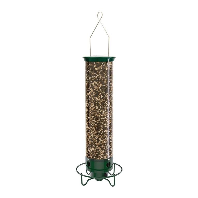
1. Release the tube from the port by removing the four tube screws.
2. Optional: The port and silo assembly may be disassembled for easy and thorough cleaning, by removing the three screws located
underneath the bottom of the port.
3. Lift the cap halfway up the bail wire which will allow the cap & bail wire assembly to fall to the side. Gently pull each end of the bail
wire out of the bail rod.
4. Lay the tube on its’ side with the bail rod parallel to the counter or floor. Using the palm of your hand, push down on the tube over the
bail rod until the tube becomes oval/oblong in shape. This will release the tube from the groove on one end of the bail rod. Reach inside
the tube and shimmy the other end out of the hole.
Body - Reassembly
1. Install the bail rod by inserting it into both of the designated holes in the top of the tube. Using the palms of your hands, apply pressure
to the outside of the tube at both ends of the bail rod, until the tube locks into each groove.
2. Replace the cap & bail wire assembly by inserting each end of the bail wire into the bail rod. Make certain each end is fully inserted
before sliding the cap back into place on top of the tube.
3. Assemble the port and silo assembly, if you chose to disassemble for easy, thorough cleaning, by placing the silo assembly inside the
port. Hold the silo assembly and port upside down and rotate the silo assembly until the three holes in the port line up with the three
plastic posts on the silo assembly. Replace the three screws.
4. Place your tube on the port aligning the holes in the tube with the holes in the port. Install each tube screw slowly, stopping as soon as
you feel slight resistance. Do not overtighten the screws as this will cause the tube to crack in hot weather from heat expansion,
or in cold weather from ice expansion. Cracking due to expansion, is not covered under our Lifetime Warranty against squirrel
damage.
