Drucker 642E User manual

Programmable
Run Time is Factory
Preset to
10
MINUTES
See Page 5
Replacement Parts:
Part No. Description
7724037 Foot, rubber
7751068 Switch, lid safety
7786061 Rotor, six-place, horizontal
7735049 Motor, 1/30 H.P., 115 V.A.C. permanent split capacitor
7729006 Capacitor, 4uF, 250V A.C.
7717051 Electronic timing and locking board
7751043 Circuit Breaker
7760002 Power cord
7714101 Pawl, latch, lid
7714103 Knob, latch, lid
7724071 Hinge, friction
7732018 Seal, lid gasket
7713031 Red Tube Holder, for 17 mm x 100 mm tubes
7713033 Green Tube Holder, for 17 mm x 75 mm Tubes
02-002-1-0011 Lid Assembly
03-0-0003-0068 Front Panel Label
Available Accessories:
Shield caps
p/n 7713011
1” Tube cushion
p/n 1525
Made in the USA by
0.5 to 1 mL
Tube Adapter
p/n 7713068
13 x 75 mm Insert
p/n 7713064
13 x 100 mm Insert
p/n 7713066
1.5 to 2 mL
Tube Adapter
p/n 7713065
200 Shady Lane, Suite 170 • Philipsburg, PA 16866
Phone: 814-342-6205 or 814-692-7661 • Fax: 814-692-7662 • www.druckerdiagnostics.com
WARRANTY:
The Drucker Diagnostics warranties that this centrifuge is free from
defects in workmanship and parts for 2 years.
0.25” Tube cushion
p/n 9150
SmartView™ Platform
p/n 00-179-009-001
Protected by U.S. Patents #6,811,531, & #D718463
Other Patents Pending
Operator’s Manual
Model 642E • Laboratory Centrifuge
Rev. I
P/N 03-0-0002-0039

Page 2
Model Description:
The Model 642E is a continuous-duty, electronically-controlled horizontal
centrifuge with a lid safety interlock system. The unit is controlled by an
electronic push–button timer that has been preset for ten (10) minutes, for
precise spin times and ease of use. Samples can be safely viewed through
the transparent lid. Entry into the machine is restricted during operation by the
safety interlock system. The Model 642E features a lighted control panel that
displays the status of the machine, easily viewable from a distance.
For warranty information, turn to page 12.
Intended Use:
General purpose laboratory centrifuge for sample separation.
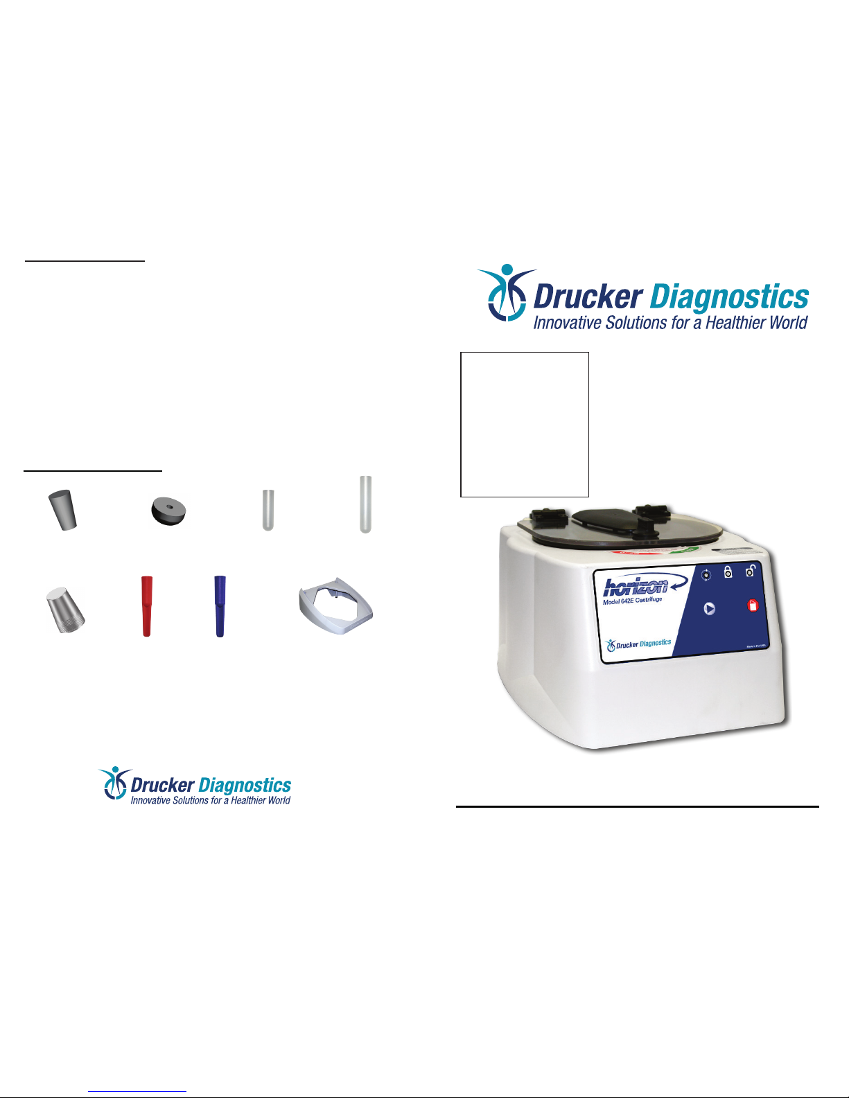
Supplied Equipment*:
The following items come standard with each Model 642E centrifuge:
1. One (1) six–place horizontal rotor
2. Six (6) 100 mm tube holders
3. Six (6) 75 mm tube holders
4. Two (2) 13 x 75 mm inserts p/n 7713064 (Not shown below)
5. Two (2) 13 x 100 mm inserts p/n 7713066 (Not shown below)
6. Two (2) 0.5 to 1 mL tube adapters p/n 7713068 (Not shown below)
7. Two (2) 1.5 to 2 mL tube adapters p/n 7713065 (Not shown below)
WARNING: For the safety of both the opera-
tor and service personnel, care should be
taken when using this centrifuge if handling
substances that are known to be toxic,
radioactive or contaminated with pathogenic
microorganisms. When Risk Group II ma-
terials are used, (as identied in the World
Health Organization “Laboratory Bio-Safety
Manual”), a Bio-Seal should be employed.
The Bio-Seal accessory for the model 642
tube holders is the non-aerosol shield cap,
p/n 7713011. In the event that materials of a
higher risk group are being used, more than
one level of protection must be provided.
The use of ammable or explosive materials
as well as those materials which have a
vigorous chemical reaction is prohibited.
For your safety and the durability of your
machine, never transport or store centrifuge
with tube holders inside machine.
Table of Contents
Model Description ............................... pg. 2
Intended Use....................................... pg. 2
Supplied Equipment ............................ pg. 2
Features .............................................. pg. 3
Specications ...................................... pg. 3
Setup Location .................................... pg. 3
Initial Setup Procedure........................ pg. 4
Front Panel Controls ........................... pg. 5
Operation ............................................ pg. 6
Tube Holder Congurations ................ pg. 7
Rotor Removal and Installation ........... pg. 8
Care and Maintenance........................ pg. 8
Cleaning and Disinfection ................... pg. 9
Troubleshooting................................... pg. 10
Safety .................................................. pg. 11
Emergency Rotor Chamber Entry ....... pg. 11
Calibration and Ground Testing........... pg. 11
Replacement Parts.............................. pg. 12
Available Accessories ......................... pg. 12
p/n 7786061
p/n 7713031
p/n 7713033
Page 11
1. 2.
x6
* The rotor and rotor accessories are rated for a rotation frequency of 4,000 RPM.
3.
x6
Safety:
Lid Safety Switch: The Model 642E lid is secured to the top of the cabinet by
a latching knob and pawl system. When the knob is rotated clockwise, the pawl
grips the underside of the cabinet opening and prevents the lid from opening.
A mechanical stop positions the pawl and prevents it from rotating completely.
When rotated to the stop position, the pawl makes contact with a micro–switch
mounted underneath the cabinet top. The lid safety switch prevents the centri-
fuge from operating while the lid is open. An indicator light on the front of the
machine will light up when the lid has been latched properly.
Lid Safety Interlock System: In addition to the Lid Safety Switch, the Model
642E has a true “0 RPM” lid locking system. The lid safety interlock system
keeps the lid locked at all times, (even during power failure), and requires that
the rotor be at rest in order to unlock the lid. The centrifuge will not allow entry
into the rotor chamber unless the centrifuge has power and the rotor is stopped.
To open the lid, make sure that the centrifuge is plugged in and, with the rotor
stopped, press the ‘OPEN / STOP’ button.
Note: After the centrifuge has started spinning, it may be possible to rotate
the lid knob enough to cause the pawl to lose contact with the lid safety
switch. If this happens, the centrifuge motor may lose power, but the lid
will still remain locked. If the knob is accidentally moved and this situation
should occur, rotate the knob fully clockwise to its stop position and the
centrifuge will resume operation.
Circuit Breaker: The Model 642E is protected with a 4 Amp circuit breaker lo-
cated at the rear of the machine mounted to the base. Any electrical short circuit
will cause the breaker to cut power to the machine.
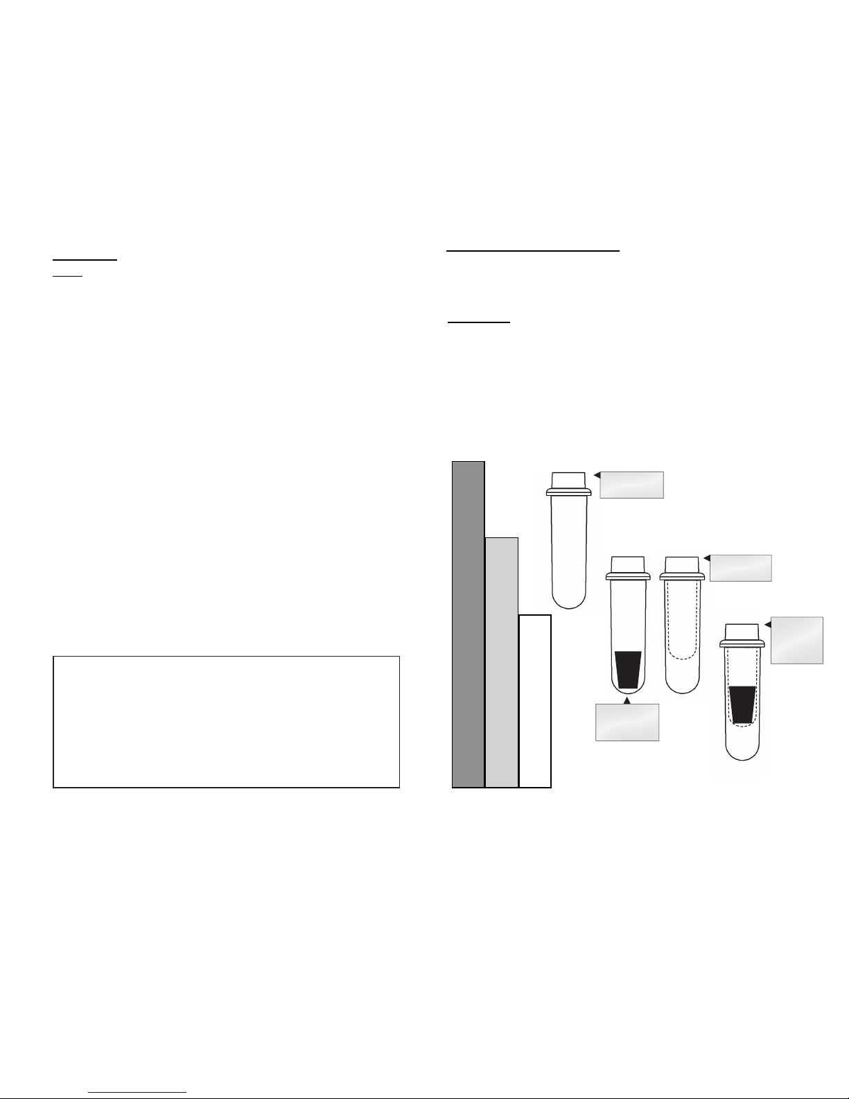
Emergency Rotor Chamber Entry:
In the event of power failure, it may be impossible to unlock the lid by
conventional means. In this case, entry into the rotor
chamber may be made by removing the latch label
and using a pen to manually disengage the locking
mechanism (see photo). Pull the mechanism towards
the control panel and then unlatch and open the lid.
If the unit is damaged, contact your authorized dealer
or Drucker Diagnostics.
Calibration and Earth Ground Testing:
It is recommended that the top speed, ground continuity and line leakage
be tested every two years for continued safe operation. Contact Drucker
Diagnostics for further information or testing availability.
For Optional Accessories see the last page of this manual
B
B
C
C
D
D
The Model 642E complies with US, Canadian, and European Safety standards.

Features:
• Swing–out horizontal rotor design, incorporating a unique test tube holder that
produces horizontally separated samples while requiring no additional parts
• Cool–Flow air ow design that prevents overheating of samples
• Heavy gauge steel construction for safety and durability
• Lid safety switch that prevents the centrifuge from operating unless the lid is
closed and latched
• Removable rotor for easy cleaning
• Locking lid that allows entry into the centrifuge only after the rotor has completely
stopped
• Brushless permanent split capacitor AC motor
• Clear lid for safe observation of samples and optical calibration of speed
• Electronically controlled timed operation, (see pg. 5)
• Push-button operation
• Indicator lights:
‘RUNNING’ Green –lights when power is applied to the motor
‘LATCHED’ Yellow –lights when the lid is closed and latched
‘UNLOCKED’ Red –lights when the lock system is deactivated
Page 3
Specications:
General Specications for the Model 642E Centrifuge
Nominal Speed (Horizontal): 3,380 (+/- 100) RPM
Nominal RCF (Horizontal): 1,600 (+/- 90) xg
Maximum capacity (Horizontal): 60 mL (6 x 10 mL)*
Overall Dimensions (H x W x D): 8.75 in. x 11.75 in. x 14 in.
Centrifuge Motor: 1/30 HP, p.s.c. motor
Maximum Acceleration Time: 10 seconds
Protection Breaker: 4 Amp. re–settable
Timer: electronic, 1 to 30 minutes
preset to 10 minutes, +/– 1%
Current Requirement: 1.9 Amps
Voltage Requirement: 115 (+/- 10) Volts
Frequency: 60 Hz
Weight: 11 lbs.
Any use other than those specied by the Manufacturer is explicitly prohibited.
* Maximum sample density is 1.15 grams / mL, (water density = 1.0 grams / mL)
Page 10
1. Problem: The rotor does not spin freely.
Solutions: – Make sure nothing has fallen into the rotor chamber.
– If there is nothing obstructing the rotor, the rotor may be damaged.
contact Drucker Diagnostics for further assistance.
2. Problem: Excessive noise when the machine is running.
Solutions: – Check to see that the load is balanced.
– Make sure that nothing has fallen into the rotor chamber.
– Make sure that the nut in the center of the rotor is tight.
– Have a technician test the motor and replace it if necessary.
3. Problem: The centrifuge does not run.
Solutions: – Check the electrical outlet.
– Make sure the lid latch is turned completely clockwise to its stop
position. When the lid is closed properly, the latch light on
the control panel will illuminate.
– Check the circuit breaker switch at the bottom left of the machine.
If the switch is white, the breaker has tripped. Contact Drucker
Diagnostics for further assistance.
– The printed circuit board may be damaged. Have a technician test
and replace the circuit board if necessary.
4. Problem: The latch light does not come on when the lid is closed.
Solutions: – Make sure that the unit has power.
– Make sure the lid latch is turned completely clockwise to its stop
position. The latch makes contact with a switch underneath the
front top of the cabinet. If this switch is not activated, the light will
not turn on and the machine will not run.
5. Problem: The machine does not unlock after a run has completed.
Solutions: – The lid should remained locked until the rotor has nearly come to a
complete stop and then unlock for 60 seconds. If additional unlock
time is needed, press the ’OPEN / STOP’ button with
the machine plugged in and the rotor stopped. If the lid remains
locked after this and will not unlock, the electronics may have been
damaged. Contact Drucker Diagnostics for assistance. To
access the rotor chamber, follow the procedure on page 11,
“Emergency Rotor Chamber Entry”.
6. Problem: The run time is not set to the desired length.
Solutions: – Check the run preset by following the instructions on page 5. If
the preset is not the desired length follow the procedure on the
same page to change the run preset time.
Troubleshooting:
NOTE:
The latch must be turned completely clockwise to its stop position in order
for the centrifuge to operate.
For servicing information or additional technical support, contact
Drucker Diagnostics at 814-342-6205 or 814-692-7661.
Setup Location:
1. Unpack the centrifuge and verify that all of the supplied equipment is present.
2. Choose a setup location which meets the following criteria:
a) A bench top clearance height of 20” is required in order to open the lid.
b) The clearance envelope is the space around the centrifuge which is
required for safety. Choose a setup location which will allow for a clearance
envelope of at least 24” x 24”, (with the centrifuge at the center). No person
or hazardous material shall be permitted in the clearance envelope during
operation. The operator time within the envelope shall be limited to the time
necessary for loading, unloading and centrifuge operation only.
c) Proper ventilation is necessary to prevent the overheating of samples as

well as premature failure of the centrifuge. Choose an area which will allow
unencumbered air ow.
d) The centrifuge is designed to secure to the operating surface by four suction
feet. No adjustment is necessary for leveling the centrifuge, however, the
surface should be at and level.
e) Be sure the outlet is always within reach as the line cord is the means of
emergency disconnection!
Initial Setup Procedure:
If any problems are found during the initial setup procedure, refer to the
troubleshooting section on page 10. For further assistance, contact
Drucker Diagnostics at 814-342-6205 or 814-692-7661.
1. Plug the centrifuge in to an approved electrical outlet. For electrical safety, the unit
must always be properly grounded.
2. For safety purposes, the locking system is always activated. To deactivate the
system, (in order to insert or retrieve samples), press the ‘OPEN / STOP’ button on
the control panel. The ‘UNLOCKED’ indicator light should illuminate. If it does not,
refer to page 10 on troubleshooting. The lid will be unlocked for 15 seconds after
pushing the ‘OPEN / STOP’ button.
3. Turn the latch counterclockwise and open the lid.
4. Spin the rotor by hand; check for free and level rotation. If the rotor does not spin
freely, refer to page 10 on troubleshooting.
5. Place the six test tube holders inside the rotor (as shown to the right), and verify
that they are seated properly.
6. Close the lid. Rotate the lid knob clockwise to its complete
stop position.The ’LATCHED’ indicator light should be
illuminated. If it is not, make sure that the lid is latched
properly. The centrifuge will not run unless the lid is latched
and that the ’LATCHED’ light is on.
7. Turn the centrifuge on by pushing the ‘START’ button.
8. The ‘RUNNING’ indicator light will illuminate.
9. The test tube holders will slide up into the horizontal position and the unit will
accelerate to full speed.
10. Listen to the sound of the centrifuge. A smooth whirring sound should be heard. If
there are any loud or unusual sounds, stop the centrifuge by pushing the ’OPEN /
STOP’ button immediately and refer to page 10 on troubleshooting.
11. While the machine is running, try to turn the latch counterclockwise. Power may
be cut to the motor but you should be unable to fully turn the latch. If it is possible
to turn the latch and open the lid while the unit is running, contact Drucker
Diagnostics for assistance. Close and latch the lid.
Page 4 (cont.) Page 9
Cleaning and Disinfection:
To prolong the life of the centrifuge cleaning and disinfection is recommended every
six months, or whenever there is a spillage or tube breakage. Contaminants must
be removed immediately, or corrosion and premature degradation of components
can occur.
1. Unplug the centrifuge before cleaning.
2. Apply cleaning solutions with a towel or cloth. Do not submerge the centrifuge
in water or other cleaning solutions as this will cause damage and void the
warranty.
3. ONLY isopropyl alcohol, soap and water, or a 10% (5500 PPM) bleach
solution should be used for cleaning and disinfection of the centrifuge and
accessories.
4. All surfaces must be dried immediately after cleaning and disinfecting.
5. TBQ Germicidal products shall not be used, as they will cause damage to the
centrifuge and void the warranty.
6. The use of fully/partially halogenated hydrocarbons, ketones, esters, ethers,
benzyls, ethyl benzenes, and all other chemicals not prescribed by the
manufacturer shall not be used as they may cause damage to the rotor
chamber, rotor, tube holders, accessories and centrifuge exterior and void the
warranty.
7. It may be necessary to remove the rotor and clean the rotor chamber. Follow the
instructions on page 8 to remove and reinstall the rotor.
12. Push the ‘OPEN / STOP’ button. The ‘RUNNING’ indicator light should
go out and the motor should slow to a stop.
13. The lid should remain locked until the rotor has nearly stopped. If
the machine unlocks prematurely, contact Drucker Diagnostics for
assistance.
Once the rotor has stopped, the interlock system will become
disengaged for sixty (60) seconds. The ‘UNLOCKED’ indicator light will
illuminate during this time.
14. To gain entry into the centrifuge after this period has ended, simply press
the ‘OPEN / STOP’ button. The lid will unlock for fteen (15) additional
seconds.
After the centrifuge has passed this procedure it is ready for operation.
glass fragments left in the tube holder after a tube breakage may adhere to
the next test tube inserted in that holder. When this tube is handled, these
fragments may puncture protective gloves and lacerate the operator’s
ngers or hand. Remaining fragments may provide stress points on
subsequent tubes and result in additional breakage. If a tube breakage
occurs, carefully remove the tube holder. Properly dispose of the sample
and tube fragments and thoroughly clean both the inside and outside of the
tube holder. Insert a new tube cushion (if necessary) and replace the tube
holder in the rotor.
4. Motor and Electrical Maintenance: The Model 642E uses a brushless
permanent split capacitor AC motor. It should not need servicing for the life
of the centrifuge. The electrical components are selected for high reliability
and should not need service.
5. Tube Holder Replacement: It is recommended that the tube holders be
replaced after 24 months of use. Inspect tube holders regularly for cracks. If
cracks are discovered, replace immediately.
6. Remove Accessories Before Moving: All tube holders, samples, and caps
must be removed from the rotor chamber before transporting or storing the
centrifuge to prevent damage and injury.

To verify the preset time: NOTE: Your centrifuge must be plugged in.
a. Push the OPEN / STOP button to disengage the lock and then
open the lid.
b. Push and hold the START button for approximately three (3) seconds. The Yellow
LATCHED indicator light will begin to ash, indicating program mode.
c. When you release the START button, the RUNNING indicator light will begin to
ash. Each ash represents one minute of run time.
d. Press the START button to verify the brake setting. When you release the START
button, the RUNNING indicator light will begin to ash. Each ash represents the
brake setting, from 1 to 10.
To change the preset time: NOTE: Your centrifuge must be plugged in.
a. Push the OPEN / STOP button to disengage the lock and then
open the lid.
b. Push and hold the START and OPEN buttons for approximately three (3)
seconds. The yellow LATCHED indicator light will begin to ash slowly, indicating
that you can now program run time.
Model 642E Centrifuge
03-0-0003-0068 642E Drucker Diagnostics
Revision: C
Tooling: LT-026
Material: 0.010”Polycarbonate
Finish:Velvet
Embossing Height: 0.010"
Adhesive: FLEXmount® DFV 400 F WHITE V-344 90 PFW
Note: Supplier must specify materials used on quotes & proof
Black White
Pantone 288 C
Pantone 3135 C
Pantone 485 C 200 Shady Lane,Suite 170
Philipsburg,PA 16866
(814) 342-6205 Fax: (814) 342-6211
www.druckerdiagnostics.com
Clear velvet finish
Page 5
‘RUNNING’ Lights up when the machine
is in operation, (power is
being applied to the motor).
‘LATCHED’ Lights up when the lid has
been closed and latched
properly.
‘UNLOCKED’ Lights up to indicate that the
locking mechanism has been
deactivated, allowing access
to the rotor chamber.
‘START’ Begins a new run, (the lid
must be closed, see pg. 6).
‘OPEN / STOP’Allows for access into the
rotor chamber by disengaging
the locking mechanism. Entry
is only permitted when the
rotor is stopped. Pressing this
button during operation will
terminate the run and unlock
the lid after the rotor has
come to a stop.
Page 8
(cont.)
c. Press START one time for each minute of run time desired, from a minimum of
1 minute to a maximum of 30 minutes. The green START indicator light will ash
each time you press the START button.
d. Press OPEN to enter the run time. You will now begin to adjust the brake setting.
e. Press START to adjust the brake setting, from a minimum of 1 to a maximum
of 10. The green START indicator light will ash each time you press the start button.
f. When you are nished, press the ‘OPEN’ button to exit. Use the above procedure
to verify the run time and brake setting change.
Rotor Removal and Installation:
To remove the rotor:
1. Unlock the centrifuge by pushing the ‘OPEN / STOP’ button and unlatch
and open the lid.
CAUTION: Unplug the centrifuge from the electrical outlet at this time to
eliminate the possibility of electrical shock or other injury.
2. Remove the test tube holders.
3. Remove the nut in the center of the rotor by turning it counterclockwise,
(a tool may be required).
4. The rotor is sitting on a cone-shaped adapter. Pull the rotor up and off of
this adapter.
To install the rotor:
1. Place the rotor back onto the cone-shaped adapter. You may need to turn
the rotor slightly to line it up properly.
2. The rotor should slide onto the rotor cone freely.
3. Once a proper t has been achieved, replace the nut and turn it until it is
hand-tight, (a tool may be required).
4. Replace the tube holders and verify that they are seated properly, (as
shown on page 4).
5. It is recommended that the initial setup procedures be performed to ensure
that the rotor has been installed correctly and that no damage has been
done to the centrifuge during either the rotor installation or possible rotor
chamber cleaning. See page 4 for this procedure.
Care and Preventative Maintenance:
With proper care and maintenance your centrifuge will provide years of laboratory
service. For proper care, the following steps should be taken:
1. Provide Adequate Ventilation: For cooling purposes, the Model 642E draws in
ambient air through the air intake cover on the top of the lid and exhausts
this air in the rear of the base. The centrifuge should be placed on a hard
smooth surface for good air circulation.
2. Always Spin Balanced Loads: Make certain that you are always spinning a
balanced load. The Model 642E has a unique counter balanced motor
mounting design which, along with it’s rubber suction feet, produces
excellent vibration dampening. However, out–of–balance loads may break
glass test tubes and may produce unsatisfactory separation results.
Proper load balancing will improve sample separation and extend the life of
the centrifuge. Refer to page 6 on balanced loads for additional information
on balancing the load.
3. Keep the Tube Holders Clean: NOTE: Always follow the safety guidelines of
your laboratory to properly clean up and/or dispose of materials in the event
that a substance known to be potentially toxic, radioactive or contaminated
with a pathogenic microorganism is spilt in or on the centrifuge. Small
Control Panel:
‘START’
Button
‘OPEN /
STOP’
Button
‘RUNNING’
Indicator
Light
‘LATCHED’
Indicator Light
‘UNLOCKED’
Indicator
Light

Operation:
NOTE: Follow the initial setup procedure on page 4 before initial operation.
1. Plug the centrifuge into an approved 115 Volt A.C., 60 Hz. outlet.
2. Push the ‘OPEN / STOP’ button and then open the lid.
3. Insert cushions (if needed) into the tube holders for the tube size you are using.
Refer to ‘Tube Holder Congurations’ (page 7) for assistance.
4. Place the test tube samples into the tube holders. Be sure to follow the rules for
balanced loads.
5. Close the lid and turn the lid knob clockwise to its complete stop position. The
’LATCHED’ indicator light should turn on to indicate that the latch is closed
properly.
If the lid knob is not completely latched, the ‘LATCHED’ indicator light will not
turn on and the centrifuge will not operate!
6. The timer has been set to a preset time of ten (10) minutes. To display or
change this time setting, refer to page 5.
7. Turn on the machine by pushing the ‘START’ button on the control panel.
8. The centrifuge should begin to spin. The ‘RUNNING’ indicator light should
illuminate.
IF A PROBLEM IS FOUND DURING A SPIN THAT REQUIRES THE CENTRIFUGE TO
SHUT DOWN, PRESS THE ‘OPEN / STOP’ BUTTON!
9. The ‘RUNNING’ indicator light will begin to ash when one minute remains.
10. After time has elapsed, the ‘RUNNING’ indicator light will extinguish and the
rotor will slow to a complete stop.
11. The ‘UNLOCKED’ indicator light will illuminate and the locking mechanism will
disengage allowing entry into the rotor chamber. If it does not, refer to page 10
on troubleshooting.
12. Turn the lid knob counterclockwise and open the lid.
13. Remove the samples.
14. If the machine re–locks before the samples are removed, press the
‘OPEN/STOP’ button to unlock the lid for an additional fteen (15) seconds.
Page 6
BALANCED LOADS
Your centrifuge must contain a balanced load in order to work properly.
Use the following rules when loading the rotor.
Spinning balanced loads will extend the life of the machine and
produce better results.
1. Opposing tube holders must be identical and must contain the same
cushion, or none at all.
2. Opposing tube holders must be empty or loaded with equally
weighted samples.
3. If an odd number of samples is to be spun, ll a tube with water to
match the weight of the unpaired sample and place it across from this
sample.
Page 7
Tube Holder Congurations:
The Model 642E is capable of spinning test tubes up to 17 mm x 100 mm with
its horizontal rotor. Use the following chart and drawing to determine which tube
holder and cushion combination should be used with your application.
DIRECTIONS:
1. Compare the tube to be spun with the three boxes shown below.
2. Find the box that most closely matches the tube’s length. NOTE: The
tube length with its stopper or cap must be shorter then the chosen
box or the tube will not t properly in the tube holder.
3. Match the letter from the chosen box with one of the congurations shown.
B.
C.
A.
* This part is available as an accessory. Contact The Drucker Diagnostics for assistance.
For Example: A tube is found to be as long as box B. Accordingly, we
can use a 100 mm tube holder with a 1525 cushion or a 75 mm tube
holder with no cushion, (congurations B1 or B2).
A.
RED
C.
GREEN
RED GREEN
100 mm
Tube Holder
100 mm Tube
Holder with
1525 cushion*
75 mm
Tube Holder
75 mm Tube
Holder
with 1525
cushion*
B1. B2.
Table of contents
Other Drucker Laboratory Equipment manuals
Popular Laboratory Equipment manuals by other brands

Hanna Instruments
Hanna Instruments HI 300N instruction manual

Knauer
Knauer BlueShadow Detector 10D user manual

Opticon
Opticon MDI 1000 Integration guide

WDT
WDT GRANUDOS Flex-CPR Touch XL operating instructions

Dionex
Dionex IONPAC AG9-SC GUARD COLUMN product manual

Hach
Hach AS950 AWRS Basic Installation and Maintenance

Showa Denko
Showa Denko Shodex PROTEIN LS-G 4J Operation manual

probst
probst JUMBOMOBIL JM-VARIO-150-B operating instructions

Hirschmann Laborgeräte
Hirschmann Laborgeräte rotarus instruction manual

FujiFilm
FujiFilm PROFECT CS Service manual

Agilent Technologies
Agilent Technologies PL-GPC 220 user manual

Milestone
Milestone EasyCUT Operator's manual