Drumm GEMINY Europe User manual

Montageanleitung für GEMINY Europabeschlag
Die beiliegenden Schrauben sind für Türstärken von 40-52 mm geeignet. Für stärkere Türen sind längere Schrauben und längere
Wechselstifte lieferbar. Die Schraubenlänge ist so zu wählen, dass die Einschraubtiefe mindestens 8 mm beträgt.
Einstellen der Entfernung
Anhand der Abbildung die passende Einstellung festlegen. Am Einsatz für Innen- und Außenschild die Madenschraube auf der
richtigen Seite teilweise einschrauben. Den Einsatz ins Innen- und Außenschild einlegen. Das Einstellmaß bezieht sich von Mitte
Türdrücker bis Mitte Zylinderkern. In Deutschland sind die Maße 72 und 92 mm Standard. In Österreich zum Beispiel 88 mm.
Vorbereitung Innenschild
Das Drückerlager (Plastikring) außen auf den Einsatz aufstecken. Er verhindert das spätere Wackeln des Türdrückers. Den passenden
Zylindereinsatz einlegen.
Vorbereitung Außenschild
Den Knauf mit Hilfe des Wechselstifts und der Unterlegscheibe am Außenschild befestigen. Den Wechselstift mit einem geeigneten
Sechskantschlüssel sehr gut festziehen. Den passenden Zylindereinsatz einlegen.
Montage des Beschlags
1. Den vorhandenen Beschlag von der Tür abnehmen.
2. Das Innenschild als Schablone jeweils an der Innen- und Außenseite der Tür auf den Zylinder schieben, senkrecht ausrichten und
die Bohrungen für die Befestigungsschrauben anreißen.
3. Nun den Profilzylinder und das Einsteckschloss aus der Tür ausbauen. So wird vermieden, dass beim Bohren Späne in das
Einsteckschloss geraten und die Funktionsfähigkeit beeinträchtigen.
4. Bei den angerissenen Markierungen Löcher mit Durchmesser 10 mm von beiden Seiten durch die Tür bohren. Die Bohrungen
gehen am Einsteckschloss vorbei.
5. Das obere und das untere Loch an der Außenseite der Tür als Sackloch Durchmesser 13-14 mm ca. 25 mm tief aufbohren. Die
entstandenen Bohrspäne entfernen und dann das Einsteckschloss und den Profilzylinder wieder einbauen.
6. Das Außen- und Innenschild an die Tür locker anschrauben, jedoch nicht festziehen. Dabei ist darauf zu achten, dass das
Drückerlager und der Profilzylinder nicht verspannt werden.
7. Jetzt die Schrauben festziehen. Den Drücker von der Innenseite auf den Schraubwechselstift aufschieben und mit der
Madenschraube befestigen.
8. Probeschließung bei geöffneter Tür durchführen.
9. Nach der Funktionsprüfung alle Schrauben überprüfen und eventuell nachziehen. Zu fest gezogene Schrauben können die
Funktionstüchtigkeit des Einsteckschlosses einschränken. In diesem Fall können Sie die Schrauben leicht lockern.
10. Die vier Holzschrauben um den Zylinder werden als zusätzliche Befestigung genutzt.

Assembly instructions for GEMINY Europe model
The enclosed screws are suitable for door thicknesses from 40-52 mm. Longer screws and longer half spindles are available for
thicker doors. The selected screw length should provide a screw-in depth of at least 8 mm.
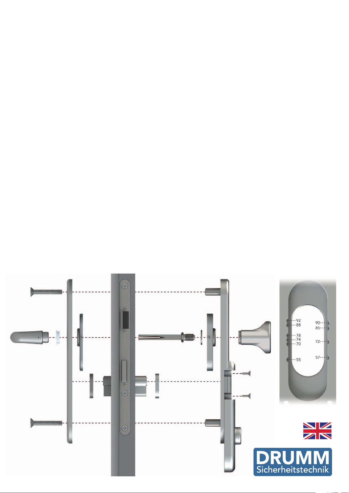
Adjustment of the distance
Use the dimension table to determine the applicable adjustment. Partly screw in the grub screw on the correct side of the insert for
the inner and outer plate. Place the insert in the inner and outer plate. The adjustment dimension refers to the distance from the
middle of the door handle to the middle of the profile cylinders core. The dimensions 72 and 92 mm are standard in Germany.
88 mm is standard in Austria for example.
Preparation of the inner plate
Attach the handle bearing (plastic ring) to the outside of the insert. It prevents subsequent wiggling of the door handle. Insert the
cylinder template.
Preparation of the outer plate
Attach the knob to the outer plate by means of the spindle and the washer. Tighten the spindle with a suitable hexagon spanner, so
that it is secure. Insert the cylinder template.
Assembly of the door fitting
1. Remove the existing fitting from the door.
2. Push the inner plate as a jig on the cylinder on the inside and the outside of the door, align vertically and mark the drill holes for
the fixing screws with a scriber.
3. Next remove the profile cylinder and the mortise lock from the door. This prevents chips from getting into the mortise lock
during drilling and adversely affecting its function.
4. Drill holes with a diameter of 10 mm through the door from both sides at the scribed points.
The drill holes go past the mortise lock.
5. Drill out the top and bottom hole on the outside of the door as a blind hole with a diameter of 13-14 mm and a depth of
approx. 25 mm. Remove the drill chips and refit the mortise lock and the profile cylinder.
6. Loosely screw the outer and inner plate on the door but do not tighten. Ensure that the handle bearing and the profile cylinder
are not twisted in the process.
7. Now tighten the screws. Push the handle on the half spindle from the inside and tighten with the grub screw.
8. Carry out a closing test with the open door.
9. After the function test, check all the screws and retighten if necessary. Over-tightened screws can restrict the function of the
mortise lock. In this case, you can undo the screws slightly.
10. The four wood screws around the cylinder serve as an additional fastening.
This manual suits for next models
3
Table of contents
Languages: