DRYDEN AQUA DA-GEN User manual

7
3
DA-GEN
Dryden Aqua Generator
1
2
1
2
3
4
5
3
4
1
2
3
4
5
5
6
5
6
1
2 3
4
A
B
C
1
2
4
5
6
8
9
10
15
16
7
2
A
B
1
3
9
10
15
16
45
6
8
C
1DESCRIPTION
Electronic box Cell
2SYSTEM INSTALLATION
* Filtration control by external timer
Filtration mode:
“Manual/ON”
230 V
* Filtration control by internal timer
Filtration mode:
See section 5 - Filtration of
the Installation manual
230 VRelais FILTER PUMP
Fuse for device and cell 4 A
Fuse relays 4 A
The DA-GEN is an innovative water treatment system and additional an intelligent pool controller. The DA-GEN
combines Hydrolysis with Electrolysis with a low mineral content.
The Hydrolysis produces free radicals and other oxygen compounds like ozon, peroxide and persulfate. All
these oxidants destroy organic substances and pathogena in the water. Free radicals are the strongest oxidants
we know. They oxidise and decompose in a few seconds. To guarantee a safe depot disinfection the DA-GEN
produces a very small amount of chlorine. In combination with DAISY we need a very low mineral content of 1 to
2 kg MgCl2or 0.75 to 1.5 kg NaCl per m3.
The DA-GEN controls also all your pool components centrally. Thanks to WIFI you can check and control your
pool system 24/7.
110-230 V
Cell
Flow detector
Cell connector
Cell housing
Flow/gas detector (internal)
Connection cell
Flow detector
Main connection 230 V
ON/OFF switch
Flow switch
APF dosing pump
pH dosing pump
pH injection
pH-Minus container
(not included)
External pump controller*
Filter with AFM®
Filter pump
Electronic box
Measuring cell free chlorine
Cell (always in vertical position if
installed without ow switch)
pH probe
Redox probe or conductivity probe
(Optional)
Besgo valve (not included)
WIFI module
Product
Maximum
consumption
DA-GEN 24 125W
DA-GEN 45 180W
DA-GEN 90 175W
DA-GEN 150 680 W
Private
Product
Maximum
consumption
DA-GEN 240 1000 W
DA-GEN 360 1020 W
DA-GEN 500 2880 W
Public
Electrical consumption
It’s recommended to use a time delay circuit breaker of
13 A for private devices and a time delay circuit breaker
of 16 A for public devices. In case of sharing the power
supply with other devices please consult a technician in
order to dimension a correct installation.
USER MANUAL

1
2
3
Adjust the alkalinity between 100 and 200
ppm.
Adjust the pH between 7,0 and 7,4.
Adjust the chlorine between 0,1 and 0,5 ppm.
3INITIAL WATER ADJUSTMENTS
1
2
We recommend to add 1 to 2 kg magnesium chloride or 0.75 - 1.5 kg normal salt
per m3of water. Der TDS should be at around 1200.
Add the magnesium chloride or salt directly to your swimming pool water or in the
compensation tank and let the system run.
•The system will operate without problems with salt concentrations from 1 g/l to 50 g/l.
•In outdoor pools it is necessary to use ACO.
Water adjustments Adding activator/salt to the water
4MAINTENANCE
If necessary, carry out a monthly visual inspection. To clean the cell:
Remove the cell from its support (after turning off the ltration system and closing off the necessary valves).
Place the cell for no more than 10 minutes in 3% hydrochloric acid (1l of acid for each 10l of water).
Once the incrustations have softened remove with a hose to complete cleaning the cell.
DO NOT USE METALIC OR SHARP OBJECTS TO REMOVE INCRUSTATIONS. Scratching the edges or surface of the cell will make it
vulnerable to chemicals, deteriorate the cell and cancel the guarantee.
The pool must be vacuumed as usual and the skimmers emptied whenever necessary.
FILTER BACKWASHING: Once every week for 4 to 5 minutes should be sufcient (providing the lter pressure does not exceed 1 bar, in
which case a lter cleaning may be necessary).
VERY IMPORTANT: Make sure the cell is off while cleaning the lter. If the system controls the ltration pump, use the option “lter cleaning” of the programmed ltration
mode. See section 5– Filtration / Filter Cleaning of the General Installation Guide.
DOSING PUMPS: Check regularly to ensure that the containers contains liquid to prevent the dosing pump of running dry.
pH / Redox / CONDUCTIVITY – PROBES: The probes must be cleaned and recalibrated every 2 to 3 months.
To clean the probe insert in distilled water (clear liquid). After each cleaning the probes must be calibrated. Also: the probes should
never dry out and must be kept wet if stored (when emptying the pool for winterizing, make sure to store the measuring head in water).
~1200 ppm TDS Visual inspection to detect incrustations.
SALT CONCENTRATION: TITANIUM CELL:
1
1
2
2
3
3
4
Cleaning the titanium cell
General maintenance
Monthly checks

5TROUBLESHOOTING
•If salt concentration is correct (1- 2 kg/m3 MgCl2or 0.75 - 1.5 kg/m3NaCl): Cell is reaching its end of life. As of this moment check intensity every 15-20 days.
•When polarity 2 does not reach medium intensity, we recommend substituting the cell for a new one if it happens during the summer period. If it happens during winter,
change the cell before the next summer period.
Polarity 1 reaches maximum intensity, but polarity 2 (auto clean) does not reach maximum intensity
•Check if ON/OFF switch is illuminated.
•Check the connection wire between display and motherboard.
•Check fuse of the device 3.15 A – it could have tripped due to overload.
•Check the power supply – 230V/50Hz.
•If problem persists contact TECHNICAL SERVICE
•Lower electrolysis cell intensity.
•If your system includes automatic Redox control, check Redox setpoint value.
Reduce it by 50 to 100 mV.
•If your system includes free chlorine measurment, adjust the setpoint value.
•Check redox probe and calibrate it if necessary.
Blank display Excess of chlorine in the water
•Low water temperature.
•Check salt concentration (TDS) in water.
•Check cell status (may be incrusted or calcied).
•Clean the cell according to the instructions in section 4.
•Clean the ow detector situated in the cell housing.
•Check titanium cell is not worn out (remember that the cell is guaranteed for
5.000 hours, approx. 2-3 years of summer usage).
Electrolysis does not reach the setpoint value
•Very hard waters with a high pH and total alkalinity: balance water adjusting pH
and total alkalinity.
•Check to ensure the system automatically changes polarity every 300 minutes
approximately.
•Consult with our technical service to consider accelerating the polarity change
(auto-cleaning). WARNING: Accelerating the polarity change decreases the cell
life (5.000 hours) proportionally.
•Reduce pH set point to 7.0
Titanium cell incrusted in less than 1 month
•Check ow detector cable.
•Clean incrustations of ow detector at the top of cell housing.
•Check if system is free of air (probe must be always submerged).
•Metallic elements lack standardized earth connection. Contact an
electrician to solve the problem.
•Rusted components are not stainless steel (minimum 316/V4A/1.4571).
•The salt concentration (TDS) is too high.
Electrolysis display shows FLOW Rust on metallic components in the pool
WARNING
Keep chemical levels in pool as instructed in this manual.
CLEANING FILTER
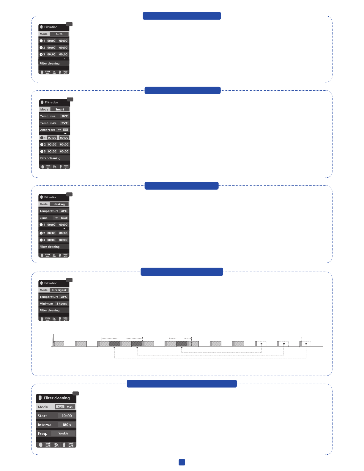
Very Important: Make sure the cell is off while cleaning the lter. If the system controls the ltration pump, use the option “lter cleaning” of the programmed ltration
mode. See section 5 – Filtration / Filter Cleaning of the General Installation Guide.
VERY IMPORTANT
Remember that the system needs some time to adapt to your pool and that you will have to increase chemical levels for the rst 5 days.
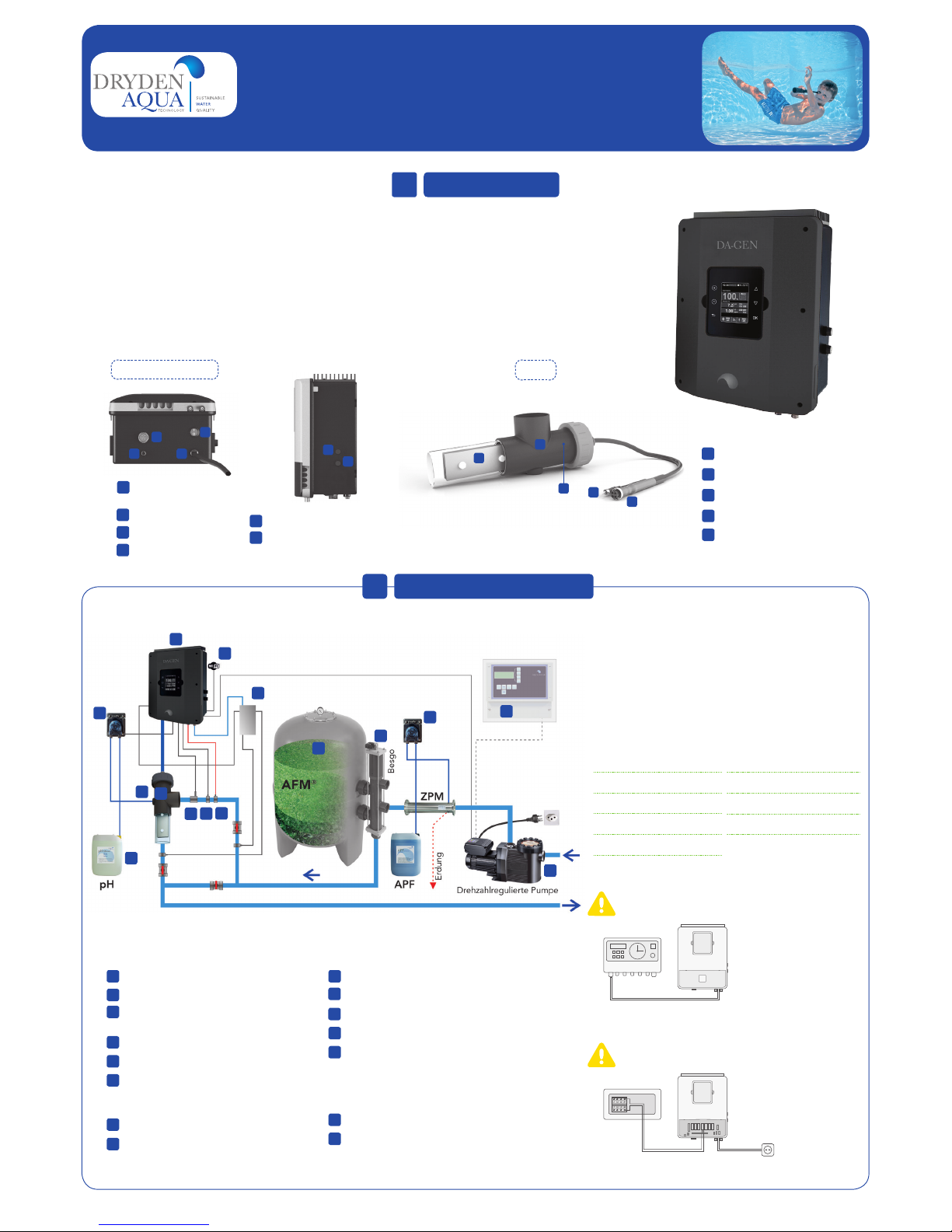
EARTHING
All metallic components in the pool such as lamps, ladders, heat exchangers, drains or similar elements within 3 m from the pool (10 feet) must be connected to an earth
below 37 Ohms. If using heat exchangers, we recommend them to be made of titanium.
SECURITY
To avoid accidents, children should not handle this product unless supervised by an adult. Children should be supervised at all times when in or near a spa, pool or
jacuzzi.
HANDLING AND DOSING DANGEROUS CHEMICALS
Chemicals should be handled with extreme precaution. When preparing acid, always add acid to water, never add water to acid, because very dangerous gasses may be
produced.
•Increase ltration hours to 24 hours
•Increase electrolysis level.
•Check the salt concentraion (TDS) in the water. Setpoint value app. 1200 ppm.
•In an outdoor pool: Add ACO to the water.
•Check if reactive agents in test kit are expired.
•Check if the temperature or amount of users has risen.
Free chlorine level don’t reach the setpoint value
•The maximum dosing time (standard 200 min.) is accomplished and the acid
dosing pump stops in order to avoid the acidication of the water.
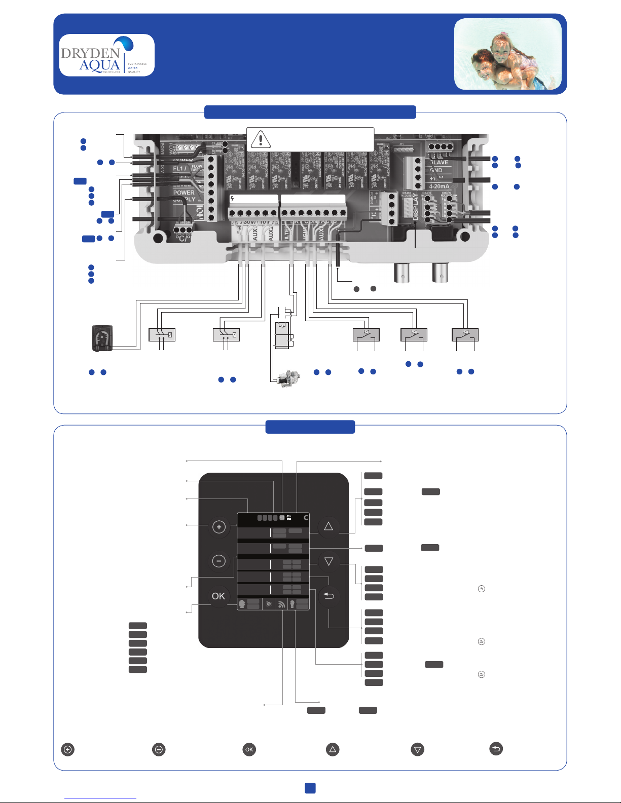
•To delete the message and to restart the metering press ESC ( ). Do the
following verications in order to preclude errors on the device: Verify if the
pH probe reading is correct (if not, calibrate the probe or substitute it with
a new one); Verify if the acid/base deposit is full and if the dosing pump is
working correctly; Verify the variable speed of the dosing pump.
Alarm AL3 and pH dosing pump stopped

DA-GEN
Dryden Aqua Generator
123
1
1
1
2
2
2
3
3
4
4
5
5
6
6
77
88 9 10 11 12 13 14
1 2 3 4
33 3
3
44 4
4
11 1
1
22 2
2
2. MAIN SCREEN
PLUS key
Modify value/selection
MINUS key
Modify value/selection
OK key
Select/conrm
UP key
Navigation up
DOWN key
Navigation down
RETURN/ESCAPE
key
Current time
Production intensity
in %
Communication display – mother board
red indicates communication error
Heating ON/OFF
Manual
Automatic
Heating
Smart
Intelligent
Boost
man
aut
hea
smt
int
bst
State ltration relay
(see section 5- Filtration)
Automatic measurements: pH/redoX/
free chlorine/conductivity (according to options)
State relay lighting
Manual / Automatic
man aut
Water temperature
Polarity 1 / Polarity 2
Filtration stopped due to lack of water ow
Waiting time
Cover
Pol 1
Flow
Low
---
Pol 2
Production automatically reduced to
the % selected (see display 3.6)
Lack of conductivity or salt / low water temperature / scale on
cell / exhausted cell (check working hours)
Polarity 1 / Polarity 2
Pol 1 Pol 2
7.5
7.0
ON/OFF
Setpoint pH maximum (if using pH-Minus)
Setpoint pH minimum (if using pH-Plus)
Function of pH dosing pump
AL3 Maximum dosing time exceeded ( to reset the alarm)
Flow alarm
700
FL 1
ON/OFF Function of chlorine pump
Setpoint redox minimum
AL3 Maximum dosing time exceeded ( to reset the alarm)
Flow alarm / Error rotameter Cl2
AL3
FL 1
1.00
FL 2
Setpoint Free Chlorine minimum
Maximum dosing time exceeded ( to reset the alarm)
Status of the auxiliar relays
1. ELECTRONIC BOX ELECTRICAL CONNECTIONS
Connection remote display*
Connection WIFI module
Device control SLAVE
Variable speed pump
*In case of connecting 2
display´s on the device,
remember not to connect
the remote display in this
communication channel. Use
the “Extern” channel instead.
DRY CONTACT
110-230 V max. 3.15 A
Chlorine probe detector
FL2 (rotameter)
Cover 1& 5
Conductivity probe
Flow switch FL1
2& 5
pH-Minus deposit
level TANK 4& 5
Temperature probe pHredoX
Free chlorine
pH
pH dosing pump
1& 2
AUX 4
Heating control
13 & 14
AUX 3
11 & 12
LIGHT
Lighting control
9& 10
AUX 2
Besgo backwash
valve
5& 6
FILTER PUMP
Filtration control
14
12 11
A1 A2
LN
AUX 1
Dosing pump occulation
APF
3black
5brown
6blue
1red
2yellow
3black
1yellow
2transparent
1slow 2medium
3fast 4common
1red 2yellow
3green 4black
3red 4black
1brown 2blue
7& 8
CONNECT ALL THE SENSORS CAREFULLY, A
BAD CONNECTION MAY CAUSE IRREPARABLE
DAMAGE TO THE DEVICE
TANK Low level chemical tank
1
ISTALLATION MANUAL
12:30 25º
man
off
man
off
CoverPol 1
LOW
00 gr/h
%
hydrolysis / electrolysis
Pr onPol 1
Pol 2
250mA
pH 7.5 OFF
AL37.0
7.2
Rx
mV
700 OFF
AL3FL1
700
Cl
ppm
1.00 FL2
FL1
1.00
Cu/Ag ionization
measures
1 2 3 4
TANK

2
4. MEASURES / SETPOINTS
4.1 MEASURES / pH Calibration
4.2 MEASURES / redox Calibration
3. HYDROLYSE / ELEKTROLYSE
3.1 3.53.2
4.1 4.2 4.3 4.1 Measures: Adjustment of setpoints and measuring probes.
4.2 Setpoints for each measurement.
4.3 Setpoints settings: Ideal setpoints for each of the parameters.
The default values are:
pH: 7.0-7.4; redox: 600 - 800 mV; free chlorine: 0.1- 0.5 ppm;
conductivity: ~ 2000
3.3 3.4 3.6
4.5 4.64.4
4.7 4.8
pH
4.12 4.13
redoX
4.114.104.9
3.1 Hydrolysis/Electrolysis:
Programming of hydrolysis
or electrolysis functions
(according to model).
3.2 Level:
Hydrolysis - Desired
disinfection production (%).
3.6 Cover: connection
of automatic cover.
See section 10-Cover.
3.4 Boost: Filtration during 24h
at max intensity. Automatic return
to programmed ltration mode.
During the boost period the redoX
control can be deactivated.
3.5 Mode: If the device
has Free Chlorine and
redox probes, choose the
parameter that controls the
cell’s chlorine generation.
3.3 Salinity:
Measuring gr/l
of salt in water.
See section
9-Salinity.
Metering and control of
the pH of the water
Optional pH control 4.4 Calibration of pH probe:
Recommended every month during
usage season.
4.5 Calibration with buffers (buffer
solutions pH7 / pH10 / neutral):
Follow the instructions in 7 steps
that appear in the display (screen 4.6
corresponds to step 1).
4.7 Manual calibration: Allows to adjust the
probes at 1 point (without buffers) – only
recommended to adjust small deviation in
the readings.
4.8 Without removing the probe from
the water, use the plus/minus keys to
adjust the reading so it matches with
your reference value (photometer or other
measurement).
The redox value advises us of the oxidation/reduction potential and is used to determine the level of water sterilization. The parameters or setpoints are the minimum/
maximum accepted redox levels before the titanium cell is connected/disconnected. Adjusting the ideal redox level (setpoint) is the last step in the system start up
sequence. Remember to check the redox set-point every 2-3 month and/or if the water parameters change (pH/temperature/conductivity).
Optional redoX control
Metering and control of the
redox as check value of the free
chlorine.
4.9 Calibration of the redox probe:
Recommended every 2 months during
usage season.
4.10 Calibration with buffer (buffer
solution 465 mV): Follow the instructions
in 4 steps that appear in the display
(screen 4.11 corresponds to step 1).
4.12 Manual calibration: Allows to adjust
the probes at 1 point (without buffers) – only
recommended to adjust small deviation in
the readings.
4.13 Without removing the probe from the
water, use the plus/minus keys to adjust the
reading so it matches with your reference
value (photometer or other measurement).

3
4.154.14 4.16
4.184.17 4.19
4.3 MEASURES / Free Chlorine calibration
4.20 4.21
5. FILTRATION / Manual mode
5.1 5.2
110-230 V max. 3.15 A DRY CONTACT
14
12 11
A1 A2
LN
4.4 MEASURES / Conductivity calibration
4.23 4.244.22
4.25 4.26
4.4 MEASURES / Temperature calibration
4.27 4.28
1 2 3 4 5 678910 11 12 13 14
1
2
1 2 3
1
2
3
4
1
2
3
4
5
6
7
8
Metering and control in ppm of
the free chlorine of the water.
Optional Free Chlorine control 4.14 Calibration of the Free Chlorine probe:
Recommended every month during usage season.
4.15 Calibration with buffer (photometer DPD1):
Follow the instructions in 6 steps that appear in the
display.
4.16 Step 1 of 6 - Calibrate Cl at 0 ppm (offset):
Close the water ow through the probe and wait until
the reading is less than 0,10 ppm. Wait between 5 to
60 min. Press OK when the reading is close to 0.
4.17 Step 3 of 6 - Calibrate Cl: Open the water
ow until achieving 80-100 liters/hour. Wait until
obtaining a stable reading of ppm. Wait between 5 to
20 min. Press OK when the reading is stable.
4.18 Step 5 of 6 - Establish the real ppm values
with the plus/minus keys according to your analysis
result of DPD1 (free chlorine).
4.19 Step 6 of 6 - If this screen is not shown repeat
the calibration process.
4.21 Manual calibration: Open de water ow and
set the owmeter (rotameter) at the right level
of ow (80-100l/h). Wait some minutes until the
current level is stable. With the plus/minus keys,
insert manually the water chlorine level (use a
manual DPD1 test kit). Press OK when the DPD1
value is correct on display (target measurement).
Free Chlorine probe
red black
3 4
Chlorine probe detector
FL2 (rotameter)
3
5
6
black
brown
blue
In case of using a Variable
Speed Pump, calibrate
the probe using the most
common ltration speed.
Metering and control of
the conductivity of the
water in Msiemens.
Optional Conductivity probe 4.22 Calibration of the Conductivity probe:
Recommended every month during usage season.
4.23 Calibration with buffer (buffer solution 1413 µS/
12880 µS/ neutro): Follow the instructions in 7 steps
that appear in the display (screen 4.24 corresponds
to step 1).
4.25 Manual calibration: Allows to adjust the probes
at 1 point (without buffers) – only recommended to
adjust small deviation in the readings.
4.26 Without removing the probe from the water,
use the plus/minus keys to adjust the reading so it
matches with your reference value (photometer or
other measurement).
Conductivity probe
1yellow
2transparent
5.1 Filtration:
Conguration control of the lter pump. To set, select
Filtration and conrm by pressing OK . The mode
selection is done in Mode line with the plus/minus keys.
5.2 Manual:
Manually turns ON/OFF the ltration process. No timing
or additional functions. The State line indicates whether
the ltration pump is ON.
See section Filter Cleaning below.
FILTER PUMP
Filtration control
Setup and connection of a Variable Speed
Pump, see section 13 - Variable Speed Pump
7& 8
4.28 Temperature calibration: To set difference
between the measured value of the probe and the
actual temperature, use the plus/minus and up/down
keys. Set to the actual temperature of the probe and
press OK.
Temperature probe
necessary to activate
the ltration modes:
heating, intelligent,
smart.
Optional Temperature
Temperature
probe
1
2
3
red
yellow
black

4
5.1 FILTRATION / Automatic modus
5.3 FILTRATION / Heating mode
5.2 FILTRATION / Smart modus
5.4 FILTRATION / Intelligent modus
5.5 FILTRATION / Automatic backwash
5.5
5.6
0h
10 m in
1h
OFF
ON
3h 5h 7h 9h 11h 13h 15h 17h 19h 21h 23h2h 4h 6h 8h 10h 12h 14h 16h 18h 20h 22h 24h
27ºC 27ºC
28ºC 28ºC 28ºC
5.7 Mode Backwash with Besgo Valve: If the system is equipped with an automatic backwash valve from Besgo, do the follwing settings. A
shut down of the pump is not necessary with a Besgo valve. Use AUX 2!
• Mode: Choose Auto
• Start: Choose starting time
• Interval: Set backwash time in seconds (Recommendation: min. 240 seconds with AFM®, min. 300 seconds with Sand)
• Freq.: Choose frequency (Recommendation: weekly)
5.3
5.4
5.7
5.5 Timed heating with option of climatization*: This mode acts equally to the automatic mode, but besides it includes the option to work on a
relay to control the temperature. The desired temperature is set in this menu, and the system works with a hysteresis of 1 degree (example: the
setting temperature is 23° C, the system will activate itself when the temperature goes below 22° C and will not stop before it passes 23° C).
Use the plus/minus keys to set the desired temperatures and ON/OFF of the Heating.
Clima OFF: The heating only works within the set ltration periods.
Clima ON: Keeps the ltration working when the ltration period is nished if the water temperature is below the setting temperature. When the
setting temperature is reached the ltration and the heating will stop and will not switch on till the next programmed ltration period.
To set the ON/OFF times (up to 3 possible time programmable), follow the instructions of the Automatic Mode.
See section Filter Cleaning below.
5.6 Intelligent*: In this mode the user has 2 working parameters to guaranty the desired water temperature with a minimum of ltration hours:
You select the desired water temperature and the minimum ltration time (minimum of 2 hours and maximum of 24 hours). The device divides
the selected “minimum ltration time” in 12 fragments which start up every 2 hours. If one of these fragments nishes, without the temperature
reaching the desired level, the ltration/heating continues until the desired temperature is accomplished. In order to keep the ltration-electricity-
cost to a minimum, this additional ltration time is subtracted from the following fragments of the “minimum ltration time”. The rst 10 minutes
of each fragment will not be subtracted.
Example (see diagram): Minimum temperature = 28°C and minimum ltration time = 12 hours.
The desired water temperature and the minimum ltration time is set with the plus/minus keys .
See section Filter Cleaning below.
DIAGRAM INTELLIGENT MODE
* Note: Mode only visible if the option to use temperature probe and/or heating is activated in the “Installer Menu”.
5.3 Automátic (or with timer):
In this mode the ltration is switched in accordance with a timer that allow to adjust the start and end of the ltration. Timers always operate daily,
in cycles of 24 hours.
To set the ON/OFF times (up to 3 possible time programmable), select with the up/down keys in the timer line you want to change (1-3 ).
The plus/minus keys opens the selected start time eld. Set the time with plus/minus keys. Scroll with the up key to the minute eld and set it up
with plus/minus keys. To conrm press OK and to cancel press return/scape. To set the OFF timer, proceed accordingly.
See section Filter Cleaning below.
5.4 Smart*: This mode uses, as a basis, the automatic or timer mode, with its 3 intervals of ltration, but adjusting the ltration time in function of the
water temperature. For that reason 2 parameters of temperature are provided: The maximum temperature, from which on the ltration times will be the
ones from the timer setting. The minimum temperature: below this value the ltration time will be reduced to 5 minutes, which is the minimum working
time. Between these 2 temperatures the ltration times will climb linearly.
Use the plus/minus keys to set the desired minimum and maximum temperatures.
There is an option to activate the antifreeze mode in which the ltration will start if the water temperature is below 2° C.
To set the ON/OFF times (up to 3 possible time programmable), follow the instructions of the Automatic Mode.
See section Filter Cleaning below.
* Note: Mode only visible if the option to use temperature probe and/or heating is activated in the “Installer Menu”.

5
AUX 2 5& 6
Automatic
backwash valve
(Besgo)
AUX 1 3& 4
APF dosing pump
7.3
7.3
7.4 7.5
7.6
7. AUXILIARY RELAYS
7.27.1
6. LIGHTNING
6.3
6.4 6.5
6.1 6.2
110-230 V max. 3.15 A DRY CONTACT
AUX 3
11 & 12
110-230 V max. 3.15 A DRY CONTACT
8. SYSTEM SETTINGS
8.8 8.98.6 8.7
8.1 8.3 8.48.2 8.5
8.12 8.14
8.138.118.10
2x
1 2 3 4 5 678910 11 12 13 14
1 2 34 5 6 78910 11 12 13 14
AUX 4
Heating control
13 & 14
7.6 Rename relays: It is posible to rename each auxiliary relay to suit
the use you want to assign. By pressing the plus/minus keys, a pop-up
keyboard will appear. Scroll up and down with the up/down keys and left
to right with the plus/minus keys. To select a letter press the OK.
7.1 Auxiliary relays:
7.2 It is possible to control up to 4 extra auxiliary
relays (water features, fountains, automatic
irrigation systems, built-in cleaning systems,
air pumps for spas, garden lighting, etc.). This
menu displays the relays which are still available
on your device and allow conguration.
7.3 Manual mode (ON/OFF).
7.4 Automatic mode: ON/OFF according to a timer that adjust the start and
end of the program. The timers can be congured with a frequency: Daily;
Every 2 days; Every 3 days; Every 4 days; Every 5 days; Weekly; Every 2
weeks; Every 3 weeks; Every 4 weeks.
7.5 Timer mode: Working time is programmed in minutes. Each time the
key on the front panel in relation to the relay is pressed, it will start up for
the time programmed. This function is recommended for the timing of air
pumps for spas.
6.1 Lighting
6.2 Manual Mode (ON/OFF).
6.3 Automatic Mode: Shuts lights ON/OFF
according to a timer. The timers can be
congured with a frequency: Daily; Every 2
days; Every 3 days; Every 4 days; Every 5
days; Weekly; Every 2 weeks; Every 3 weeks;
Every 4 weeks.
6.4 LED spotlight: In case of having installed led lights in your pool, use
this menu to set the lighting.
6.5 From this menu you can change the color of the lights in your pool.
Select the length of the sign in seconds in Pulse length and press Next
Program option to apply the pulse. Refer to your LED spotlight manual to
set its different colors.
8.9 Sound: Programming of the system to emit sound for the
functions: Keyboard (keys); Notices (pop-up message); Alarms
(working alarm); Filtration (start of the ltration).
8.11 Password: Allows to protect the access to the user´s
menu by activating a password. To enter your password press
a combination of 5 keys and the system will memorize. If you
forget the password, there is a “master password”. Ask your
installer/provider.
8.3 Setting of preferred language.
8.5 Setting of day and current time.
8.7 Setting of the intensity of the
display lighting (0-100%) and
programming its ON/OFF time.
8.12 Cell hours: The system
memorizes the operation times of
the different modules.
8.14 System info: Information about
the available software version of the
TFT display and the power module.
It also shows the ID node which is
necessary for the conguration of
the WIFI connection of the system.
LIGHT
Lighting control
9& 10
The auxiliary relays are congured
by default. If you want to reassign
the relays for other accessories, you
must access the “Service Menu”.
Contact your authorized installer.

6
© Dryden Aqua, 04-2016
8.17 8.18
8.19 8.20
8.15 8.16
8.21
8.1 WIFI SETTINGS
13. VARIABLE SPEED PUMP
13.1 13.2 13.3
13.713.4 13.5 13.6
9.1 9.39.2
9.4 9.5
9. SALINITY* 10. COVER
10.1 10.2
1
2
3
4
5
6
7
8
11. FLOW SWITCH
1
2
3
4
5
6
7
8
12. LEVEL SENSOR (Tank)
3
4
5
6
110-230 V max. 3.15 A POTENTIALFREIE KONTAKTE
12 3 45 6 78 9 10 11 12 13 14
14
12 11
A1 A2
LN
Once the WIFI module is connected to the network with both lights ON, enter in www.vistapool.es.
Access the Register option and enter all the data requested. The unit ID node can be found on your device
(see section 8. System Settings - screens 8.13 & 8.14). Upon completion of the process, you will have
total control of your pool, will be able change parameters such as setpoints, ltration hours and turn ON/
OFF any auxiliary relays.
13.1 Variable Speed Pump: To install a
Variable Speed Pump contact your installer.
13.2 a 13.6 After connecting the pump, you
can individually assign each ltration period
a different speed
F: fast, M: medium and S: slow.
8.15 Internet: Once the WIFI module is connected, restart
your unit. In the Settings menu will appear the Internet option.
8.16 WIFI: Select WIFI to scan the available networks
accessible to the module. The search will be done
automatically.
8.17 Select the desired network accessible to the WIFI module.
8.18 Enter the password in the pop-up keyboard. Scroll up and
down with the up/down keys and left to right with the plus/
minus keys. To select a letter press the OK.
8.19 Conguration: For a more detailed conguration enter
this menu or contact your installer.
8.21 Status: Check the status of your connection.
8.22 Test connection: Check that your connection has been
successfully established.
Connection
WIFI module
Green LEDs
(ON)
1red 2yellow
3green 4black
13.7 Filter cleaning:
To clean the lter
with a Variable
Speed Pump, you
should use the
fastest speed.
10.1 Cover: Connection of automatic cover.
10.2 Reduction of chlorine production in percent, when the pool cover is closed.
With the cover closed is not necessary for the system to run at 100%. With this
parameter, regulates the optimum amount of chlorine generation.
Cover 1& 5
It is possible to add an external
ow switch to the system.
Connect as shown in the image
and contact your installer for
activation. The titanium cell
includes a gas ow sensor, you
can combine both for better
control.
Optional Flow switch
Flow switch FL1 2& 5
Mechanic security
ow switch. Stops the
hydrolysis/electrolysis and
the dosing pumps if there
is no water ow.
9.2 To acknowledge this measure, press OK in Salinity in the Electrolysis/Hydrolysis
menu (the process takes between 2 and 5 minutes - display 9.4). You can adjust the
system measure using a external salt measurer (display 9.5).
9.3 If you do not have a temperature probe, enter the value manually for greater
accuracy. The lecture is inuenced by many factors, like the water temperature or
the pH. Remenber to do the adjustment every 2-3 months.
*Atenttion: Option only available for some models.
9.1 Salinity: The device
shows a measurement
of salt in water in g/l,
as well as the date and
water temperature of
the last reading.
FILTER PUMP
Filtration control
7& 8
Variable Speed Pump
1slow 2medium 3fast 4common
Connect a level sensor to your device so you can control at all times the volume available in the tanks of chemicals that your system
commonly uses. Contact your installer/provider to activate the sensor. This way you can ensure that the dosing pumps never run out of
product and doses in vacuo, avoiding possible damages.
Acid deposit
level TANK 4& 5
8.22
Other manuals for DA-GEN
2
Table of contents
Other DRYDEN AQUA Inverter manuals
Popular Inverter manuals by other brands

Vertiv
Vertiv NetSure 584130100 installation manual

Solar Technology International
Solar Technology International PV Logic PS4001 user manual

Senci
Senci SC13000 Safety instructions & operator's manual

Asco
Asco Series 300 Operator's manual

Inovance
Inovance MD330 user manual

ABB
ABB TRIO-50.0 Quick installation guide

Black & Decker
Black & Decker PI100BB instruction manual

Peimar
Peimar Virtus PSI-J4000-TP user manual

Samil Power
Samil Power SolarRiver 1100TL-S manual

Hoymiles
Hoymiles HMT-1800 Series Quick installation guide

Samlexpower
Samlexpower PST-60S-24A owner's manual

Northern Industrial
Northern Industrial 456900 instruction manual