Drytac HOT PRESS HGP220 User manual

Heated Glass Top Vacuum Press
OPERATOR’S MANUAL
This user’s manual refers to the following models:
6-11-2012
Model Working Area
HGP220 25” x 37” (635mm x 940mm)
HGP260 35” x 47” (890mm x 1194mm)
HGP360 42.5” x 66.5” (1080mm x 1689mm)
HGP560 50.25” x 98.25” (1276mm x 2496mm)

2
Copyright © 2012 Drytac Corporation
All rights reserved. No part of this publication may be utilized or reproduced in a retrieval system, or
transmitted in any form or by any means; electronic, mechanical, photocopying, recording, or otherwise,
without prior written permission from Drytac Corporation.

3
Welcome to the World of Drytac
Over the past three decades, Drytac has evolved into one of the world’s most highly regarded
manufacturers of products for graphics finishing and display. Our core product line consists of a
wide range of pressure-sensitive, heatset and thermal overlaminating films. In addition, we offer
an extensive line of mounting adhesives, backing films, inkjet media, finishing equipment,
accessories, and banner stands.
Our “Start to Finish” strategy sums up Drytac’s unique ability to manage all phases of the customer
experience: product quality and performance, manufacturing and distribution, training and technical
support and the industry’s best customer service.
Thank you for purchasing a Drytac Hot Press
TM
Glass
Top Vacuum Press. The Hot Press Glass Top Vacuum
Press incorporates a proven, high technology heating
system. The top panel of the press is made up of two
sheets of reinforced tempered glass. The inner surface
of the lower sheet has a transparent conductive
coating applied to it. A controlled electric current is
passed through this conductive film creating a highly
efficient heating system. A sensor on the glass
monitors and controls the temperature by means of a
digital thermostat. The transparent top offers a high
level of operator confidence as work can be viewed throughout most bonding processes. The glass
is extremely smooth and scratch resistant.
The Hot Press Glass Top Press handles a wide range of presentation materials from foam board
and wood to photos, art prints and delicate fabrics. The Hot Press brand is well regarded by picture
framers and other finishing professionals for its ability to produce consistent, high quality results.
All models feature an electronic timer with a manual override switch and vacuum pressure
adjustment capabilities. Upon completion of the cycle, vacuum pressure is automatically released
and the timer resets.
To ensure operator safety and to achieve the best results from your Glass Top Vacuum Press, the
machine must be set up and operated in accordance with the instructions in this manual. Please
review the entire manual before using the press for the first time.
We maintain a policy of constant improvement to our products. This means that you may find that
some illustrations and descriptions in the manual may vary from the equipment you are using.
If you have questions concerning applications of the Glass Top Vacuum Press, please give us a
call. Expert assistance is available at no charge. We can also supply many of the adhesives, over-
laminates and other materials used in conjunction with this equipment. For more information,
please contact our Customer Service Department.

4
Table of Contents
Overview...........................................................................................................................3
Safety Considerations.......................................................................................................5
Press Set up.....................................................................................................................5
Stand Assembly................................................................................................................6
Connecting the Vacuum Pump .........................................................................................7
Electrical Connection ........................................................................................................8
Main Controls....................................................................................................................8
Initial Test .........................................................................................................................9
Temperature Controls ......................................................................................................10
Operating the Vacuum Pump............................................................................................9
Principles of Operation......................................................................................................11
Key Processing Factors....................................................................................................11
Fundamentals of Dry Mounting.........................................................................................12
Fundamentals of Laminating.............................................................................................13
Preparing Substrates ........................................................................................................15
Routine Maintenance........................................................................................................15
Troubleshooting, Vacuum.................................................................................................16
Troubleshooting, Electrical................................................................................................17
Contact Information...........................................................................................................18
Warranty...........................................................................................................................19

5
SAFETY CONSIDERATIONS
This product should only be used for the purpose and manner for which it was designed.
Before installing and using the equipment, please read this entire manual and be sure that you
understand all the aspects of proper use. Some of the more important safety considerations
are listed below.
•Ideally, the vacuum press should be used with a metal stand (available from Drytac). If a stand
is not used, the press must be located on a sturdy table or countertop capable of supporting its
weight (refer to Technical data in this manual). The largest model (HGP560) is supplied with a
stand, which must be used due to the weight of the unit.
•Connection of the equipment to the power source must be handled by a qualified electrician
familiar with local and national electrical codes. It is mandatory that the equipment be properly
grounded.
•The gas struts which support the lid are a critical safety item. They must be fully extended (in
other words, the lid must be open completely) in order for them to support the weight of the lid.
The press must be installed in a location which allows the lid to be completely raised without
interference. If the lid is only partially opened, it may close unexpectedly.
•Before each use, the struts should be checked to be sure they are operating properly. Over a
period of time, the struts will lose pressure and will eventually require replacement.
•The inner surface of the glass top is very hot during normal operation. Be very careful
not to touch the glass when inserting or removing materials from the press.
•Before servicing the equipment, it must be disconnected from the power source.
•If either of the circuit breakers on the rear panel of the unit should trip repeatedly, unplug the
equipment and have it serviced. The same applies to the fuses on the side panel.
•The vacuum press incorporates a high-temperature safety cutout device, which disconnects all
power from the unit if the internal temperature reaches a predetermined level (257°F / 125°C).
If the unit unexpectedly shuts off during use and later comes back on after cooling down, it is
likely that this safety device has activated. This indicates a problem with the temperature
control system, and the unit should be repaired by a qualified technician.
•Do not use a knife to cut materials while they
are inside the press. This could cause damage
to the diaphragm.
SETTING UP YOUR NEW VACUUM PRESS
Equipment Location: The smaller vacuum press
models such as the HGP220 and HGP260 may be
used on a table or countertop, provided that it is
able to support the weight of the equipment. The

6
larger models should be used with a floor stand due to their size and weight. The ideal working
height of the press will vary depending on the operator. We suggest a height of 28 to 31 inches
(700 to 790 mm). It is critical that the lid of the press is able to open fully. Please be absolutely
sure that nothing interferes with this!
For proper operation, it is very important that the press be flat and level. The best way to verify
this is to use a carpenter’s (bubble) level. If one corner of the unit is at a different height from the
others, it may be difficult to achieve a proper vacuum. For best results, we recommend that the
press be located away from air conditioning vents, fans
and other sources of moving air.
Unpacking: Carefully inspect the vacuum press for
possible shipping damage. If any is discovered, please
contact our Customer Service Department immediately. If
you are using a floor stand, unpack and assemble it
using the instructions provided. Remove the vacuum
press from the shipping carton and place it on the stand
or table. Leave room to make connections to the rear of
the unit.
Unpack and remove the vacuum pump from its box. The
pump should be placed on or near the floor. There are
suction cups on the bottom of the pump to help keep it in
place, since the pump vibrates during operation. The
pump will become warm during extended usage. If the
equipment is going to be used in a high-volume production
environment, please allow for adequate ventilation of the
area where the pump is located.
Stand Assembly (Model HPG560 Only)
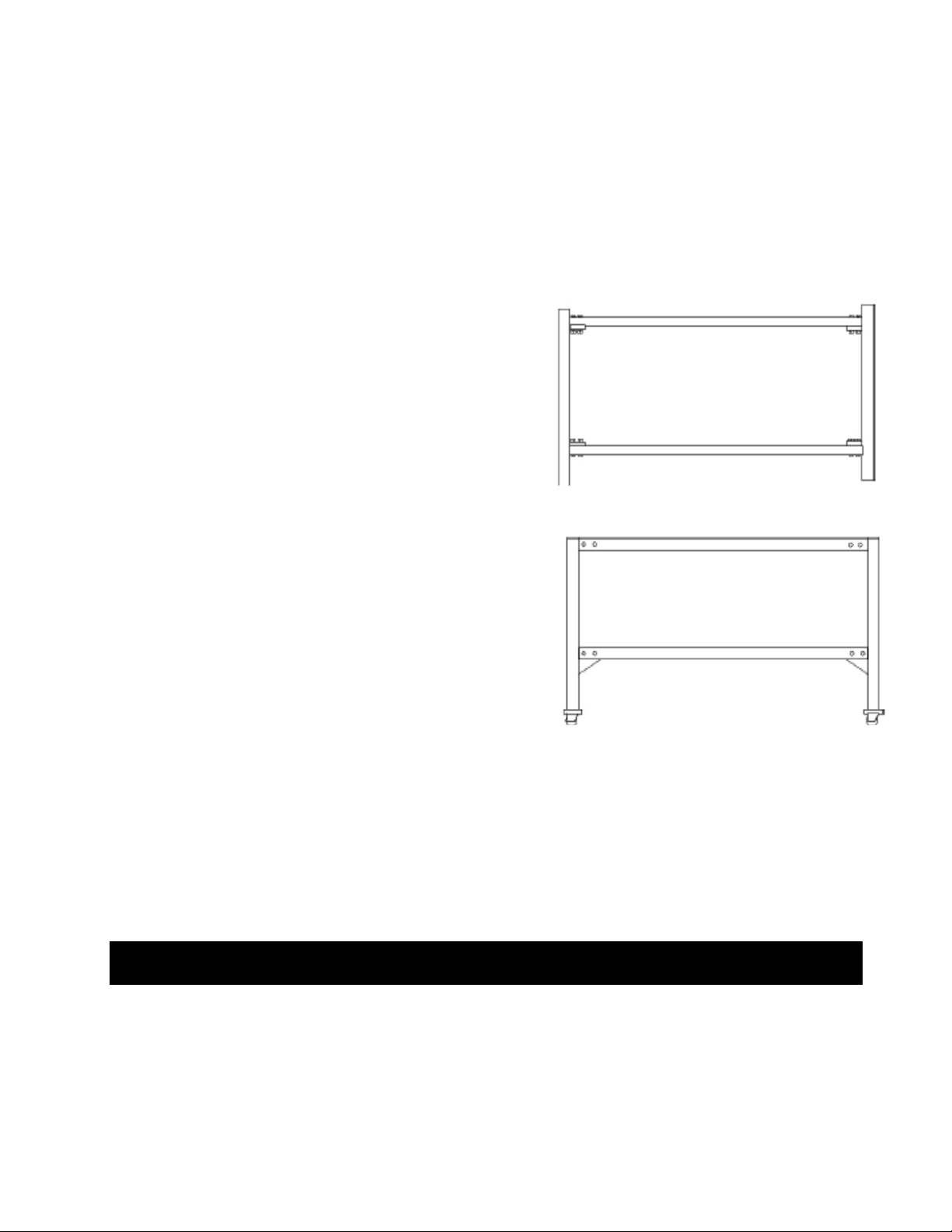
Loosely fit the four tie bars to the ends of the stand (Illustration 4B), using the 16 M10 x 50 bolts,
32 x M10 plain washers and 16 M10 nuts. Tighten all nuts and bolts. Move stand into final position
and ensure that it is level by using the leveling spacers. The stand may be leveled by supporting
the low corner of the stand on the tie bar and removing the wheel. The leveling spacers can then
be inserted between the stand and the wheel assembly and the wheel assembly re-bolted to the
stand. Lower the stand back to the ground and re-check to make sure it is level.
WARNING: THIS OPERATION SHOULD BE CARRIED OUT BY A MINIMUM OF SIX PEOPLE!
The correct functioning of your vacuum press cannot be guaranteed if the press is not
mounted securely onto the stand and the press leveled.
Mount the Press onto the Stand (Model HPG560 Only)
Remove the divider panels from the crate. Remove the screws from the side pieces of crate.
Remove protective packaging from the press. HOLDING THE FRONT AND REAR OF THE
PRESS ONLY AND NOT WITHIN 75 mm OR 3 INCHES OF THE ENDS, lift the press from the
Illustration 4B: Stand Assembly
Illustration 4C: Stand Assembly
Front View with wheels

7
crate onto the stand. Align the press with the ends of the stand. Undo catches at front of press and
raise lid. Remove three screws at front of diaphragm and draw diaphragm forward by
approximately 300 mm or 12 inches. Working from the underside of the diaphragm, remove the
hose(s) from the fittings in the corners of the diaphragm by pushing the collar on the fittings
inwards while pulling out on the hose. Remove the diaphragm from press. Using the 4 M6 x 80 mm
bolts, 8 M6 penny washers, 4 M6 spring washers and 4 M6 nuts, secure the press to the stand by
passing the bolts up through the holes in the stand ends and into the base of the press. Tighten
these nuts and bolts. Insert the diaphragm back into the press and insert the hoses back into the
fittings on the underside of the diaphragm.
Push the diaphragm back into position ensuring it fits into the three clips at the back of the press
and re-fit the three screws at the front of the diaphragm.
Stand Assembly Instructions for Small Models (HGP220 / 260/ 360)
Component list:
•2 x leg assemblies
•2 x top rails
•2 x bottom rails
•12 x rail bolts (16 x for 360) M8 x 60 mm dome head
•4 x press fixing bolts M6 x 80 mm cap head
•4 x penny washers ¼ x 1 “
•4 x lock washers M6
•1 x M6 Allen key
Loosely fit the top rails to the top of the leg assemblies to form a rectangle, using 8 of the M8 x 60
mm bolts. Loosely fit the bottom rails, about half way up the leg assemblies, using the remaining
M8 x 60 bolts. Tighten all bolts using the Allen key and ensure stand is steady. The top rails are
inset from the front and rear, the largest inset is the front of the stand. Lift press onto stand. Fit M6
x 80 mm bolts with lock washers, then with the penny washers, then insert them up through the leg
assemblies into the base of the press. Tighten the bolts (using the Allen key) until rubber press feet
are compressed slightly.
CONNECTING THE VACUUM PUMP
A length of plastic vacuum tubing (either red or green,
depending on the model) is supplied with the equipment.
Connect one end to the pump and the other end to the rear
of the vacuum press. No tools are needed - the tubing is a
simple “push fit” into the special connectors. You will feel

8
two stages of resistance as the tube is inserted. The ends of the tubing must be clean and smooth
to ensure a good seal. If damaged, simply cut off 1/4” (5mm) with a sharp knife. To remove the
tubing, press the end of the metal fitting and pull the tubing out.
Plug the electrical cord from the pump into the matching connector on the rear of the vacuum
press.
All four models of the Drytac Glass Top Vacuum Press require single-phase AC power. The
current and power requirements are different for each model, and are summarized below.
Electrical Specifications
Model HGP-220 HGP-260 HGP-360 HGP-560
Voltage
220
-
240 VAC
50/60Hz
220
-
240 VA
C
50/60Hz
220
-
240 VAC
50/60Hz
220
-
240 VAC
50/60Hz
Current 10A 11A 18A 25A
Current
((peak)
11A 13A 22A 28A
Power 2.3 KW 2.5KW 4.2KW 6.7KW
Circuit 20A 20A 30A 40A
Please be sure to provide adequate ventilation if the equipment is to be used in a high-volume
production environment.
Make certain that the power source conforms to the requirements specified above. All local
electrical and safety codes, as well as the current National Electrical Code (NEC) must be
followed. All wiring must be installed by a qualified electrician.
To reduce the risk of electrical shock, the vacuum press must be used only with a properly
installed 3-wire grounding-type receptacle and plug combination. Do not use extension cords or 2-
prong adapters with this equipment. Proper grounding of the receptacle must be verified before
use.
The electrical cord should be routed and secured so that it does not present a hazard. Protect the
cord at all times from sharp objects, hot surfaces, oil and chemicals. Avoid kinking the cord.
Periodically inspect the cord and plug, and replace immediately if worn or damaged.
Disconnect the equipment from the power source before moving or servicing.
PRESSURE ADJUSTMENT KNOB: Adjusts pressure for applications such as mounting onto
foam boards.
Illustration 7A:
Main Controls

9
VACUUM PRESSURE GAUGE: Indicates actual vacuum pressure. A normal reading is 25” or
higher (with the variable pressure adjustment set to maximum).
AUTO / MANUAL SWITCH: Acts as a simple On/Off switch for the pump if you do not need to
use the Timer.
TIMER CONTROL: Controls the vacuum pump and pressure release valve. At the end of the
preset cycle, the pump will turn off and the vacuum will be automatically released.
POWER SWITCH: Switches on the heating system and the timer.
TEMPERATURE CONTROLLER: Indicates the actual glass temperature and maintains the
temperature at your chosen preset level.
INITIAL TEST
Test the GFCI (Ground Fault Circuit Interrupter) circuit breaker. It is the circuit breaker located
nearest to the center of the rear panel of the press. It should be tested after installation (and
periodically thereafter) to ensure that it is functioning correctly. To test it, press the test button
(labeled “T”) adjacent to the breaker handle. The breaker should immediately trip. If it does not, the
GFCI is defective and must be replaced. Note that the equipment must be connected to a power
source in order to perform this test.
Verify that both of the circuit breakers on the rear panel of the press are in the ON position (levers
pointing to the right). Check that the Auto/Manual switch located on the front panel is in the AUTO
position, and that the power switch is in the OFF position. Connect the power cord to the electrical
outlet. Remove any materials from inside the press, then close and latch the lid. Turn the Pressure
Adjustment Knob fully clockwise (maximum vacuum).
Turn on the power switch on the front of the press. The displays on the Timer and Temperature
controllers should light up. The Timer will normally indicate 2:00 and the temperature controller will
indicate room temperature. Within a minute or so, it will start to increase. After about 15 minutes,
the temperature should reach the setting that was preset at the factory, normally 194°F (90°C).
Now press the Start button on the timer (the one in the upper right corner). The vacuum pump
should start, and the timer should begin to count down. Within a few seconds, the pointer on the
vacuum gauge should start to move. Within 30 seconds, the reading should be steady at 25” or
higher.
When the timer reaches zero, the pump should automatically cut off, and the vacuum should
automatically be released. Check the vacuum gauge, which should now be back at a zero reading.
Illustration 7B: Press Start Button to begin initial test.

10
ADJUSTING THE TEMPERATURE CONTROLLER (FARENHEIT)
To adjust the pre-set temperature, press and hold Button1. Then use Button 2 to increase or
Button 3 to decrease the pre-set temperature. Once the desired level is reached, release Button 1
to set the desired temperature.
When current is flowing through the heating element, a small red dot next to OUT1 will glow. In
normal operation, the dot will turn on and off every few minutes as the controller maintains the
glass at the preset temperature.
At the factory, the temperature controller is set to allow a maximum temperature of 239°F. The
factory preset temperature is 194°F.
ADJUSTING THE TEMPERATURE CONTROLLER (CELSIUS)
To adjust the preset temperature, press Button 1 and L1 will appear for one second. Then press
Button 3 to increase or Button 4 to decrease the preset temperature. Once the desired level is
reached, press Button 1 to set your required temperature.
When the current is flowing through the heating element, a small red dot next to RL1 will glow. In
normal operation, the dot will turn on and off every few minutes as the controller maintains the
glass at the preset temperature.
At the factory, the temperature controller is set to allow a maximum temperature of 115°C. The
factory preset temperature is 90°C.
Should you press Button 4 in error and HY1 displays, just press Button 1 again. Do not change
the value that follows HY1.
OPERATING THE VACUUM PUMP (Timer)
Automatic Control
For automatic control, the pump switch should be set in the AUTO
position. The Timer controls the length of the cycle in minutes and
seconds.
The Timer has three operating modes:
•Set – Normal mode. The timer is ready to operate.
•Pgm – Program mode. 6the preset time may be changed.
•Hand – Manual mode (see “Manual Operation”) below.
When in Set mode, the timer displays the preset time.
Illustration 8A: Temperature Controller (F) Illustration 8B: RL1 Dot

11
Illustration 10A
: Key pr
ocessing factors
When in Program mode, either the minutes or seconds digits will be flashing to indicate that you may
change them as desired.
To Change the Preset Time
Enter the Program mode by pressing Button 1; either the minutes or seconds digits will flash. To
alternate between minutes and seconds press Button2. Use Button 3 to increase or Button 4 to
decrease the time. Once the desired value has been set, press Button 1 to return to set mode.
To Start the Vacuum Cycle
In Set mode (when no digits are flashing), press Button3 to start the cycle. The timer will indicate
that the pump is on and begin to count down. Once the preset time has elapsed, the pump will
stop, the vacuum will be released and the counter will return to showing the preset time.
If you wish to stop the cycle part way through, simply press Button 4. This will stop the pump,
release the vacuum and reset the timer.
MANUAL OPERATION
Switching the PUMP switch to MANUAL position will cause the pump to start. The pump will run
until the switch is returned to the AUTO position.
The Timer also has a manual mode, which allows it to be used as a simple On/Off switch. Press
Button 2 depressed, press Button 1. The timer will display the word hAnd. Pressing Button 3
(start) will switch the pump on; pressing Button 4 (stop) will switch it off. To return to automatic
operation, press Buttons 2 and 1 as described above. Although this facility is available, we
recommend that you use the AUTO/MANUAL
switch rather than the “hAnd” function.
PRINCIPLES OF OPERATION
Your Hot Press Glass Top Vacuum Press is
precision engineered to deliver the optimum heat
and pressure for a variety of mounting and
overlaminating applications. A conductive
coating is applied to the upper surface of the
lower of two sheets of tempered glass that form
the lid of the press. When an electrical current is
applied to the coating, the glass heats up in a
very even and consistent manner. When the lid
is closed onto the gasket around the outside of
the bottom frame, it forms an airtight chamber from
which air is drawn out by the vacuum pump. The vacuum causes the flexible diaphragm in the
base, and any materials placed on it, to be pressed against the glass, thus applying the heat and
pressure needed to bond materials together.
KEY PROCESSING FACTORS
There are three key processing settings that apply to virtually all mounting and laminating jobs.
•Temperature
•Time (Dwell)
•Pressure
Temperature: The temperature setting is primarily dictated by the requirements of the heat-
activated adhesives used in the dry mounting tissue and the over laminating film recommended for

12
your job. It is important that the press be operated at the correct temperature to activate the
adhesive and bond the materials. See page 8 for more on temperature controls.
Time (Dwell): This factor works in conjunction with temperature to create a permanent bond
between materials. Assuming that the temperature setting of the press is sufficient to activate the
adhesive, it is almost always preferable to increase dwell rather than temperature. Dwell time is
set using the Timer (page 9) and dictates the vacuum cycle (see Pressure, below).
Pressure: Pressure is established in the press by the vacuum pump, which is controlled by the
Timer (see page 9). The vacuum presses the materials together for the amount of time chosen by
the operator using the timer controls. Pressure should usually be set at over 25” of mercury. It
should be reduced for softer mounting materials such as foam board using the vacuum adjustment
valve.
Other Factors: Following the recommended temperature and time settings on your Glass Top
Vacuum Press will almost always produce excellent results. However, other factors can affect the
settings on the machine.
Materials: Manufacturer’s dwell and temperature settings are based on paper graphics.
However, heavier materials such as canvas absorb more heat and may require a higher
temperature setting or longer dwell time setting. This is also true for denser or thicker mounting
substrates.
Workpiece size: The same principle applies to the overall size of the job. Larger jobs absorb
more heat and may require longer dwell times.
NOTE: Whenever possible, test actual materials together prior to processing a challenging or
unusual job.
FUNDAMENTALS OF DRYMOUNTING
Dry mounting an image to a substrate can be performed
in a variety of ways and varies according to the nature
of the mounting substrate, mounting adhesive and the
print, photo or artwork being mounted. However, the
basic methods described below will provide excellent
results for most standard applications.
1. Set the vacuum press to reach an operating
temperature of 185°F (85°C)*.
2. Cut a piece of dry mounting tissue slightly larger
(on all sides) than the work to be mounted.
3. Place your print face down onto a clean work surface and cover with the dry mounting
tissue. Lightly tack the tissue to the back of the print with a tacking iron. To avoid adhesive
building up on the tacking iron, tack through silicone release paper/film, shiny side toward
the tissue. Trim the excess tissue.
Illustration 11A
:
Top to bottom
Material
placement
order in press

13
Illustration 11
B
:
Tacking dry
mounting components
Illustration 12A: Top
to bottom
material placement order in
p
ress.
4. Place the print, with the tissue attached, onto the mounting substrate. Lift the opposite end
of the print/mounting tissue and tack the mounting tissue side directly onto the mounting
substrate.
5. Place the three components into the press between two sheets of release paper/film for
approximately 30 seconds to 3 minutes*- from the time the press has achieved the desired
pressure setting.
Processing Tips:
•Maximum vacuum pressure is recommended – except when mounting onto foam board, as
this type of substrate may be subject to “crushing”. When mounting onto foam board, we
recommend using reduced vacuum pressure during the mounting cycle.
•We recommend silicone coated clear release paper. Clear release film is transparent
(allowing you to see the work in progress), less prone to “creasing” and has a longer usage
life.
•The diagram in Illustration 11A shows the positioning for each component in the dry mount
package prior to being placed in the press.
NOTE: Clear release film or silicone release paper must be placed on top of the “mounting
package” to prevent any exposed adhesive from sticking to the glass.
FUNDAMENTALS OF LAMINATING
Laminating is the process of applying a thin clear film to the surface of a print, photograph or other
type of graphic. Drytac manufactures a wide range of Artshield™ UV HeatSet laminating films for
use with the Hot Press. The materials are activated by temperatures in the 185°F-210°F (85°C-
99°C) range, with processing times ranging from 2 – 10 minutes. Please check the specific
product recommendations before laminating.

14
Illustration 12
B
:
Applying Artshield laminate
to the print/photo.
Your actual settings will vary according to the size of the press, type of dry mounting tissue, type of
mounting substrate, the artwork material used (in terms of material and the size of the print. See
specific product specifications for recommended dwell times (dwell times provided are for paper
graphics).
1. Cut a piece of ArtShield™ UV HeatSet laminating film (or other appropriate heat activated
laminating film) approximately ½” (1cm) larger (on all sides) than the print to be laminated. At
this stage, your print may already be mounted or, ifyou choose, you may dry mount at a later
time without affecting the laminated finish (refer to step 8 below).
2. If the print/graphic to be laminated has a non-breathable surface such as a resin coated (RC)
photograph, it will be necessary to sue a pre-perforated ArtShield laminating film. If the
selected film is not pre-perforated, place it onto a cutting mat or card stock with the film surface
face up. Using a perforating tool, lightly pierce the film in a crisscross pattern; ensuring the
holes are approximately ¼” (6mm) apart.
3. A release paper backing protects the adhesive coated side of the laminating film. Peel this
back approximately 1” (2.5cm), exposing one edge of the laminating film. Place your print face
up on a clean work surface. Position your laminate on top, exposed adhesive edge down.
While holding it firmly on the table with one hand, gently pull the release paper away and
toward you from underneath.
4. Check that there is no dirt or dust trapped under the laminating film. If necessary, the film may
be gently lifted, the contaminants removed and the film repositioned.
5. Using a burnishing pad or soft cloth, lightly smooth the laminating film down onto the print to
remove excess air bubbles.
6. Place the print onto a larger piece of silicone release paper/film shiny side up.
7. Preheat your press to 180-210°F (82-99°C)*.
8. Cover your work with the foam overlay blanket and place into the press.
9. Your work piece should be processed for two to ten minutes* - beginning from the time that the
press has achieved the desired pressure setting.
10. The final result should be a blemish-free finish. If any silvering is apparent under the clear film
(especially visible in the dark areas), re-insert and process for an additional 2-10 minutes*.
Caution: ArtShield
™
Glossy laminating film cannot be pierced and is not recommended for
photographs.

15
Illustration 1
3A
:
Using TacCloth
to wipe down foam board.
Note: Put the foam overlay blanket directly on top of laminating film. Do not put release paper/film
between film and foam overlay blanket or between foam overlay blanket and top of press.
PREPARING YOUR MOUNTING SUBSTRATE
Once you have decided on the most appropriate
adhesive/substrate combination for your application, it is
important that you properly prepare your substrate before
coating. Although often overlooked, this can be the most
important step when mounting a print or artwork for display.
FOAM BOARDS: (E.G. FOME-COR®, ETC)
The surface of these types of substrates is porous and often
contains particles that can spoil an otherwise perfect mount.
Clay-coated surfaces such as Fome-Cor®, Foam-X® and
similar boards should be wiped with a TacCloth
™
to remove
dust particles.
MAT BOARDS/MILL BOARDS
To prepare mat board or millboard for mounting, use the Anti-
Static Wisk
™
brush to remove dust particles and other debris.
HARDBOARD: (E.G. MEDICUM DENSITY FIBERBOARD, MASONITE, ETC.)
To prepare hardboard substrates for mounting, wipe down the surface with a TacCloth. Should the
surface contain irregularities, use sandpaper to remove them, then wipe the surface with a
TacCloth.
Please note: Due to their highly absorbent properties, do not wipe down the surfaces of any of
these substrates (i.e. foam board, mat/millboard or hardboard) with a moist rag.
ROUTINE MAINTENANCE
Cleaning: Each day before using the press, check the pump filter bowl for water. To drain the
bowl, ensure the pump is turned off, then simply unscrew the bowl, dump the water out and re-
attach the bowl. If the press is used for mounting on foam board, the water trap may have to be
emptied quite frequently. Do not allow the bowl to become full, as this may allow water to enter the
vacuum pump and cause serious damage.
Use a brush or vacuum to remove dust and debris from the rubber diaphragm as needed. Keeping
the diaphragm clean will help prevent the pump filter from becoming blocked.
Clean all the way around the grey silicone seal with a damp cloth, checking for foreign matter and
cuts. If any adhesive has accumulated on the glass, it may be dissolved with acetone or nail polish
remover. Do not use abrasive cleaners. A single-edged razor blade may also be used, but be
careful not to scratch the glass. The outside of the press may be cleaned with any standard, non
abrasive household cleaner.
Tip
:It is important that you remove dust and other debris from your prints prior to mounting.

16
Illustration 1
4
A
:
Adjust latches if
they don’t close with a soft “click”.
Illustration 14B: Hinge adjustment
Latch Adjustment: The latches on the front of the unit
should close easily with a comfortable “click”. If they are too
loose or if they need excessive pressure to close, they can
be adjusted by turning the latch on the pivoting, threaded
shaft. Adjust only one turn at a time. Lengthening the
amount of threaded shaft visible (by turning clockwise) will
loosen it. Overtightening the latches will not improve
effectiveness of the vacuum seal and will cause the latches
to wear out prematurely.
Hinge Adjustment: The hinges at the rear of the press are
designed so that they can be easily adjusted to ensure a
good vacuum seal. Make sure that both hinges are adjusted
by the same amount to keep the press lid level. The top part
of the hinge is bolted to the top frame and cannot be moved.
Adjustment is carried out on the bottom part of the hinge.
Both bolts pass through elongated holes in the frame. Should
it become apparent that the grey sealing gasket is not in
contact with the underside of the lid across the entire back of
the press, the adjustment procedure is as follows: Close the
press; loosen both bolts “A” half a turn. Turn on the vacuum
pump. Using a wrench, turn bolt “B” on each hinge a little at a
time until a vacuum is pulled. Only a small adjustment will be
required. Re-tighten both bolts “A”.
Vacuum Pump: The vacuum pump is built with sealed, permanently lubricated bearings and does
not require lubrication or other periodic maintenance other than cleaning the filter and water trap.
VACUUM TROUBLESHOOTING
The vacuum gauge should indicate approximately 25” of mercury during normal operation. If the
reading is too low, or the press takes a long time to “pull a vacuum”, check for one or more of the
following common problems:
1. Foam or other materials trapped in the seal:
It is very easy for the foam overlay blanket to
become misplaced and inadvertently become
trapped in the seal. This will allow air to leak in,
preventing a good vacuum from forming. Foam
used in the press will tend to expand over time.
As this happens, you should lay it on the bench
and trim a strip off each edge. Also check for
paper, canvas or other materials that may be
stuck to the lid and interfering with the seal.
2. Press is not level: If all four corners of the
press are not level, it may be difficult to achieve
a proper vacuum. Use a carpenter’s (bubble)
level to verify. If one corner is out of alignment, use shims under the press as necessary to
correct.

17
3. Misalignment of press lid: To verify this, do the “bookmark” test. Cut thin strips of paper and
place at different sections of the seal all the way around the press. Close the lid and secure
the latches, then try to remove the paper strips. The paper will normally be held tight. If the
paper can be pulled out, this will indicate there is a gap between the seal and the lid of the
press.
Normally, this can be resolved by adjustment of the hinges at
the rear of the press. Refer to the Routine Maintenance
section for the procedure.
A gap at the front of the press may also indicate that the
latches need to be adjusted. The latches should snap shut with
a firm “click” but should not be difficult to close. If they are too
loose, follow the adjustment procedure in the maintenance
section. Do not over tighten the latches, as this will cause them
to wear out prematurely and will not improve the vacuum.
4. Diaphragm has split or has been cut: Inspect the
diaphragm carefully for holes, particularly around the edges
and in the corners. Small holes can be repaired with a
bicycle tube repair kit. (Apply the patch to the bottom of the
diaphragm.) If necessary, the diaphragm can be removed
from the press for inspection. Be sure to disconnect the
press from the power source before taking the diaphragm
out.
5. Internal vacuum leakage: Put your thumb over the hole in
the rear corner of the diaphragm and observe the reading on the vacuum gauge. If the reading
is still too low, check the following:
a. Check that all vacuum hose connections are tight.
b. Check the pump filter for blockage. Ensure the pump is off, then unscrew the filter
bowl, pull the filter cartridge out and refit the bowl. If this fixes the problem, the filter
element will need cleaning. Unscrew the retaining plate at the bottom of the cartridge
and withdraw the filter element, wash in household detergent and re-assemble.
ELECTRICAL TROUBLESHOOTING
1. Press shows no readings on temperature or timer controls:
•Check the two circuit breakers on the rear panel of the unit. The levers should both be pointing
to the right (as seen from the back). Some models have circuit breakers with a color code –
green indicates off, and red indicates the on position.
•Check power source – verify that the power cord is firmly connected, and that the power outlet
is live. If it is not, check the circuit breaker at the building’s electrical distribution panel.
•Unplug the power cord and check the fuses on the left side of the unit.
2. Press starts up normally, then overheats and shuts off, or the temperature controller
displays an error code such as “PFA” or “LOR”.
•Check heater relay.

18
CONTACT INFORMATION
Drytac Corporation (USA) Drytac Europe (UK)
5601 Eastport Blvd. Filwood Road, Fishponds
Richmond, VA 23231 Bristol BS16 3RY, United Kingdom
Toll Free Phone: 800-280-6013 Phone: +44 (0) 117-958-6500
Toll Free Fax: 800-622-8839 Toll Free Phone: 0845-070-0660 (UK only)
Drytac Canada, Inc.
220 Caldari Road
Concord, Ontario
Canada L4K 4L1
Toll Free Phone: 800-353-2883
Toll Free Fax: 877-437-9822
Hot Press
™
Registration Information
C
OMPANY
N
AME
:
A
DDRESS
:
C
ITY
/
S
TATE
:
M
ODEL
#:
S
ERIAL
#:
P
URCHASE
D
ATE
:
W
ARRANTY
C
ARD
R
ETURNED ON
:
BY:

19
WARRANTY
We thank you for your purchase of the Hot Press
TM
and want to assure you that we will do our best
to see that your experience with your new machine is a positive one. Every Drytac machine is
designed and manufactured to give many years of dependable service.
To achieve the best results from your new press, it should be set up and operated in accordance
with the instructions included in this manual.
The Hot Press
TM
warranty covers parts for twelve months and labor for three months from the
purchase date. During the first three months of the warranty period, Drytac or their dealer will
arrange for the machine to be repaired, replaced or refunded at Drytac’s discretion. (Excludes
shipping and travel costs). Rollers are guaranteed for 3 months against manufacturing defects.
After the warranty period has expired, Drytac will provide all reasonable assistance and product
support to resolve any problems that may arise.
Please return your warranty card as soon as possible. This will help us more efficiently assist with
any problem you may encounter. You will find a section for recording this important information for
your records and any future parts or service requests on page 18 of this manual.
Normal wear and tear, any damage to the diaphragm (other than a manufacturer defect), damage
due to abuse, improper operation or installation is not covered by this warranty. Conditions that
will void the warranty include, but are not limited to: failure to follow the instructions contained in
this manual, unauthorized changes or modifications to the machine or the stand (where applicable)
in any manner or misuse of the machine for purposes other than specified in the Operators
Manual. Drytac will not be responsible for any damage or consequential damage caused by the
machine. Please feel free to contact Drytac if you have any questions or problems.
Before calling Drytac Technical Services, complete the Hot Press
TM
Registration Information on the
previous page and have it available for reference.
Other manuals for HOT PRESS HGP220
1
This manual suits for next models
3
Table of contents
Other Drytac Power Tools manuals
Popular Power Tools manuals by other brands

Bosch
Bosch GBM 16-2 RE Professional Original instructions

Pattfield Ergo Tools
Pattfield Ergo Tools PE-AGS 3,6 Li Original operating instructions

Ryobi
Ryobi RSDP4 manual

Tradeflame
Tradeflame PRO HEAT 10000594 product manual

Makita
Makita HM0810B instruction manual

Bosch
Bosch GHG 16-50 Original instructions