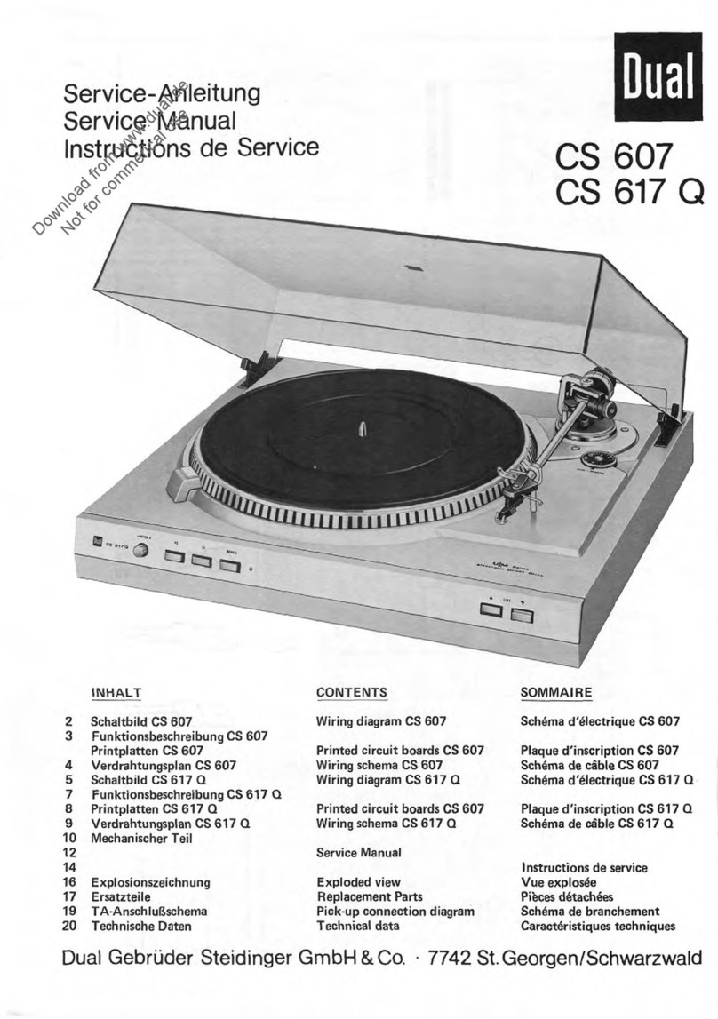
Dual 622 User manual

Service
Manual
Technical
Data
Currant
Line
voltage
Drive
Power
input
Power
consumption
Time
from
start
to
rated
speed
Platter
Platter
speed
Pitch
control
Speed
control
(monitoring)
Sensitivity
of
the
illuminated
strobe
(for
0.1
%
speed
deviation)
Total
wow
and
flutter
(according
to
DIN
45507)
Rumble
(according
to
DIN
45500)
Tonearm
Effective
length
of
tonearm
Offset
angle
Tangential
tracking
error
Tonearm
bearing
friction
(related
to
stylus
tip)
Stylus
pressure
Cartridges
Weight
Dual
622
Edition
January
1980
AC
50
to
60
Hz
110
to
125V,
220t0
240V
electronically-controlled
direct-drive
system,
Dual
EDS
500
Motor
at
playing
operation
approximately
2
watts
<50
mW
220
V
50
Hz:
at
start
35
mA
110
V60
Hz:
at
Start
65
mA
at
play
15
mA
at
play
approximately
25
mA
2-
2.5s
at
33
1/3
rpm
non-magnetic,
1.4
kg,
304
mm
diameter
33
1/3
and
45
rpm,
electronically
adjustable
Separate
for
both
speeds,
each
adjustable
by
means
of
variable
resistor,
with
calibration
scale;
range
of
regulation:
10%
with
illuminated
stroboscope
for
platter
speeds
33
1/3
and
45
rpm,
adjustable
to
50
or
60
Hz
6
division
markings
per
minute
at
50
Hz,
7.2
division
markings
per
minute
at
60
Hz,
(German
Industry
Standard)
±
0.05
%
WRMS
±
0.03
%
Unweighted:
50
dB
Weighted:
75
dB
Torsionally
rigid
tubular
aluminum
tonearm
in
low-friction
four-point
gimbal
suspension
221
mm
24
0
4'
0.16
0
/cm
vertical
<
0.07
mN
(0.007
g)
horizontal
<
0.15
mN
(0.0159)
from
0
to
30
mN
(0
to
3
g)
infinitely
variable
with
1
mN-
(1/109)
calibrations
from
0
to
15
mN
(0
to
1.59)
operable
from
2.5
mN
(0.259)
stylus
pressure
up.
with
1/2
inch
screw-type
attachment.
These
can
be
fitted
with
the
special
accessories
no.
262
186
which
can
be
obteined
from
trade
dealers.
ca.
5.4
kg
Dimensions
and
Cutout
Required
refer
to
Installation
I
nstructions,.
Download from www.dual.de
Not for commerical use

Contents
Page
1
Technical
data
2
Audio
connection
diagram
3
Wiring
diagram
4
Dual
EDS
500
eelctronic
direct
drive
system
4
Replacement
of
motor
electronic
4
Replacement
of
motor
mechanic
4
Adjustment
of
nominal
speeds
4
Setting
78
rpm
nominal
speed
5
Stroboscope
5
Pitch
control
5
Tonearm
and
tonearm
suspension
6
Removal
of
tonearm
or
spring
housing
6
Removal
of
tonearm
compl.
with
tonearm
suspension
6
Adjustment
of
tonearm
suspension
6
Fitting
1/2
inch
pick
-up
6
Antiskating
control
7
Cue
control
7
Replacement
of
cue
control
assembly
7
Tonearm
Control
7
Muting
Switch
8
Continuous
Play
8
Start
8
Manuel
Start
8
Stopping
9
Shutt-off
Mechanism
9
Adjustment
Points:
Tonearm
set
Down
Point
9
Shut
off
Point
9
Tonearm
does
not
set
down
9
Vertikal
Tonearm
lift
10
Correct
nominal
speed
obtained
only
at
extreme
setting
of
pitch
control
10
Platter
does
not
start
10
Tonearm
does
not
set
down
correctly
10
Motor
does
not
shutt-off
10
Acoustic
feedback
1
0
—
13
Replacement
vvith
exploded
views
14
Lubrication
Fig.
1
Audi
Connection
Diagramm
Kontaktplatte
Contact
plate
Plaque
de
contacts
rechter
Kanal
right
channel
Canal
droit
Kurzschließer
Muting
switch
Court-circuiteur
/
—
\
rot
/
red
/
rouge
/
s
r
I
1
I I
I
I
grün
/
green
/
lieft
‘,
/
\
/
\_,
schwarz
/
bleck
/
negro
,-,
blau/blue/bleu
/
\
/
\
1
I I
I
I
weiß
/
white
/
blanc
\
/
\
/
\
—/
L
linker
I.anaI
left
channel
Canal
gauche
Cynchstecker
DIN-Stecker
5-polig
phono
plug
DIN-plug
5
pin
fiche
cynch
fiche
DIN
5
püles
•
Masse
draht
Mass
lead
Mass
cäble
•
•
2

r
r
r
Dl
7,s
cl
47
p
1.1
2
•
66
2/3
Hz
(33
min
1
)
IV
C2
C3
220p
0,47
—
IR
2
10
k
C4
0,47v
•
T
1
10
.
BC
172
R5
111A
83
68k
4
/
6
IC1
4069
R4
22
k
—C
6
—
1
n
_C5
10n
n
33
86
1508
C7
in
—)R1
—
L
4
• I
5
,
3.1
n45
88
--
R
9
10
k
22
k
OR
7
47
k
R
10
24k
T2
BC
172
B
0,22
5
2
8
4
6
ic
2
—
555
—
3
3
7
1
5
—
371
•
6
819
•
5K
L
12
2_
_
-I
811
110k
2
/
6
ic
1
4069
11
C
14
0,1
pF
C9
20
n
12
1
816
560
R
13
15
k
02
1
N
4148
R15
10
k
c=AC
10
—
0,47
p
R
14
220
k
8.2
C
13
cr
47
5
—
<=4;C
12
0,68
g
8.1
T3
BC
238C
Transistoren
von
der
Anschlußseite
gesehen
Transistors
as
seen
from
the
connecting
side
Transistors
vus
du
&nä
des
connexions
1
EBC
BD
415
E
•
0
•
C
BC
172
BC
238
C
IC
von
der
Bestückungsseite
gesehen
as
seen
from
the
top
side
vu
du
cötä
älements
4069
555
13
812
270k
7
0
12
R
17
47
k
St
220
V
R
18
2
T4
INSD
1021
80
415
+22V
17,5V
C
55
1000p
c=
T
254
0
n
R
1
2
5
3
4
6
8
7
9
10
11
12
19
13
14
16
15
17
18
3
4
5
6
8
14
9
10
11
12
53
13
55
54

Fig.
3
Netzteil
Supply
unit
Bloc
secteur
Generator
Generateur
Fig.
4
Drehzahlregler
/R
19
Platter
speed
switch
/R
19
Motor
Commutateur
de
vitesse/R
19
Moteur
R16
14
R7[ir
—
41R101
-
6
—
-
7$1
•
C
14
8.1
1
09
T
013
4.
•-I
R13
1--•
_
,4
6C11
j
T2
• • •
>1UL
•
•C12
08
-1-
0-1
R14
EIN
R15
l•-•
T3
7
es
ü6•
1
Netatrafo
Mains
transformer
Transformateur
de
räseau
II
901„.
1
50
rnAT
I
53rnAml)
e e
43
,
0
220V
1105
Fig.
5
DgeMANNNIter
Plerte.
Nmed
swach
Cmnmalen
de
vital.
N
meatl
NN-
Motor
Motor
Moteur
to.
Glimmlampe
Glirn
lamp
Lampe
ä
effluves
Direct
Drive
System
Dual
EDS
500
For
repair
of
the
Dual
EDS
500
special
tools
and
measuring
means
are
required.
Work
on
the
motor
or
motor
electronics
system
should,
therefore,
only
be
carried
out
by
an
authorized
Dual
service
station.
Replacement
of
motor
electronics
1.
Extract
unit
plug
from
power
line.
Lift
off
platter
4.
Bring
unit
into
head
position.
2.
Remove
machine
screws
112
and
cover
of
power
part.
3.
Unsolder
connecting
leads
to
motor
and
generator.
Open
twists
of
holding
angle
150
with
pliers.
Remove
motor
electronics
152,
screws
151
and
holding
angle
150.
4.
Pull
off
motor
electronics
152
system
from
motor
18
carefully.
5.
Fix
replacement
motor
electronics.
Solder
connecting
cables
see
connection
diagram
Fig.
5.
6.
Slide
cover
over
power
part
and
fix
it
by
means
of
machine
screws
112.
7.
With
the
unit
in
normal
position
connect
lt
to
power
line.
Switch
on
unit
and
check
power
consumption
on
operation:
220
V/50
Hz
approx.
15
mA
110
V/60
Hz
approx.
25
mA
Check
nominal
speeds.
If
necessary,
readjust
as
described
belovv.
Replacement
of
motor
mechanics
1.
Extract
unit
plug
from
power
line.
Remove
platter
4.
2.
With
the
unit
in
head
position
remove
machine
screws
174
and
washers
173.
Pull
off
motor
electronics
board
172
together
with
cover
175
carefully
from
the
motor
18.
3.
Loosen
connection
for
operating
voltage
at
het
plate
109.
Unsolder
connecting
leads
to
speed
fine
adjustment
129,
rotary
switch
5
and
the
generator.
Open
twists
of
holding
angle
152
with
pliers.
4

•
4.
Loosen
threaded
pins
13
and
remove
platter
cone
12
Remove
the
three
screws
148.
Lift
off
motor
mechanics
149
5.
Put
platter
cone
12
on
new
motor
mechanics
and
ffix
it.
Fix
new
motor
mechanics
with
the
three
screws
148.
Fix
holding
angle
150
with
screws
151.
Insert
motor
electronics
152
and
twist
holding
pieces.
Solder
on
resp.
plug
connecting
leads
(fig.
5).
Push
cover
on
power
part
and
fix
it
with
screws
112.
6.
With
the
unit
in
normal
position
connect
it
to
the
power
line
Switch
on
unit
and
check
power
consumption
when
operating:
221'
,
//50
Hz
approx.
15
mA
11L
V/60
Hz
approx.
25
mA
Check
nominal
speeds.
If
necessary,
readjust
as
described
below.
Setting
nominal
speeds
With
knob
7
bring
the
fine
speed
control
129/R
19
into
center
Position.
With
controls
R
8
and
R
9
on
the
motor
electronic
system
adjust
nominal
speeds.
Control
R
8
is
used
for
33
1/3
rpm,
R
9
for
45
rpm.
Check
with
strobe
disk.
Changeover
to
78
rpm
nominal
speed
Instead
of
45
rpm
the
Dual
622
can
be
changed
to
a
nominal
speed
of
78
rpm.
To
change
the
speed
bring
the
fine
speed
control
129/R
19
in
center
position
using
knob
7.
Using
control
R
9
on
the
motor
electronics
board
152
adjust
for
78
rpm.
Check
with
strobe
disk.
Stroboscope
Accurate
setting
of
the
planer
speeds
33
1/3
and
45
rpm
can
be
checked
during
play
with
the
aid
of
the
stroboscope.
When
the
platter
4
is
rotating
at
exactly
33
1/3
or
45
rpm
the
lines
of
the
stroboscope
appear
to
stand
still.
If
the
lines
move
in
the
direction
of
rotation
of
the
platter,
the
platter
speed
is
too
high.
If
the
lines
move
backwards,
the
platter
is
rotating
more
slowly
than
the
nominal
speed.
Adjustment
of
platter
speeds
33
1/3
and
45
rpm
is
carried
out
separately
with
the
"pitch"
controls
7.
Strobe
markings
are
provided
on
the
outer
edge
of
the
platter
for
50
and
60
Hz
line
frequencies.
To
replace
glow
lamp
157
remove
machine
screws
160
and
remove
strobe
cover.
lt
can
happen
that
the
stroboscope
lines
appear
to
move
slightly
although
the
exact
speed
setting
with
stroboscope
stationary
has
not
been
altered.
This
apparent
contradiction
is
explained
by
the
fact
that
the
electronic
central
drive
motor
operates
fully
inde-
pendently
of
line
frequency
whilst
the
only
relatively
accurate
line
frequency
of
the
AC
current
supply
is
used
for
speed
mea-
surement
with
the
light
stroboscope.
The
constantly
detectable
fluctuations
of
line
frequency
by
±
2
%
according
to
the
infor-
mation
of
the
electricity
supply
companies
brief
frequency
fluc-
tuations
up
to
1
are
possible
—
only
effect
the
stroboscope
indication
and
can
cause
the
lines
to
"wander"
although
the
platter
speed
is
as
constant
and
absolutely
accurate
as
before.
Fig.
6
111
152
148
12
13
150
Sell
Pitch
Control
Each
of
the
two
standard
speeds
33
1/3
and
45
rpm
(78
rpm)
can
be
varied
by
about
10%.
The
variablespeed
control
1291
19
located
in
the
voltage
divider
is
adjusted
by
turning
the
pitch
control
knob
7.
By
this
the
differential
amplifier
is
altered
and
the
motor
speed
accordingly.
Fig.
7
U/min
soHz
45U/min
soHz
33
U/min
50Hz
33U/min
6oHz
.4.5ze
Tonearm
and
Tonearm
Suspension
Th
efeather-light,
extremely
torsion
resistent
all-metal
tonearm
is
suspended
in
a
gimbal.
Suspension
is
by
means
of
4
hardened
and
precision
polished
steel
points
which
rest
in
precision
ball
bearings.
Tonearm
bearing
friction
is
thus
reduced
to
a
minimum.
Bearing
friction
vertical
0.07
mN
(0.007
p)
Bearing
friction
horizontal
0.15
mN
(0.015
p)
as
related
to
stylus
point.
As
a
result,
it
ensures
most
favourable
pick
-up
conditions.
Before
adjusting
the
tracking
force
to
suit
the
built-in
pick
-up
cartridge
the
tonearm
is
balanced
with
the
scale
set
to
zero.
Coarse
adjust-
ment
is
carried
out
by
moving
the
weight
with
the
stem
49,
the
subsequent
fine
adjustment
by
turning
the
weight.
The
tracking
force
is
adjusted
by
turning
the
graduated
spring
housing
58
incorporating
a
coil
spring.
The
Rotary
knob
54
has
markings
for
a
range
of
adjustment
from
0
to
30
mN
(0
to
3
p)
which
permit
accurate
adjustment
of
the
tracking
force.
One
graduation
in
the
range
of
2
—
15
mN
(0.2
—
1.5
p)
corresponds
to
1
mN
(0.1
p),
In
the
range
of
15
—30
mN
(1.5
—
3
p)
to
2.5
mN
(0.25
p).

Fig.
8
34
52
50
51
57
44
35
208
Fig.
9
Fig.
10
-
•
•
--
r•
J
I
33
32
58
54
55
61
63
173
174
170
To
Remove
the
tonearm
or
the
spring
housing
1.
Secure
the
unit
in
a
repair
stand.
Turn
the
rotary
turn
switch
51
to
the
zero
position.
Lock
the
tonearm
48.
Remove
the
counterweight
49.
2.
Turn
the
unit
over.
Remove
the
screening
sheet
140
and
solder
off
the
tonearm
connections
at
the
short
circuiter
137.
Turn
the
unit
the
right
way
up.
3.
Remove
the
fillister
head
screw
55.
Remove
the
rotary
turn
switch
54
and
the
washer
53.
4.
Loosen
the
nut
50
and
the
grub
screw
51.
Draw
the
tone
-
arm
48
complete
with
bearing
57
from
the
bearing
race
52.
The
spring
housing
52
or
the
tonearm
48
may
now
be
changed.
Reassembly
involves
the
reverse
procedure.
Removal
of
tonearm
assembly
with
tonearm
bearing
We
recommend
the
following
procedure:
1.
Clamp
unit
in
the
repair
jig.
Set
the
rotary
knob
54
to
zero.
Lock
tonearm
48.
Remove
weight
49.
2.
Move
unit
into
head
position
and
remove
the
screening
plate
140.
Unsolder
the
tonearm
connections
on
the
muting
switch
137.
3.
Remove
lock
washer
184.
Lift
off
main
lever
183
and
bearing
support
182.
Remove
lock
washer
144.
Lift
off
setting
raie
141
and
rotary
bearing
143
and
turn
towards
motor
149.
4.
Unlock
tension
spring
209.
Loosen
lock
washer
212
and
remove
skating
lever
211.
5.
Remove
lock
washer
211
and
slide
bar
171.
Lift
off
shut-off
bar
161
from
segment
208
6.
Remove
hex
nut
170.
Remove
sink
screw
174.
Hold
tonearm
48
and
lift
off
counter
bearing
173
and
segment
208.
7.
Remove
tonearm
complete
with
tonearm
bearing.
Reverse
this
procedure
when
reassembling.
Please
bear
in
mind
the
threaded
pin
33
is
correctly
positioned
in
the
bell
bearing.
Adjusting
the
tonearm
bearing
First
balance
tonearm
exactly.
Both
bearings
must
have
slight,
just
perceptible
play.
The
horizontal
tonearm
bearing
is
correctly
adjusted
when
at
anti-skating
settings
"0.5"
and
being
touched
it
slides
in
without
resistance.
The
vertical
tonearm
bearing
is
correctly
adjusted
when
it
swings
in
after
being
touched.
The
play
of
the
horizontal
tonearm
bearing
should
be
adjusted
with
threaded
pin
33
and
mat
of
the
vertical
tonearm
bearing
with
threaded
pin
51.
Fitting
a
1/2
inch
cartridge
lt
a
cartridge
with
1/2
inch
standard
mount
is
to
be
fitted,
the
conversion
kit
31
Number
262
186
is
necessary.
The
proper
me-
thod
of
fitting
is
shown
in
fig.
8.
Also
the
decorative
cover
should
be
removed
from
the
counter-
weight
49
and
should
be
fitted
with
the
compensatory
weight
to
be
found
in
the
conversion
kit
31.
Any
alteration
can
only
be
carried
out
with
the
aid
of
a
Dual
-
Skate
-0
-Meter
and
a
test
record
and
should
only
be
done
by
an
authorized
service
station.
Anti-skating
Device
To
compensate
for
skating
force
use
the
knurled
ring
68.
The
asymmetric
cern
plate
displaces
the
skating
lever
216
from
the
tonearm
pivoting
point.
The
anti-skating
force
is
transmitted
to
the
segment
207
and
to
the
tonearm
48
by
tension
spring
208.
Optimum
adjustment
is
carried
out
at
the
works
for
styli
having
a
tip
radius
of
15µm
(conical),
5/6
and
18/22
/Im
(elliptical).
Any
alteration
can
only
be
carried
out
with
the
aid
of
a
Dual
-
Skate
-O
-Meter
and
a
test
record
and
should
only
be
done
by
an
authorized
service
Station.
6

Cue
Control
By
moving
the
lever
190
forward
1V
I
lift
cam
192
rotates.
The
slide
bar
141
transmits
the
lifting
movement
to
the
lift
pin
206,
that
raises
the
tonearm.
As
a
result,
the
cue
control
permits
raise
up
the
tonearm
at
any
desired
point.
The
lever
190
is
released
by
moving
the
cue
control
lever
rear
wards
(
X
I
.
As
a
result
of
the
action
of
compression
spring
205
the
lift
pin
206
is
brought
back
to
its
normal
position
and
the
tonearm
loweres
slowly.
Lowering
of
the
tonearm
is
damped
by
silicone
oil
in
the
lift
tube.
Replacement
of
Cue
Control
Plate
Replace
cue
control
plate
207
as
follows:
1.
Clamp
unit
in
the
repair
jig.
and
lock
tonearm.
Turn
unit
in
head
position.
2.
Remove
safety
washer
184.
Lift
off
main
lever
183
and
bearing
support
182.
3.
Remove
safety
washer
144.
Lift
off
positioning
bar
141
and
rotary
bearing
143
and
turn
towards
motor
149.
4.
Remove
both
machine
screws
204,
remove
lift
plate
compl.
207.
For
installation
proceed
in
the
reverse
order.
The
lift
can
be
varied
by
turning
the
sleeve
45.
The
distance
between
the
record
and
the
needle
should
be
5
-
7
mm.
Tonearm
Control
Automatic
movement
of
the
tonearm
is
initiated
by
the
control
cams
on
the
inside
of
the
cam
wheel
16
on
rotating
through
360
0
.
The
control
elements
for
raising
and
lowering
are
the
main
lever
183
and
lifting
bolt
206,
for
horizontal
movement
the
main
lever
183
with
sag
ment
208.
The
automatic
tonearm
set
down
mechanism
isdesigned
for
30
cm
and
17
cm
records
and
is
coupled
to
the
platter
speed
change-
over.
The
setdown
points
of
the
tonearm
are
determined
by
the
spring
pin
of
segment
208
contacting
the
slide
bar
141.
Limitation
of
the
horizontal
movement
of
the
tonearm
is
produced
by
the
pin
of
segment
contacting
the
stop
attached
to
the
slide
bar
189.
Only
during
set-down
does
main
lever
183
l
ift
the
slide
bar
141
and
the
stop
attached
to
it
which,
es
a
result,
moves
into
the
swivel
range
of
the
stop
pin
fitted
on
the
segment.
After
completion
of
set
down
(lowering
of
the
tonearm
onto
the
record)
slide
bar
141
is
released
again
and
returns
to
its
neutral
position.
As
a
result,
the
slide
bar
141
moves
out
of
the
swivel
range
of
the
pin,
so
that
unimpeded
movement
of
the
tonearm
is
possible
for
playing.
Muting
Switch
To
prevent
disturbing
noises
during
automatic operation
of
the
tonearm
the
unit
is
fitted
with
a
muting
switch.
Control
of
the
switch
springs
for
both
channels
is
effected
by
the
camwheel.
With
the
unit
in
neutral
state
the
short
circuit
of
the
pick
-up
leads
is
eliminated.
Adjustment
In
zero
position
of
the
cam
there
should
be
a
clearance
of
ap-
proximately
0.5
mm
between
the
contacts
of
the
muting
switch.
This
clearance
should
be
adjusted
by
bending
the
muting
switch
contacts.
The
contacts
should
be
sprayed
with
a
suitable
cleaning
agent.
Fig.
11
Fig.
12
Fig.
13
7

Fig.
14
62
185
189
141
38
64
219
193
166 135
Fig.
15
a.)
b.)
Start
Switching
the
switch
lever
64
into
the
"start"
position
initiates
the
follovving
sequence:
a)
The
start
lever
219
rotates
the
switch
lever
180
which
is
pivoted
about
the
notched
stud.
At
the
same
time,
the
switch
arm
41
is
moved
the
motor
149,
via
the
povver
switch
116v
and
the
platter
starts
turning.
b)
Operating
the
switch
lever
68
also
releases
the
start
slide
38
which
is
drawn
toward
the
cam
by
means
of
the
tension
spring
156.
By
that
the
shut-off
lever
engage
vvith
the
drive
pinion
and
the
cam
turns.
Manual
start
The
latch
215
which
is
connected
to
the
switch
arm
41
engages
in
the
four-sided
plate
when
the
tonearm
is
moved
manually.
The
switch
arm
connects
the
mains
supply
to
the
motor
149
via
the
power
switch
116
and
the
platter
rotates.
.
When
the
run-out
groove
of
the
record
is
reached,
the
tonearm
is
lifted
and
returned,
the
motor
is
switched
off
automatically.
If
the
tonearm
is
lifted
off
the
record
before
the
run-out,
and
re-
turned
by
hand
to
the
pillar,
then
the
bolt
on
the
segment
208
engages
the
latch
215
so
that
the
switch
arm
is
returned
to
its
starting
position.
This
switches
off
the
mains
supply.
Continuous
Play
Continuous
Play
is
switched
on
by
turning
the
rotary
knob
62
to
The
rotary
knob
67
turns
the
switch
angle
185.
The
switch
rod
189
keep
the
change
lever
180
in
starting
position.
After
the
record
has
been
played
the
tonearm
returns
automa-
tically
to
the
lead-in
groove
of
the
record.
This
procedure
is
re-
peated
until
the
switch
lever
68
is
brought
to
the
"stop"
posi-
tion
or
the
rotary
knob
62
to
position
"1".
Adjustment
Point
Pull
mains
plug.
Remove
platter
4.
Bring
rotary
knob
62
to
position
"
oo
".
Turn
cam
wheel
to
central
position.
The
change
lever
180
turns
the
guide
lever
U
and
the
top
of
the
guide
lever
must
at
least
be
brought
to
the
cam
range.
Adjust
by
bending
the
switch
rod
189.
Stopping
When
control
lever
is
set
to
"stop
position
the
start
slide
38
which
is
pulled
towards
the
cam
by
means
of
tension
34,
be-
comes
free.
As
a
result,
the
shut-off
lever
is
moved
into
the
range
of
dogs
cam.
The
lever
remains
in
its
stop
position.
Shut-off
The
shut-off
and
stop
functions
depend
on
the
position
of
the
guide
lever
U.
The
guide
lever
U
is
brought
to
stop
position
by
the
main
lever
183
after
every
start
(longer
end
of
the
guide
lever
towards
cam
vvheel
centre).
The
shut-off
bar
161
is
guided
along
in
proportion
to
the
mo-
vement
of
the
segment
208.
The
shut-off
procedure
is
imitated
after
a
record
has
been
played
by
the
dog
M
of
the
platter
and
the
shut-off
lever
A.
8

The
shut-off
lever
A
is
moved
towards
the
dog
M
of
the
platter
within
the
shut-off
range
(record
diameter
116
mm
to
122
mm).
The
dog
engages
the
shut-off
lever
A.
The
cam
wheel
16
is
mo-
ved
from
0
position
and
engage
with
the
drive
pinion
of
the
platter.
The
main
lever
183
guides
the
tonearm
back
and
effected
the
tonearm
to
return
to
its
rest
position.
During
the
running
in
of
the
cam
wheel
into
0
position
the
roll
42
of
the
switch
arm
41
can
run
into
the
cut-out
provided
at
the
cam
wheel
and
achate
the
power
switch
116.
Adjustment
Points
Tonearm
set-down
point
The
set-down
point
can
be
varied
with
the
eccentric
bolt
176.
If
the
stylus
sets
down
onto
the
record
too
far
inside
or
outside
turn
eccentric
bolt
176
in
left
or
right
direction
(see
Fig.
7).
Shut-off
Point
The
shut-off
point
(shut-off
area
of
record
diameter
(116/
122
mm)
can
be
varied
with
the
eccentric
E
mounted
on
the
seg
ment
208.
Tonearm
lifting
height
a)
Remove
the
mains
plug.
Guide
the
tonearm
48
towards
the
edge
of
the
platter.
The
bottom
edge
of
the
cartridge
housing
should
be
parallel
to
the
top
edge
of
the
platter
cover.
Carry
out
alignment
by
turning
the
adjusting
sleeve
202.
b)
Press
the
start
button
and
turn
the
platter
4
in
normal
direc-
tion
until
the
tonearm
48
reaches
its
highest
position.
The
tonearm
should
now
have
a
vertical
play
of
approximately
1
—
2
mm
(measured
at
the
tonearm
post).
If
necessary,
slightly
turn
the
adjusting
sleeve
202.
Power
Switch
Turn
in
tonearm
48.
The
slide
117
of
the
power
switch
116
should
have
a
play
of
0.2
—
0.5
mm.
Adjust
by
bending
the
switch
arm
41.
Defect
Tonearm
does
not
set
down
on
record
or
lowers
too
quick
ly
when
operating
the
cue
control
lever
190
Vertical
tonearm
move-
ment
shows
resistance
Cause
Excessive
or
insuffidient
damping
as
a
result
of
contamination
of
the
silicone
oil
in
the
lift
tube
Excessive
friction
of
Lift
Pin
205
in
guide
tube
Fig.
16
Fig.
17
11
llllllll
1111111
,
11
,
11
1111
111111111
..
"
..
" .
111111.1111117
Ag
18
Remedy
Remove
cue
control
plate
207.
Remove
shaft
pin
200
and
washer
201.
Remove
adjustment
bush
sleeve
212.
Remove
washer
203.
Remove
lift
pin
206
and
compression
spring
205.
Clean
lift
tube
and
lift
pin.
Smear
lift
pin
evenly
with
"Wacker
Silicon
Oh
l
AK
300
000".
Reassemble
components.
See
obove,
if
necessary
change
the
lift
pin
206
9

Defect
Speed
lies
at
limit
of
the
range
of
adjust-
ment
of
the
pitch
control
Platter
does
not
turn
after
switching
unit
on
and
moving
tonearm
in
side
Tonearm
does
not
set
down
at
the
lead-in
groove
of
the
record
Motor
does
not
switch
off
when
tonearm
set
down
on
rest.
Acoustic
feedback
Replacement
parts
Cause
Nominal
speed
is
maladjusted.
Power
supply
to
motor
interruppted.
Power
fuse
110
defect
Remedy
Readjust
nominal
speed,
described
on
page
7.
Replace
the
fuse
110
Tonearm
set-down
point
The
tonearm
set-down
point
can
be
adjust
with
the
eccentric
is
incorrectly
set
bolt
176
Suppressor
capacitor
in
power
switch
ist
faulty
(short
circuit).
a)
Chassis
components
lag.
connecting
leads)
rubbing
on
board
cut
out
Replace
suppressor
capacitor
in
power
switch
a)
Line
up
mounting
board
cut-out
according
to
installation
instruct
ions
b)
Connecting
leads
too
b)
Slacken
or
lengthen
leads.
tight.
Pos.
Part.No.
Qty
Description
1
220
213
1
Centering
piece
2
214
056
1
Washer
3
263
254
1
Platter
compl.
with
mat
4
263
256
1
Planer
compl.
5
238
034
1
Rotary
switch
6
260
335
1
Rotary
knob
7
260
336
1
Rotary
knob
8
242
191
3
Grub
screw
9
263
257
1
Pitch
cover
10
200
444
8
Spring
washer
11
239
414
3
Shipping
screw
compl.
12
262
634
1
Washer
13
210
147
1
Lock
washer
14
242
192
1
Platter
come
compl.
15
242
191
3
Grub
screw
16
246
035
1
Cam
vvheel
17
232
972
3
Spring
rnount
compl.
237
228
1
Spring
mount
compl.
(Tonearm
side
front)
18
230
529
9
Threated
piece
19
230
521
3
Compression
spring
236
712
1
Compression
spring
(Tonearm
side
front)
20
200
723
4
Rubber
damping
21
200
722
4
Steei
cup
24
234
582
1
Tension
spring
25
263
259
1
Tonearm
head
compl.
26
261
929
1
Tonearm
lead
compl.
31
262
186
1
1/2
inch
conversion
kit
compl.
32
249
383
1
Counter
nut
262
695
1
Counter
nut
33
234
651
1
Grub
screw
34
263
260
1
Frame
compl.
35
242
677
1
Mach
ine
screw
M
4
x
8
36
233
710
1
Tension
spring
37
210
146
1
Lock
washer
38
242
786
1
Start
slider
39
210
361
1
Hex
nut
40
242
768
1
Bush
41
242
765
1
Switch
lever
42
242
785
1
Roll
43
200
650
1
Rubber
sleeve
44
263
261
1
Mounting
plate
compl.
45
242
770
1
Adjustment
screw
47
260
428
1
Clamp
screw
48
..-26442Q.
1
Tonearm
compl
26.
32.62
,
49
263
263
1
Weight
compl.
263
328
1
Weight
compl.
(UAP)
Pos.
Part.
No.
Qty
Description
50
246
884
1
Counter
nut
51
234
634
1
Grub
screw
52
263
329
1
Bearing
frame
compl.
53
261
798
1
Washer
5.2/10
54
248
989
1
Rotary
knob
55
249
097
1
Raised
counter
sunk
head
screw
M
2.5
x
12
56
236
069
1
Machine
screw
57
263
330
1
Bearing
compl
.
58
263
331
1
Spring
housing
compl.
59
248
979
1
Lifting
plate
60
210
597
1
Washer
3.2/6/0.5
61
262
294
1
Hexagon
sheet
screw
B
2.9
x
6.5
62
260
334
1
Rotary
knob
63
263
332
1
Rear
cover
compl.
64
260
485
1
Switch
lever
65
260
328
1
Stroboscop
prism
66
263
333
1
Front
cover
67
263
334
1
Tonearm
rest
compl.
68
260
320
1
Cam
disc
69
242
298
1
Washer
70
228
113
1
Washer
71
210
146
3
Lock
vvasher
3.2
72
200
444
4
Spring
vvasher
3.2
101
210
517
2
Machine
screw
.
M
4
x
10
102
210
648
2
Washer
4.2/14/1
103
242
283
2
Bush
104
209
939
2
Sleeve
105
210
480
4
Machine
screw
AM
3
x
6
106
237
548
2
Grommet
with
cord
stopper
107
228
209
1
Sleeving
108
242
284
1
Insulating
plate
109
1
Power
plate
compl.
26
g8
33
26
238
.
3
242
478
110
1
Fuse
T
0.063
A
C
53
222
760
2
Ceramic
20
nF/
50
V
C
54
222
760
2
Ceramic
20
nF/
50
V
C
55
227
880
1
Elyt
1000
i
liF
/
40V
D
52
227
344
4
1
N
4001
D
53
227
344
4
1
N
4001
D
54
227
344
4
1
N
4001
D
55
227
344
4
1
N
4001
111
244
474
1
Power
transformer
112
210
283
2
Fi
l
lister
screw
116
242
581
1
Povver
switch
compl
.
10

Pos.
Part.No.
City
Description
117
236
335
1
Slider
118
200
444
1
Spring
washer
119
233
012
1
Switch
plate
compl.
120
219
200
1
Snab
spring
121
239
732
1
Tension
spring
122
230
148
1
Switch
angle
123
241
883
1
Capacitor
10
nF/250
V
242
822
1
RF-cocke
47
PH
124
242
102
1
Cover
125
210
498
1
Machine
screw
M
3
x
28
126
231
079
1
Cable
holder
128
237
782
1
Nut
for
potentiometer
129
238
073
1
Speed
control-potentiometer
(R
19)
130
242
195
1
Contact
piece
131
210
587
1
Washer
3.2/7/1
132
210
362
1
Hex
nut
BM
3
133
242
187
1
Contact
assembly
134
210
469
1
Machine
screw
AM
3
x
3
135
242
741
1
Switch
lever
136
242
790
1
Contact
arm
137
242
612
1
Muting
switch
compl.
138
239
806
1
Base
shet
139
210
486
1
Machine
screw
AM
3
x
8
140
242
791
1
Screning
shut
141
242
769
1
Positioning
slide
142
244
834
1
Compression
spring
143
237
498
1
Rotary
bearing
144
210
145
2
Lock
washer
2.3
148
210
511
3
Machine
screw
AM
4
x
4
149
244
476
1
Motor
mechanic
150
242
233
1
Upholder
151
210
511
1
Machine
screw
AM
4
x
4
152
244
477
1
Motor
electronic
compl.
157
260
421
1
Glim
lamp
158
249
022
1
Glim
plate
159
160
263
336
210
469
1
2
Stroboscope
housing
'
Machine
screw
AM
3
x
3
161
242
763
1
Shut-off
lever
162
209
357
1
Ball
163
232
104
1
Ball
bearing
164
210
472
1
Machine
screw
AM
3
x
4
165
243
706
1
Ball
spring
166
242
771
1
Rotary
plate
167
210
146
8
Lock
washer
3.2
168
223
777
1
Control
stud
170
210
362
2
Hex
nut
171
201
187
1
Washer
172
210
145
3
Lock
washer
173
242
615
1
Bearing
174
203
475
1
Sunk
screw
m
3
x
3
175
242
792
1
Tension
spring
176
242
751
1
Excenter
pin
177
242
748
1
Plate
178
210
472
1
Machine
screw
AM
3
x
4
179
239
444
1
Tension
spring
180
242
775
1
Changeover
lever
181
210
146
8
Lock
washer
3.2
182
242
789
1
Bearing
183
246
042
1
Main
lever
compl.
184
210
147
4
Lock
washer
4
185
237
382
1
Switch
angle
186
237
383
1
Spring
187
210
549
1
Washer
2.1/5/0.5
188
210
353
1
Hex
nut
BM
2
189
242
774
1
Switch
slide
190
247
509
1
Lever
compl.
191
237
543
1
Rubber
sleeve
192
242
742
1
Curve
193
210
353
1
Hex
nut
BM
2
200
216
844
1
Control
stud
201
210
143
2
Lock
washer
1.5
202
218
318
1
Adjusting
sleeve
203
210
143
2
Lock
washer
1.5
Pos.
Part.
No.
Oty
Description
204
210
472
2
Machine
screw
AM
3
x
4
205
234
798
1
Compression
spring
206
242
753
1
Lift
pin
207
246
043
1
Lift
plate
208
263
335
1
Segment
209
218
591
1
Tension
spring
210
201
184
1
Adjustment
disc
212
244
331
1
Scating
lever
compl.
213
210
146
8
Lock
washer
3.2
215
242
764
1
Pawl
216
239
915
1
Square
plate
217
210
472
1
Machine
screw
AM
3
x
4
218 218
154
1
Tension
spring
219
242
747
1
Switch
lever
220 210
600
1
Washer
3.2/8/1
221
210
361
2
Hex
nut
230
209
424
1
5p01e
plug
231
207
303
1
Audio
cable
compl.
232
207
301
1
Audio
cable
compl.
with
cynch
plugs
233
209
436
3
Flat
connector
sleeve
234
209
425
1
Cynch
plug
white
235
209
426
1
Cynch
plug
black
236
214
602
2
AMP
plug
237
232
996
1
Power
cable
Europa
compl
.
238
232
995
1
Power
cable
America
compl.
261
952
1
CK
28
walnut
console
compl.
261
953
1
CK
28
agate-black
console
compl.
261
954
1
CK
28
agate-brown
227
986
1
CH
6
Cover
compl.
260
515
1
Operating
lnstructions
261
756
1
Operating
I
nstructions
UAP
260
359
1
Shipping
carton
CS
Motorelectro
nic
C
1
220
766
4
Elyt
47
11F/
25V
C
2
224
597
1
Elyt
220
µ.F/
6
V•
C
3
216
410
3
Elyt
470
µF/
35V
C
4
216
410
3
Ety
-
f
—
470
nF/
35
V/10
%
C
5
227
963
1
Ceramic
10
nF/
30
V/20
%
C
6
227
390
2
Ceramic
1
nF/
63
V/20
%
C
7
227
390
2
Ceramic
1
nF/
63
V/20
%
C
8
202
499
1
Foli
0.22
gF/100
V/
5%
C
9
222
760
1
Ceramic
20
nF/
50V
C
10
216 410
3
Elyt
470
nF/
35
V/10
%
C
11
235
573
1
Elyt
10
11F/
16V
C
12
242
314
1
Elyt
0.68
1/F/
35
V
C
13
220
766
4
Elyt
47
p.F/
25V
C
14
226
459
1
Foil
0.1
µF/100
V/
5%
D
.
1
227
360
1
ZPD
7.5
D
2
223
906
1 1
N
4148
R
1
224
603
3
1
Mn/0.25
W/5%
R
2
211
202
4
10
k2/0.25
W/5%
R
3
224
735
1
68
k2/0.25
W/5%
R
4
239
387
1
22
kn/0.25
W/5%
R
5
224
603
3
1
Mn/0.25
W/5%
R
6
241
342
1
82
kg2
/0.25
W/5%
R
7
242
307
1
47
kn/0.125
W/5
%
R
8
243
616
1
Potentiometer
10
kn
R
9
243
617
1
Potentiometer
22
kn
/
Iin.
R
10
245
531
1
24
kn
R
11
227
384
1
110
kn/0.25
W/5%
R
12
228 265
1
270
kn/0.25
W/5%
R
13
239
395
1
15
kn/0.25
W/5%
R
14
224
590
1
220
kn/0.25
W/5%
R
15
211
202
4
10
k2/0.25
W/5%
R
16
217
868
1
560
2/0.3
W/5%
R
17
239
367
1
47
kn/0.25
W/5%
R
18
242
311
1
2
2
/
2
5
W/5%
T
1
229
511
2
BC
172
B
T
2
229
511
2
BC
172
B
T
3
244
715
1
BC
238
C
T
4
242
306
1
(NSD
102)
BD
415
IC
1
242
303
1
NS
4069
IC
2
242
304
1
NS
555
11
Modification
reserved!

Fig.
19
ExPloded
view
1
12

Fig.
20
Exploded
view
2
0
------0
bei
wau
®
J

Lubricating
instructions
All
bearing
and
friction
points
of
the
unit
are
adequately
lubricated
at
the
)
factory.
Replenishment
of
all
and
grease
is
only
necessary
after
approx.
2
years
of
normal
use
as
the
most
important
bearing
points
have
sintered
metal
bushes.
The
motor
bearings
have
long-life
sintered
metal
bushings
and
thus
should
not
be
lubricated.
Bearing
points
and
friction
faces
should
be
lubricated
sparingly
rather
than
generously.
When
using
dif-
ferent
lubricants,
chemical
de-
composition
can
often
take
place.
To
prevent
lubrication
failure,
we
recommend
using
the
original
lubricants
shown
below.
Fig.
22
Wacker
silicon
oil
AK
300
000
BP
super
viscostatic
10
W/40
Shell
alvania
No.
2
Na/
622
_
Dual
Gebrüder
Steidinger
•
7742
St.
Georgen/Schwarzwald
920653-2
5.2/0180
Printed
in
Germany
by
Dual
Table of contents
Other Dual Speakers manuals

Dual
Dual CS 505-1 User manual

Dual
Dual SBX6502 User manual

Dual
Dual LUR66E Operating instructions

Dual
Dual LU43PB Operating instructions

Dual
Dual DMS651 Operating instructions

Dual
Dual LU Series Operating instructions

Dual
Dual CST 100 User manual

Dual
Dual DMP672 User manual

Dual
Dual MARINE DMP66 Operating instructions

Dual
Dual DC265 Operating instructions

Dual
Dual CS 607 User manual

Dual
Dual LS205EB Operating instructions

Dual
Dual DMP66 Operating instructions
Dual
Dual LU48BTS User manual
Dual
Dual DMS652 Operating instructions

Dual
Dual ASP 128 User manual

Dual
Dual DMP670 User manual

Dual
Dual LU47PB Operating instructions

Dual
Dual DC265W Operating instructions
Dual
Dual DMP670 User manual