manuals.online logo
Brands
  1. Home
  2. •
  3. Brands
  4. •
  5. Dual
  6. •
  7. Speakers
  8. •
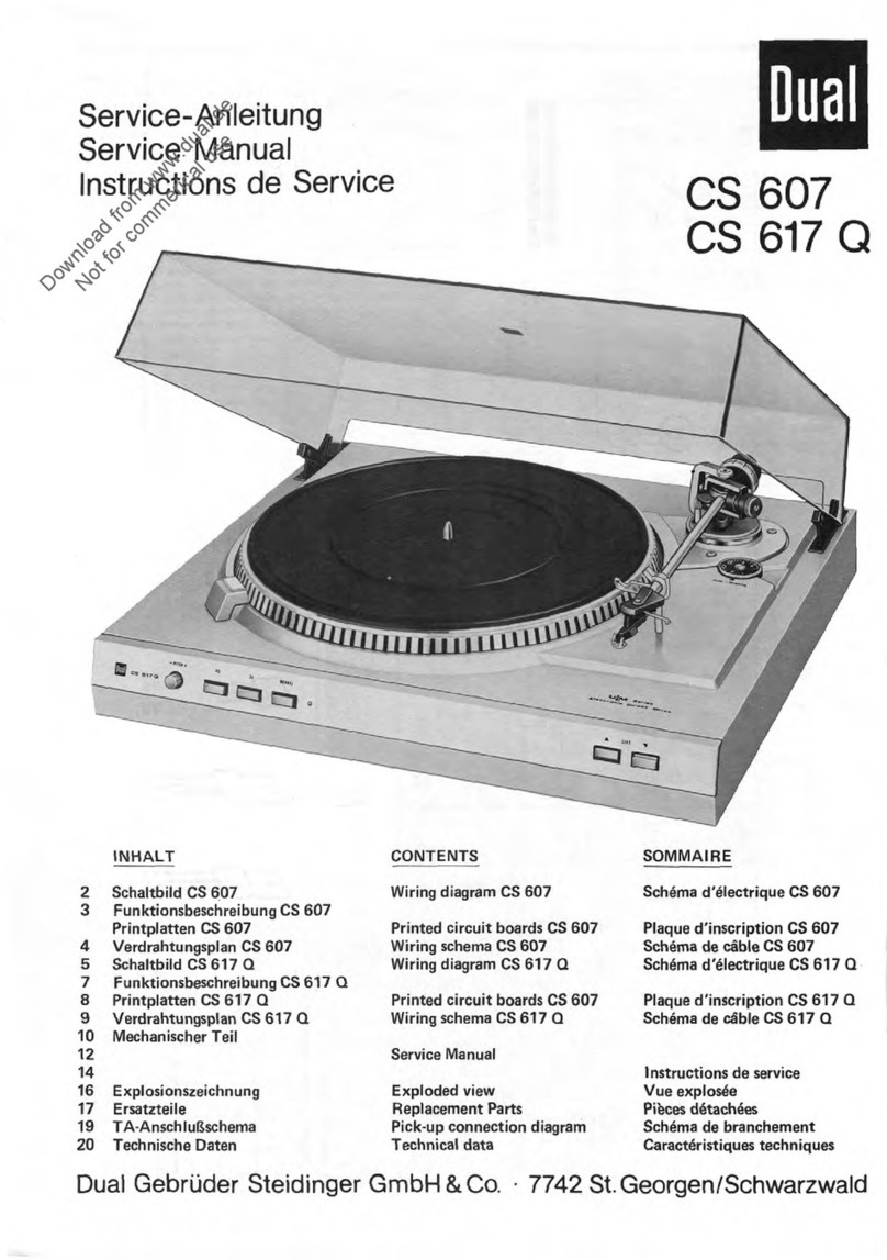
  9. Dual ASP 128 User manual

Dual ASP 128 User manual

Dual
Service
-Anleitung
Service
Manual
Instructions
de
Service
AS
P
128
Technische
Daten
Meßwerte
=
typische
Werte
Technical
data
Measured
values
=
typical
values
Caractöristiques
techniques
Valeurs
mesurees
=
vaieurs
typiq,es
Riemenantrieb
tacho-geregelter
Gleichstrommotor
Belt
drive
tacho-controlled
DC
motor
Entrainement
ä
courrole
moteur
ä
courant
continu
regle
par
tension
de
gänäratrice
Dual
DC
210-1
Betriebsspannung
Gleichstrom
Operating
voltage
DC
Tension
service
courant
continu
12
V
Stromaufnahme
bei
Anlauf
bei
Spielbetrieb
Power
consumption
at
start
at
play
Consommation
au
dämarrage
de
courant
en
fonctionnement
approx.
350
mA
approx.
50
mA
Plattenteller
-Drehzahlen
Platter
speeds
Vitesses
du
plateau
33
1/2
,
45
rpm
Plattenteller
nichtmagnetisch,
abnehmbar
Platter
non-magnetic,
removable
Plateau
ant
magnetique,
amovible
304
mm
0
verwindungssteifer
Alu
-Rohrtonarm
Distortion-free
aluminium
tubular
tonearm
Bras
en
tube
d'aluminium,
antitorsion
Magnet
-Tonabnehmer
HiFi
DIN
45500
rot
R
rechter
Kanal
grün
RG
rechter
Kanal
Masse
blau
GL
linker
Kanal
Masse
weiß
L
linker
Kanal
Cartridge
HiFi
DIN
45500
red
R
right
channel
green
RG
right
channel
ground
blue
GL
left
channel
ground
white
L
left
channel
Cellule
HiFi
DIN
45
500
rouge
R
canal
droit
vert
RG
masse
canal
droit
bleu
GL
masse
canal
gauche
blanc
L
canal
gauche
Dual
DMS
239
Diamantnadel
Diamond
stylus
Aigunietdiamant
Dual
DN
239
o
16,5
p.rn
Empfohlene
Auflagekraft
Tracking
force
Force
d'appui
25
mN
(20-30
mN)
Übertragungsbereich
Frequency
range
Bande
passante
20
Hz
—
20
kHz
Übertragungsfaktor
Output
Facteur
de
transmission
3,5
mV/5
cms
-1
/
1
kHz
Gleichlaufschwankungen
nach
DIN
Wow
and
flutter
(DIN)
Toleranz
de
vites
(DIN)
±
0,15%
Störspannungsabstand
(nach
DIN
45500)
Rumpel-Fremdspannungsabstand
Rumpel-Geräuschspannungsabstand
Signal-to-noise
ratio
(DIN
45500)
Rumble
unweighted
signal-to-noise
ratio
Rumble
weighted
signal-to-noise
ratio
Rapport
signal/bruit
(DIN
45500)
Signal/tension
exterieure
de
ronflement
Signal/tension
perturbatrice
de
ronflement
40
dB
63
dB
Effektive
Tonarmlänge
Effective
tonearm
length
Longueur
efficace
du
bras
211
mm
Kröpfungswinkel
Offset
angle
Angle
de
coude
26'
Überhang
Overhang
Excädent
19,5
mm
Tangentialer
Spurfehlwinkel
Tangential
tracking
error
Angle
tangentiel
de
l'erreur
de
piste
0,15°/cm
Rad.
Motor
und
Antrieb
Der
Antrieb
des
Plattentellers
und
der
Kinematik
erfolgt
durch
den
tachogeregel-
ten
Gleichstrommotor
Dual
DC
210-1.
Einstellen
der
Nenndrehzahlen
1
Steller
(Pitch)
in
Mittelstellung
bringen.
2
Drehzahlumschalter
in
Stellung
„45"
mit
R
9002
Nenndrehzahl
45
U/min
einstellen.
3
Drehzahlumschalter
in
Stellung
„33"
mit
R
9003
Nenndrehzahl
33
U/min
einstellen.
Reihenfolge
beachten!
Plattenteller
Der
Plattenteller
4
ist
mit
der
Tellersicherung
3
gesichert.
Zum
Abnehmen
des
Plattentellers
4
die
Tellersicherung
3
seitlich
abziehen.
Tonarm
und
Tonarmlagerung
Ausbau
des
Tonarmes
kpl.
mit
Tonarmlagerung
Es
empfiehlt
sich
wie
folgt
vorzugehen:
1.
Schraube
62
entfernen
und
Abdeckung
60
abnehmen.
2.
Haupthebel
26
abnehmen.
Sicherungsscheibe
78
entfernen.
Zugfeder
75
aushängen
und
Stellschiene
74
mit
Führungslager
77
sowie
Druckfeder
76
abnehmen.
3.
Hulse
58
abnehmen
und
Abstellschiene
20
aushängen.
4.
Tonarmleitungen
an
Anschlußplatte
11
ablöten.
Schraube
35
entfernen
und
Tonarm
55
abnehmen.
Der
Einbau
erfolgt
in
umgekehrter
Reihenfolge.
Austausch
des
Tonarmes
1.
Tonarm
55
verriegeln.
Gewicht
49
entfernen.
2.
Tonarmleitungen
an
Anschlußplatte
11
nlöten.
Dual
GmbH
•
Postfach
1144
•
7742
St.
Georgen/Schwarzwald
920
817
1.3/0883
Printed
in
Germany
by
Dual
Download from www.dual.de
Not for commerical use
3.
Sicherungsscheibe
50
an
der
Lagerspitze
52
entfernen.
Lager
54
gegen
die
gefederte
Lagerspitze
52
drücken,
so
daß
der
Tonarm
55
aus
dem
Lager-
rahmen
53
entnommen
werden
kann.
Der
Einbau
erfolgt
in
umgekehrter
Reihenfolge.
Tonarmlift
Austausch
des
Heberbolzens
1.
Haupthebel
26
abnehmen.
Sicherungsscheibe
78
entfernen.
Zugfeder
75
aushängen
und
Stellschiene
74
mit
Führungslager
77
sowie
Druckfeder
76
abnehmen.
2.
Steuerpimpel
33
abnehmen
und
Heberbolzen
36
austauschen.
Der
Einbau
erfolgt
in
umgekehrter
Reihenfolge.
Justagepunkte
Aufsetzpunkt
Drehzahlumschalter
in
Stellung
33.
Durch
Drehen
des
auf
der
Drehplatte
80
befindlichen
Exzenters
J
kann
der
Aufsetzpunkt
justiert
werden.
Die
Einstellung
ist
sowohl
für
17
-cm-
sowie
für
30
-cm
-Schallplatten
wirksam.
Der
Exzenter
ist
durch
eine
Öffnung
in
der
Abdeckung
60
zugänglich.
Abstellpunkt
Der
Abstellpunkt
(Abstellbereich
Platten
0
125-115
mm)
kann
durch
gering-
fügiges
Biegen
der
Abstellschiene
20
verändert
werden.
Tonarmlift
Die
Lifthöhe
läßt
sich
durch
Drehen
der
Schraube
32
verändern.
Der
Abstand
zwischen
Schallplatte
und
Abtastnadel
soll
ca.
5
mm
betragen.
Motor
and
Drive
Power
for
the
turntable
platter
and
the
changing
mechanism
is
supplied
by
a
tacho
controlled
DC
motor
Dual
DC
210-1.
Adjusting
the
rated
speed
1.
Set
the
control
(pitch)
in
central
position.
2.
Set
speed
control
switch
in
position
„45"
with
R
9002
adjust
the
rated
speed
45
U/min.
3.
Set
speed
control
switch
in
position
„33"
with
R
9003
adjust
the
rated
speed
33
U/min.
Note
succession!
Platter
The
platter
4
is
secured
with
the
locking
spring
3.
When
removing
the
platter
4
to
detach
the
locking
spring
side
ways
from
the
spindle.
Tonearm
and
tonearm
bearing
Dismantling
the
tonearm
complete
with
the
tonearm
bearing.
We
recommend
the
following
procedure:
1.
Remove
the
screw
62
and
cover
60.
2.
Remove
the
main
lever
26.
Remove
the
lock
washer
78.
Disengage
the
tension
spring
75
and
remove
the
positioning
rail
74
with
guide
bearing
77
and
compression
spring
76.
3.
Remove
the
sleeve
58
and
lift
the
shutt-off
rail
20.
4.
Unsolder
off
the
tonearm
connections
at
the
connection
board.
11.
Remove
the
screw
35
and
the
tonearm
55.
Reassembly
involves
the
reverse
procedure.
Changing
the
tonearm
1.
Lock
the
tonearm
55
in
rest
position.
Remove
the
weight
49.
2.
Unsolder
oft
the
tonearm
connections
at
the
connection
plate
11.
3.
Remove
the
locking
washer
50
an
the
Bearing
point
52.
Press
the
bearing
54
in
the
direction
of
the
spring
bearing
point
52,
so
that
the
tonearm
55
may
be
removed
from
the
front
of
the
bearing
frame
53.
For
reassembly
follow
the
reverse
procedure.
Cue
control
Changing
the
lift
bolt
1.
Remove
the
main
lever
26.
Remove
the
lock
washer
78.
Disengage
the
tension
spring
75
and
remove
the
positioning
rail
74
with
guide
bearing
77
and
compression
spring
76.
2.
Remove
the
pin
33
and
the
lift
bolt
36.
Reassembly
involves
the
reverse
procedure.
Adjustment
points
Set
down
point
Speed
lever
in
position
33.
The
set
down
point
of
the
tonearm
can
be
altered
with
the
excentric
bolt
J
(rotary
plate
80).
The
setting
is
effective
not
only
for
17
cm
but
also
for
30
cm
records.
The
excentric
bolt
J
is
accessible
through
the
hole
in
the
cover
60.
Switch
off
point
The
switch
oft
point
(switch
oft
range
record
0
125-115
mm)
can
be
adjusted
by
slight
bending
the
shutt-off
rail
20.
Tonearm
lift
The
lift
can
be
varied
by
turning
the
screw
32.
The
distance
between
the
record
and
the
needle
should
be
approx.
5
mm.
Moteur
et
entrainement
Le
plateau
et
la
cinernatique
sont
entraines
par
un
moteur
ä
courant
continu
regle
par
tension
generatrice
Dual
DC
210-1.
lieglage
la
vitesse
nominales
1.
Amener
le
regulateur
(Pitch)
en
position
mediane.
2.
Amener
le
commutateur
de
vitesse
ä
la
position
„45"
rägler
la
vitesse
de
45
tr/mn
avec
le
rägulateur
R
9002.
3.
Amener
le
commutateur
de
vitesse
ä
la
position
„33"
regier
la
vitesse
de
33
tr/mn
avec
le
rägulateur
R
9003.
Notifiez
la
suite!
Plateau
Le
plateau
est
fixe
par
le
ressort
de
protection
3.
Retirez
le
blocage
du
plateau
4
de
son
axe
parte
cöte
et
ötez
le
plateau.
Bras
de
lecture
et
suspension
Demontage
du
bras
II
est
conseille
de
proceder
comme
däcrit
ci-apräs:
1.
Enlever
vis
62
et
la
couverture
60.
2.
Retirer levier
principal
26.
Enlever
la
rondelle
securite
78.
Decrocher
le
ressort
de
traction
142.
Retrier
la
barre
de
räglage
74
et
le
palier
de
guidage
77
et
ressort
de
pression
76.
3.
Enlever
le
casse
58
et
barre
d'arret.
4.
Dessouder
les
cäbles
du
bras
sur
le
plaque
de
branchement
11.
Enlever
la
vis
35.
Pour
le
montage,
proceder
en
ordre
inverse.
Remplacement
du
bras
de
lecture
1.
Verrouiller
le
bras
de
lecture
55.
Enlever
le
contrepoids
49.
2.
Dessouder
les
cäbles
du
bras
sur
le
plaque
de
branchement
11.
3.
Enlever
l'anneau
de
retenue
50.
Pousser
le
palier
54
contre
la
pointe
elastique
de
support
52
de
teile
maniere
que
le
bras
de
lecture
55
puisse
etre
retire
du
cadre
de
support
53
par
l'avant.
Pour
le
montage,
procäder
en
ordre
inverse.
Löve-bras
Remplacement
de
la
tube
du
leve-bras
1.
Retirer
le
levier
principal
26.
Enlever
la
rondelle
securite
78.
Deorocher
le
ressort
de
traction
75.
Retrier
la
barre
de
räglage
74
et
le
palier
de
guidage
77
et
ressort
de
Pression
76.
2.
Retirer
le
pilon
de
guidage
33
et
remplacement
de
la
tube
du
läve-bras
36.
Pour
le
montage,
proceder
en
ordre
inverse.
Points
d'ajustage
Point
de
pose
du
bras
Le
commutateur
de
vitesse
ä
la
position
33.
Le
point
de
pose
du
bras
peut
etre
modifie
a
l'aide
du
boulon
excentrique
J
plaque
rotative
80.
Le
reglage
est
valable
aussi
bien
pour
les
disques
de
17
cm
que
pour
les
disques
de
30
cm.
Le
boulon
excentrique
J
est
accessible
par
le
trou
mänage
sur
le
coverture
60.
Point
d'arrät
II
est
possible
de
fair
varier
le
point
d'arrät
interieur
de
la
zone
prevue
ä
cet
effet
(Ode
disque
de
125-115
mm).
Procäder
ä
l'ajustage
en
tordant
le
barre
d'arrät
20.
Leve-bras
La
distance
entre
le
disque
et
la
pointe
de
lecture
peut
etre
reglee
ä
l'aide
de
la
vis
32.
elle
doit
etre
d'env.
5
mm.
Explosionszeichnung
/
Exploded
view
/
Vue
explostee
0-
0
<-)
e
--
e-
Ersatzteile
•
Replacement
parts
•
Pieces
datachee
•
ASP
128
Pos.
Art.-Nr.
Stck
Bezeichnung
1
220
212
1
Zentrierstück
2
274
787
1
Plattentellerbelag
3
274
788
1
Plattenteller
4
270
557
1
Sicherung
6
272
489
1
Flachriemen
7
273
388
1
Antriebsteller
9
271
780
1
Motorbefestigungsteile
11
272
136
1
Anschlußplatte
5-polig
12
275
193
1
Grundplatte
14
273
466
1
Aufnahmetopf
mit
Gummipuffer
17
272
110
1
PT-Schraube
18
272
111
1
Distanzstück
19
273
580
1
Zugfeder
20
272074
1
Abstellschiene
21
209
358
1
Kugel
,
22
272
081
1
Startschieber
23
273
390
1
Kurvenrad
24
272
079
1
Lagerbock
25
210
148
1
Sicherungsscheibe
5
26
273
391
1
Haupthebel
27
209
358
1
Kugel
28
273
144
1
Druckfeder
29
273
136
1
Skatingring
30
262
864
1
Lagerspitze
31
272
068
1
Druckfeder
32
272
119
1
Zylinderschraube
M
3
x
6
33
237
660
1
Steuerpimpel
34
273
138
1
Tonarmsockel
35
272
070
1
PT-Schraube
3
x
12
36
274
781
1
Heberbolzen
37
272
450
1
Druckfeder
38
274
791
1
Segment
39
272
073
1
PT-Schraube
3
x
20
40
274
789
1
DC-Motor
210-1
kpl.
41
272
062
1
Klinke
42
272
055
1
Schaltarm
43
226
895
1
Scheibe
5,1/10/0,75
44
272
438
1
Kugel
05
45
234
303
1
Druckfeder
46
272
057
1
Umschaltwinkel
Zum
Motor
DC
210
-
1
PITCH
R900!
R9002
R9005
5C53
n45
22K
560
si
33
R9003
R9004
n33
2,2K
270
Verdrahtungsplan
/
Wir
i
ng
schema
/
Sch
äma
de
cäble
Si
=
Drehzahlschalter/Speed
selector
switch
S2
=
Motorschalter/Motor
switch
+
12
V
z.
Motor
I
.zum
Motor
n4e
-,
1
Pos.
Art.-Nr.
Stck
Bezeichnung
47
272
848
1
Mikroschalter
48
210
147
1
Sicherungsscheibe
4
49
274
794
1
Gewicht
kpl.
50
210
145
1
Sicherungsscheibe
2,3
51
229
685
1
Druckfeder
52
262
864
1
Lagerspitze
53
275
195
1
Lagerrahmen
kpl.
54
275
196
1
Lager
kpl.
55
274
793
1
Tonarm
kpl.
56
273
397
1
Tonarmkopf
kpl.
57
266
862
1
Zylinderschraube
M
2,5
x
8
58
272
839
1
Hülse
59
272
125
1
Tonarmstütze
60
274
790
1
Abdeckung
kpl.
61
272
454
1
Lifthebel
62
218
055
1
Linsenblechschraube
2,9
x
9,5
4
r
im
272
084
1
Drehzahlumschaltknopf
64
272
107
1
Pitchknopf
67
272
372
1
Umschaltgabel
68
272
373
1
Schenkelfeder
70
272
439
1
Schaltschiene
71
272
455
1
Schalthebel
74
273
700
1
Stellschiene
75
249
076
1
Zugfeder
76
235
150
1
Druckfeder
77
239
934
1
Führungslager
78
210
146
1
Sicherungsscheibe
80
270
845
1
Drehplatte
81
210
146
1
Sicherungsscheibe
82
272
077
1
Zugfeder
83
272
818
1
Skatinghebel
84
273
135
1
Zugfeder
86
272
374
1
Halteplatte
87
272
371
1
Reglerplatte
kpl.
R
9001
272
393
1
500
Ohm
lin.
R
9002
263
588
2
Steller
2,2
kOhm
R
9003
263
588
2
Steller
2,2
kOhm
S
9001
272
392
1
Federsatz
272
843
1
Bedienungs-Anleitung
Anschlußplatte
5-polig
Connecting
plate
5-pin
Plaque
de
branchement
5-pöles
Änderungen
vorbehalten!
Subject
to
change!
Sous
raserve
de
modification!
weiß
I.K
grün
schwarz
GN
D
blau
+1(3

Other Dual Speakers manuals

Dual CST 100 User manual

Dual

Dual CST 100 User manual

Dual LU47PB Operating instructions

Dual

Dual LU47PB Operating instructions

Dual SBX6502 User manual

Dual

Dual SBX6502 User manual

Dual DMP672 User manual

Dual

Dual DMP672 User manual

Dual LU43PB Operating instructions

Dual

Dual LU43PB Operating instructions

Dual DMP670 Operating instructions

Dual

Dual DMP670 Operating instructions

Dual DC265 Operating instructions

Dual

Dual DC265 Operating instructions

Dual MARINE DMP66 Operating instructions

Dual

Dual MARINE DMP66 Operating instructions

Dual LUR652E Operating instructions

Dual

Dual LUR652E Operating instructions

Dual DMP670 User manual

Dual

Dual DMP670 User manual

Dual LU48BTS User manual

Dual

Dual LU48BTS User manual

Dual LU Series Operating instructions

Dual

Dual LU Series Operating instructions

Dual LUR66E Operating instructions

Dual

Dual LUR66E Operating instructions

Dual DC265W Operating instructions

Dual

Dual DC265W Operating instructions

Dual CS 505-1 User manual

Dual

Dual CS 505-1 User manual

Dual CS 607 User manual

Dual

Dual CS 607 User manual

Dual 622 User manual

Dual

Dual 622 User manual

Dual DMP670 User manual

Dual

Dual DMP670 User manual

Dual DMS652 Operating instructions

Dual

Dual DMS652 Operating instructions

Dual DMS651 Operating instructions

Dual

Dual DMS651 Operating instructions

Dual LS205EB Operating instructions

Dual

Dual LS205EB Operating instructions

Dual DMP66 Operating instructions

Dual

Dual DMP66 Operating instructions

Dual L83BK Operating instructions

Dual

Dual L83BK Operating instructions

Popular Speakers manuals by other brands

Manta SPK417 user manual

Manta

Manta SPK417 user manual

EarthQuake EQ6C4 Specifications

EarthQuake

EarthQuake EQ6C4 Specifications

ABK WL322N user manual

ABK

ABK WL322N user manual

Braven 650 owner's guide

Braven

Braven 650 owner's guide

LOTRONIC ibiza SOUND FREESOUND40-BK instruction manual

LOTRONIC

LOTRONIC ibiza SOUND FREESOUND40-BK instruction manual

Sonance Merlot 421MR instruction manual

Sonance

Sonance Merlot 421MR instruction manual

THOMSON WS02 Series operating instructions

THOMSON

THOMSON WS02 Series operating instructions

Njoy MS-R201 user manual

Njoy

Njoy MS-R201 user manual

Eltax Monitor Series user manual

Eltax

Eltax Monitor Series user manual

DLS MR5 owner's manual

DLS

DLS MR5 owner's manual

AUDAC CS55 User manual & installation guide

AUDAC

AUDAC CS55 User manual & installation guide

Ultimate Ears BOOM 3 Get started

Ultimate Ears

Ultimate Ears BOOM 3 Get started

Xiamen Huipeng Import&Export DYE-BL1-TY1-2 instruction manual

Xiamen Huipeng Import&Export

Xiamen Huipeng Import&Export DYE-BL1-TY1-2 instruction manual

JL Audio C2-075ct owner's manual

JL Audio

JL Audio C2-075ct owner's manual

Sony SRS-RA5000 Service manual

Sony

Sony SRS-RA5000 Service manual

Bose FreeSpace DS 40SE installation guide

Bose

Bose FreeSpace DS 40SE installation guide

Sony SRS-XV900 reference guide

Sony

Sony SRS-XV900 reference guide

Toa CS-154U instruction manual

Toa

Toa CS-154U instruction manual

manuals.online logo
manuals.online logoBrands
  • About & Mission
  • Contact us
  • Privacy Policy
  • Terms and Conditions

Copyright 2025 Manuals.Online. All Rights Reserved.