Emergency Lighting Fluorescent Battery Pack
IMPORTANT SAFEGUARDS
When using electrical equipment, basic safety precautions should
always be followed including the following.
READ AND FOLLOW ALL SAFETY
INSTRUCTIONS
1. To prevent high voltage from being present on red & yellow output leads prior to installation, inverter
connector must be open. Do not join inverter connections until installation is complete and AC power is
supplied to the emergency ballast.
2. This product is for use with most 32 W through 40 W T8, T10, or T12 single pin or bipin uorescent lamps,
including energy saving, circline, U-shaped and rapid-start (4-pin) long compact uorescent lamps.
3. Make sure all connections are in accordance with the National Electrical Code and any local regulations.
4. To reduce the risk of electrical shock, disconnect both normal and emergency power supplies and inverter
connector of the emergency ballast before servicing.
5. This emergency ballast is for factory or eld installation in either the ballast channel or on top of the xture.
6. This product is suitable for damp locations where the ambient temperature is 0°C minimum, +55°C
maximum. Product is not suitable for heated air outlets and wet or hazardous locations.
7. An unswitched AC power source is required (120 through 277 VAC, 60 Hz).
8. Do not install near gas or electric heater.
9. Do not attempt to service the battery. A sealed, no-maintenance battery is used that is not eld replaceable.
Contact the manufacturer for information on service.
10. The use of accessory equipment not recommended by the manufacturer may cause an unsafe condition.
11. Do not use this product for other than intended use.
12. Servicing should be performed by qualied service personnel.
CAUTION: Verify that all replacement lamp types marked on the installed luminaire are also identied as suitable for use
with this inverter/charger pack.
SAVE THESE INSTRUCTIONS
WARNING - This product contains chemicals known to the State of California to cause cancer,
birth defects, and/or other reproductive harm. Thoroughly wash hands after installing, cleaning, or
otherwise touching this product.
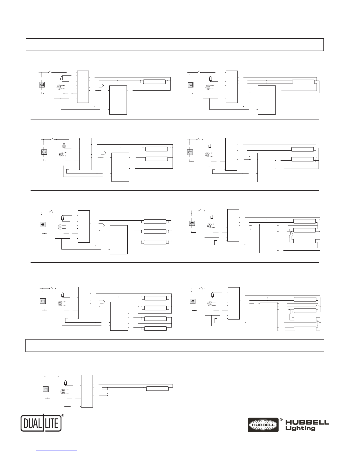
UFO-3AW
INSTALLATION INSTRUCTIONS
INSTALLATION INSTRUCTIONS - Auto Select
! IMPORTANT SAFEGUARDS !
WHEN USING ELECTRICAL EQUIPMENT, BASIC SAFETY PRECAUTIONS SHOULD ALWAYS BE
FOLLOWED, INCLUDING THE FOLLOWING:
READ AND FOLLOW ALL SAFETY INSTRUCTIONS
1. To prevent high voltage from being present on red & yellow output leads prior to installation,
inverter connector must be open. Do not join inverter connector until installation is complete and
AC power is supplied to the emergency ballast.
2. This product is for use with 16 W through 40 W (2ft - 4ft) T8 and T12 single pin or bipin for one
or two lamp emergency mode operation, instant start and rapid start; 40 W through 215 W (5ft -
8ft) T8 and T12 single pin or bipin for one lamp emergency mode operation, instant start and
rapid start; and 16 W through 31 W U-Bend T8 bipin for one or two lamp emergency mode
operation, instant start and rapid start flourescent lamp fixure
3. Make sure all connections are in accordance with the National Electrical Code and any local
regulations.
4. To reduce the risk of electric shock, disconnect both normal and emergency power supplies and
inverter connector of the emergency ballast before servicing.
5. This emergency ballast is for factory or field installation in either the ballast channel or on top of
the fixture.
6. This product is suitable for damp locations where the ambient temperature is 0°C minimum,
+50°C maximum. Product is also suitable for installation in sealed and gasketed fixtures. Product
is not suitable for heated air outlets and wet or hazardous locations.
7. An unswitched AC power source is required (120 through 277 VAC, 50/60 Hz).
8. Do not install near gas or electric heaters.
9. Do not attempt to service the battery. A sealed, no-maintenance battery is used that is not field
replaceable. Contact the manufacturer for information on service.
10. The use of accessory equipment not recommended by the manufacturer may cause an unsafe
condition.
11. Do not use this product for other than intended use.
12. Servicing should be performed by qualified service personnel.
CAUTION: Verify that all replacement lamp types marked on the installed luminaire are also identified
as suitable for use with this inverter/charger pack.
SAVE THESE INSTRUCTIONS
UFO-6W
Ni - Cd
CONTAINS NICKEL-CADMIUM
RECHARGEABLE BATTERY.
MUST BE RECYCLED OR
DISPOSED OF PROPERLY.
©
Hubbell Lighting, Inc. • 701 Millennium Blvd • Greenville, SC 29607 • (864) 678-1000 • FAX (864) 678-1415 • www.dual-lite.com
93063952
WARNING – This product contains chemicals known to the State of California to cause cancer, birth defects and/or other
reproductive harm. Thoroughly wash hands after installing, handling, cleaning, or otherwise touching this product.
09/17/15
B
2 1
2 1
A
B
A
SGHMDBEC-091027001
11.OCT.2010
B
REV DATE RECORD DESN CHCK
SHT 1
1 SHTS
N/A N/A
130X002
SEE NOTE
UNDER ART
C
ARTWORK-LOGO UL
SGH 10/11/10
SGH 10/11/10
---
SGH 10/11/10
DRAWING NO.SIZE
A
SCALE
CATALOG NO.
ENGINEERING:
CHECKED BY:
DIMENSIONS IN INCHES
DIMENSIONS IN [ ] IN MM
CONFORMS TO ASME Y14.5M
DO NOT SCALE PRINT
DRAWN:
THIRD ANGLE PROJECTION
MATERIAL: FINISH: PART NO.
REV.
CRITICAL DIMENSIONS
This document contains confidential and proprietary information of Dual Lite.
Receipt or possession of this document does not convey any rights to
reproduce or disclose its contents, or to make, use , or sell anything it may
disclose. Reproduction, disclosure, or use of the document or its contents,
without the specific written authorization of Dual Lite, may violate the
intellectual property rights of Dual Lite.
UNSPECIFED TOLERANCES: INCHES
X.X=±0.1 X.XX=±0.03 X.XXX=±0.010
FRACTIONS=±1/32 ANGULAR TOLERANCE=±1°
NONE
JEBJEBEC-160616002
16.JUN.2016
C
NO LISTING
UL LOGO
ARTWORK
P/N 1300827
56B5 LISTING
UL LOGO
ARTWORK
P/N 1300828
EMERGENCY
LIGHTING
EQUIPMENT
56B5
57B9 LISTING
UL LOGO
ARTWORK
P/N 1300842
EXIT FIXTURE
57B9