DualLite UFO-RP3 User manual

UFO-RP3
FLUORESCENT BATTERY PACK
CONTAINS NICKEL-CADMIUM
RECHARGEABLE BATTERY.
MUST BE RECYCLED OR
DISPOSED OF PROPERLY. Ni - Cd
LISTED
UL
R
93039247-A
Warning-This product contains chemicals known to the State of California to cause cancer, birth
defects and/or other reproductive harm. Thoroughly wash hands after installing, handling, cleaning,
or otherwise touching this product.
Page 1
Hubbell lighting, Inc,• 701 Millennium Blvd.Greenville SC 29607•864 678-1000•FAX (864) 678-1415•www.dual-lite.com
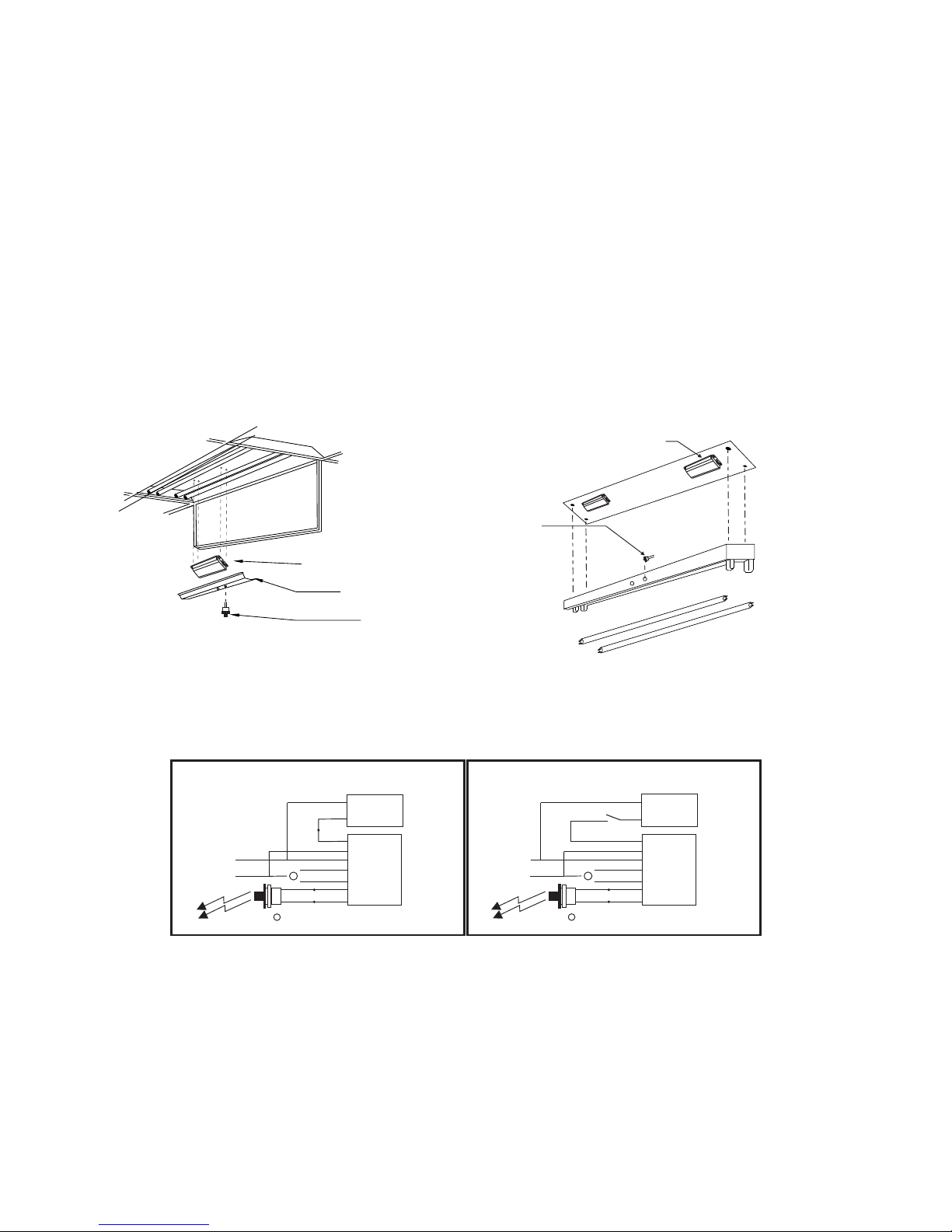
1. - To prevent electrical shock, do not mate unit connector until installation is complete andCAUTION
power is supplied to the unit.A.C.
3. The battery is sealed, non-maintenance, and is not replaceable in the field. Please contact manu-
facturer for information on service. Do not attempt to service the battery please.
4. . The product is for use with grounded, UL Listed, indoor fixtures except in
heated air outlets or hazardous locations.
DO NOT USE OUTDOORS
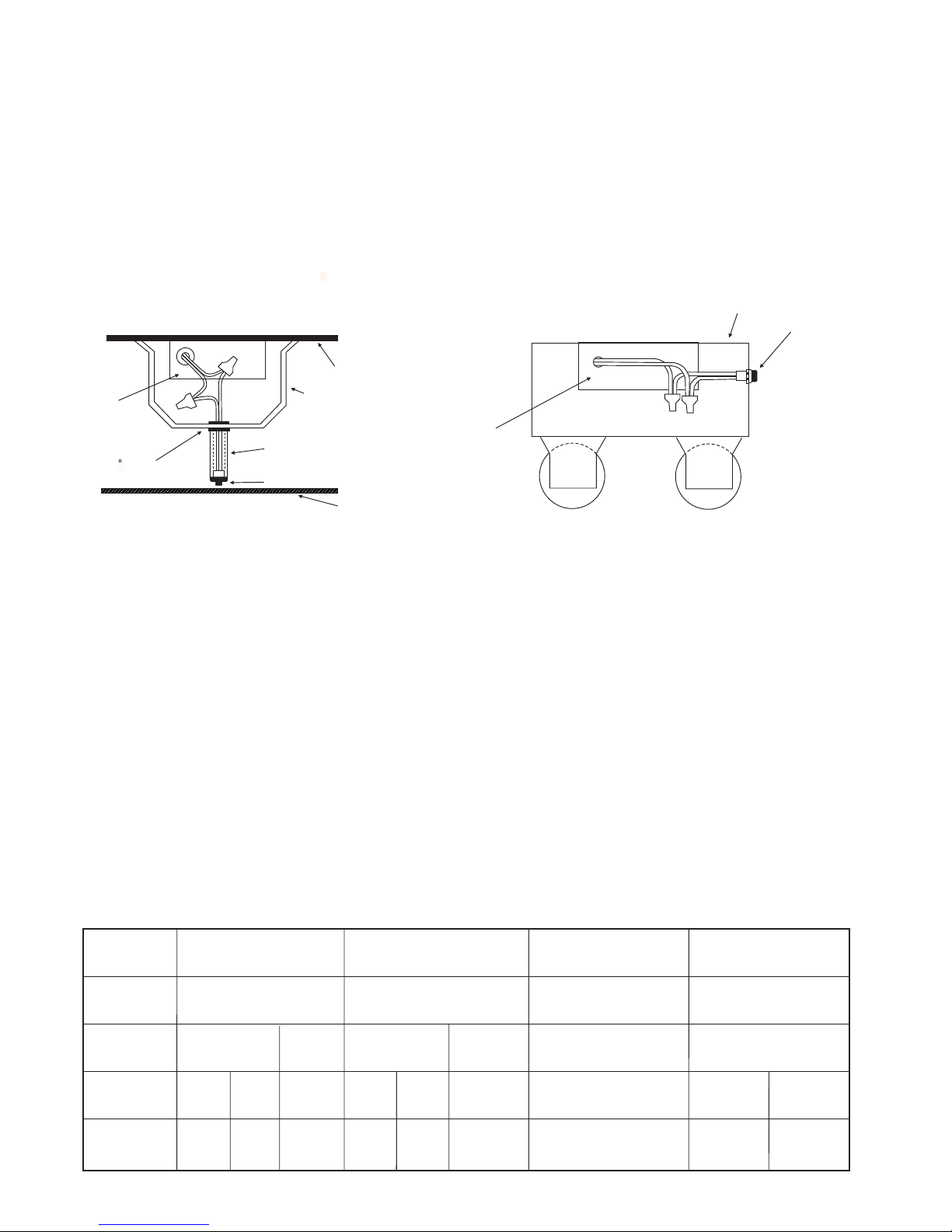
5. The product requires an unswitched A.C. Power source of either 120 or 277 volts. Properly cap the
unused A.C. Lead.
6. Do not mount near gas or electric heaters.
7. The product should be mounted in locations and at heights where it will not readily be subjected to tam-
pering by unauthorized personnel.
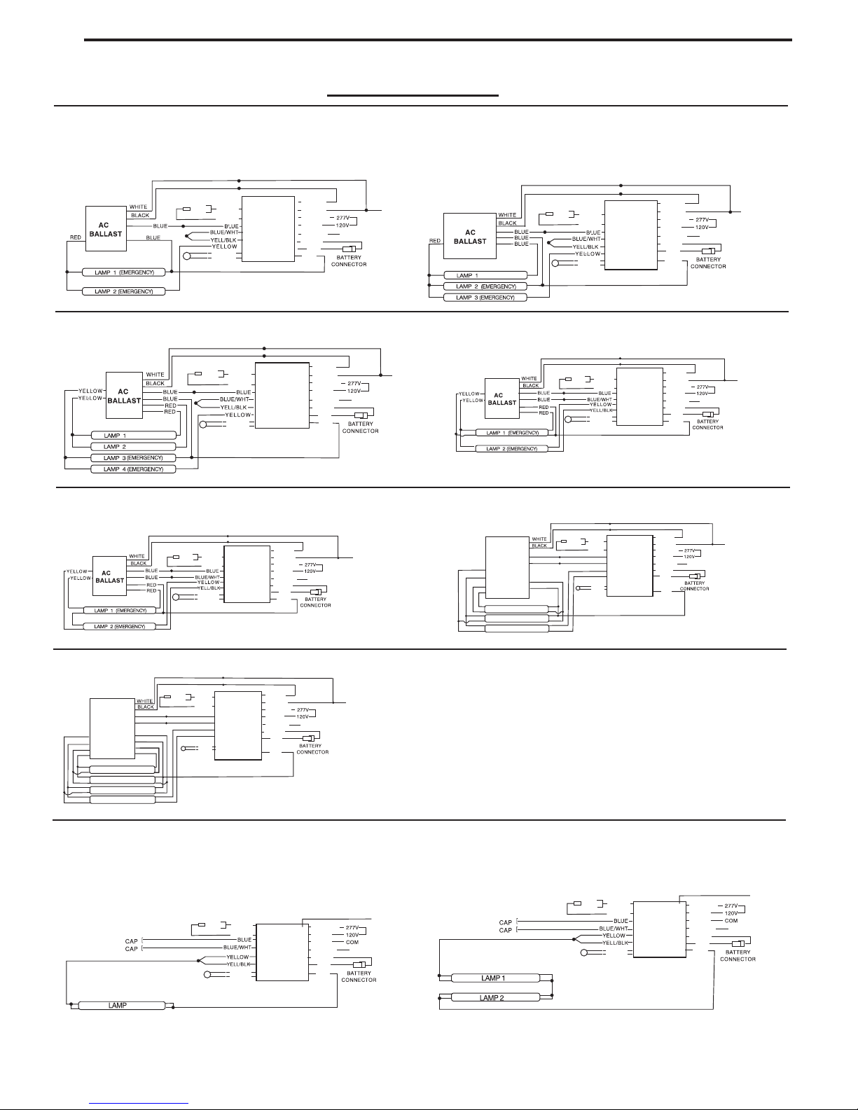
9. The product is compatible with all A.C. magnetic and electronic ballasts including multiple lamp ballasts
with one lamp operating in the emergency mode.
IMPORTANT SAFEGUARDS
When using electrical equipment, basic safety precautions should always be followed, including the following:
READ AND FOLLOW ALL SAFETY INSTRUCTIONS
SAVE THESE INSTRUCTIONS
2. - This fixture provides more than one power supply output source. To reduce the risk of
electrical shock, disconnect both normal and emergency sources by turning off the A.C. Branch circuit
and by disconnecting the unit connector.
CAUTION
10. The use of accessory equipment not recommended by the manufacturer may cause an unsafe condition.
11. Do not use this equipment for other than intended use.
12. Install in accordance with the National Electrical Code and local regulations.
13. Installation and servicing should be performed by qualified personnel.
14. Lighting fixture manufacturers, electricians and end users need to ensure product system compatibility
before final installation.
15. The battery is sealed,non-maintenance,and is not replaceable in the field. Please contact
manufacturer for information on service. Do not attempt to service the battery please.
16. The rated operating time in the emergency mode with battery is 1-1/2 hours and the recharge
time shall not be less than 24 hours.
8. This product is for use with 14 W through 54W(2'-4')T5 and T8 single pin or bipin for one lamp,Instant
Start,14W through 39W(2'-4')T5 and T8 singleStart and Rapid pin or bipin for two lamp, Instant Start and
through 50 W (4-pin)Rapid Start, 18W long compact Rapid Start, or 32 W (4-pin) compact, 24W through
fluorescent lamps from Philips,Osram and GE or equivalent manufacture.32W U-Bend FBT8

NOTE: All the branch circuit wiring has to be ready as well as an unswitched source of power before the
fixture is installed. From the same branch circuit.Both AC and Emergency Ballasts must be Fed
CAUTION Battery connector has to be opened to prevent high voltage on output leads (Red and Yellow).
Wait until all power to the emergency ballastthe installation process is completed and AC is supplying
1. AC power has to be off before installation.
2. Choose the right wiring diagram to connect the emergency ballast to AC ballast and lamp.
3. Please ensure the electrical connections conform to the National Electrical Code and local regulations if applicable.
4. Follow the diagram 1&2 to install the emergency ballast in the ballast channel.
5. Wall switch has to be connected properly (Check diagram 3), Match the violet and brown leads to connect the to theTBIL
The would be onTBILemergency ballast(Check diagram 4). after the fixture is installed properly.
DIAGRAM 1 DIAGRAM 2
UFO-RP3
DIAGRAM 3
UNSWITCHED
FIXTURE
SWITCHED
FIXTURE
BLACK
HOT A.C. LINE
COMMON
TBIL
WHITE
WHT/BLK
WHITE
(277V) ORG
(120V) BLK
1
1
WHT
+ RED
A C BALLAST..
Select proper voltage lead. Cap unused lead.
BROWN
VIOLET
WHT/RED
BLACK
HOT A.C. LINE
COMMON
TBIL
WHITE
WHT/BLK
WHITE
(277V) ORG
(120V) BLK
1
1
WHT
+ RED
A C BALLAST..
Select proper voltage lead. Cap unused lead.
BROWN
VIOLET
WHT/RED
UFO-RP3
6.Please search in readily visible location and stick the label with CAUTION: This Unit Has More Than One Power Supply“
To Reduce The Risk Of ElectricConnection Point. Shock, Disconnect Both The Branch Circuit-Breakers Or Fuses And Emergency
Power Supplies Before Servicing.”
8. The battery needs to be charged for one hour in order to have short-term testing on the emergency function. Before having a
emergency function testing,long-term the battery in emergency ballast has to be charged for 24 hours.
7. Do not join the inverter connector until the fixture is completely installed and AC power is supplied to the emergency ballast.
NOTE: MARK AN APPROPRIATE LABEL ON INDICATOR LIGHT AND
TEST SWITCH AFTE INSTALLATION.
Page 2
Emergency Ballast
Ballast Channel Cover
Test Button,Indicator Light(TBIL)
Emergency Ballast
INSTALLATION INSTRUCTIONS
before joining the battery connector.

OPERATION
THIS EMERGENCY BALLAST WOULD FUNCTION AND OPERATE ONE OR TWO LAMPS
AT LEAST 90 MINUTES WHEN THE AC POWER IS FAILED.
THE EMERGENCY BALLAST WILL OPERATE 14WATT TO 54WATT LAMPS AT LEAST 90
MAINTENANCE
Illustration 1
Recessed Troffer Fixture
UFO-RP3
7 8 BUSHING/
FIXTURE
BALLAST CHANNEL COVER
PLASTIC TUBE
FIXTURE LENS
TBIL
Illustration 2
Strip Fixture
OBSERVE PROPER POLARITY
FIXTURE
TBIL
UFO-RP3
THE CHARGING INDICATOR LIGHT WOULD BE ON TO INDICATE THE BATTERY IS BEING
CHARGED WHEN AC POWER IS APPLIED.
NOTE: MARK AN APPROPRIATE LABEL ON INDICATOR LIGHT AND TEST SWITCH AFTER INSTALLATION.
NOTE: SERVICES SHOULD ONLY PERFORMED BY QUALIFIED PERSONNEL.
THE EMERGENCY BALLAST SHOULD BE CHECKED PERIODICALLY TO CONFIRM
AND THE FOLLOWINGFUNCTIONING SCHEDULE IS RECOMMENDED.
1) INSPECT THE CHARGING INDICATOR EVERY MONTH AND CONFIRM THAT IS
2) PUSH THE TEST SWITCH FOR 30 SECONDS TO ENSURE THE EMERGENCY BALLAST
PERFORM THIS TESTIS FUNCTIONING. EVERY 30 DAYS.
3) PERFORMING A LONG-TERM TEST (90 MINUTE BATTERY DISCHARGE) ONCE IN
ONE OR TWO LAMPSEVERY YEAR. SHOULD BE OPERATED FOR NO LESS THAN
1
NUMBER OF
LAMPS EMER.
POWER
(LENGTH)
BROWN
CONNECTOR CLOSE
2
OPEN OPEN
1
CLOSE
11
2
CLOSE CLOSE
24-32W
32W
1
CLOSE
1
14W-39W 40W-54W 18W-39W 40W-50W
OPEN
22
CLOSE
TABLE 1 (FOR BROWN CONNETOR)
LAMP
DIAMETER
BASE TYPE
T5 ,T8
SINGLE OR BIPIN
LONG COMPACT COMPACT
4 PIN(2G11) 4-PIN
U-Bend FBT8
4 PIN
Page 3
MINUTES.
ILLUMINATED.
90 MINUTES.

WIRING DIAGRAM
EMERGENCY BALLAST AND AC BALLAST MUST BE FED FROM THE SAME BRANCH CIRCUIT
NOTE: Use the proper input voltage lead, cap unused lead
For One Lamp Emergency Operation(14-54W)
B. T O (2) LAMP INSTANT START BALLAST
A. ONE (1) LAMP INSTANT START BALLAST
C. THREE (3) LAMP INSTANT START BALLAST D. FOUR (4) LAMP INSTANT START BALLAST
RED
BROWN
WARNING
BROWN
WHITE
WHT/BLK
ORANGE
BLACK
TO UNSWITCHED AC
USE PROPER TAP
CAP UNUSED LEAD
RED
WHITE
WHT/RED
COM
SWITCHED OR
UNSWITCHED
LINE
VIOLET(+)
BROWN(-)
RED
WHT
TBIL
Refer to Diagram 3 before connectingRefer to Diagram 3 before connecting
Refer to Table 1 before connecting
RED
BROWN
BROWN
WARNING WHITE
WHT/BLK
ORANGE
BLACK
TO UNSWITCHED AC
USE PROPER TAP
CAP UNUSED LEAD
RED
WHITE
WHT/RED
COM
SWITCHED OR
UNSWITCHED
LINE
VIOLET(+)
BROWN(-)
RED
WHT
TBIL
Refer to Diagram 3 before connecting
Refer to Table 1 before connecting
ORANGE
BLACK
TO UNSWITCHED AC
USE PROPER TAP
CAP UNUSED LEAD
RED
BROWN
BROWN
WARNING WHITE
WHT/BLK
RED
WHITE
WHT/RED
COM
SWITCHED OR
UNSWITCHED
LINE
VIOLET(+)
BROWN(-)
RED
WHT
TBIL
Refer to Diagram 3 before connecting
Refer to Table 1 before connecting
RED
BROWN
BROWN
WARNING WHITE
WHT/BLK
RED
WHITE
WHT/RED
COM
VIOLET(+)
BROWN(-)
RED
WHT
TBIL
SWITCHED OR
UNSWITCHED
LINE
ORANGE
BLACK
TO UNSWITCHED AC
USE PROPER TAP
CAP UNUSED LEAD
Refer to Diagram 3 before connecting
Refer to Table 1 before connecting
Typical schematics only may be used other ballast, consult the factory wiring diagram
E. ONE (1) LAMP RAPID START BALLAST
WHITE
WHT/BLK
ORANGE
BLACK
TO UNSWITCHED AC
USE PROPER TAP
CAP UNUSED LEAD
RED
WHITE
WHT/RED
COM
SWITCHED OR
UNSWITCHED
LINE
VIOLET(+)
BROWN(-)
RED
WHT
TBIL
Refer to Diagram 3 before connecting
Refer to Table 1 before connecting
F. T O (2) LAMP RAPID START BALLAST
RED
BROWN
WARNING
BROWN
WHITE
WHT/BLK
ORANGE
BLACK
TO UNSWITCHED AC
USE PROPER TAP
CAP UNUSED LEAD
RED
WHITE
WHT/RED
COM
SWITCHED OR
UNSWITCHED
LINE
VIOLET(+)
BROWN(-)
RED
WHT
TBIL
Refer to Diagram 3 before connectingRefer to Diagram 3 before connecting
Refer to Table 1 before connecting
G. T O (2) LAMP RAPID START BALLAST
RED
BROWN
WARNING
BROWN
WHITE
WHT/BLK
ORANGE
BLACK
TO UNSWITCHED AC
USE PROPER TAP
CAP UNUSED LEAD
RED
WHITE
WHT/RED
COM
SWITCHED OR
UNSWITCHED
LINE
VIOLET(+)
BROWN(-)
RED
WHT
TBIL
Refer to Diagram 3 before connecting
Refer to Table 1 before connecting
H.THREE (3) LAMP RAPID START BALLAST
BLUE BLUE
BLUE/WHITE
YELLOW
RED
LAMP 1
LAMP 2
AC
BALLAST
LAMP 3(EMERGENCY)
YELL/BLK
RED
BLUE
YELLOW
YELLOW
RED
BLUE/WHITE
BLUE/WHITE
BROWN
BROWN
WARNING
WHITE
WHT/BLK
ORANGE
BLACK
TO UNSWITCHED AC
USE PROPER TAP
CAP UNUSED LEAD
RED
WHITE
WHT/RED
COM
Refer to Diagram 3 before connectingRefer to Diagram 3 before connecting
SWITCHED OR
UNSWITCHED
LINE
VIOLET(+)
BROWN(-)
RED
WHT
TBIL
Refer to Table 1 before connecting
I.FOUR (4) LAMP RAPID START BALLAST
BLUE
BLUE/WHITE
YELLOW
LAMP 1
LAMP 3
AC
BALLAST
LAMP 4(EMERGENCY)
YELL/BLK
RED
LAMP 2
YELLOW
YELLOW
RED
RED
BLUE
BLUE
BROWN
BROWN
BLUE/WHITE
BLUE/WHITE
BROWN
BROWN
WARNING
WHITE
WHT/BLK
ORANGE
BLACK
TO UNSWITCHED AC
USE PROPER TAP
CAP UNUSED LEAD
RED
WHITE
WHT/RED
COM
Refer to Diagram 3 before connecting
SWITCHED OR
UNSWITCHED
LINE
VIOLET(+)
BROWN(-)
RED
WHT
TBIL
Refer to Table 1 before connecting
Page 4
RED
UFO-RP3 UFO-RP3
UFO-RP3 UFO-RP3
UFO-RP3
UFO-RP3
UFO-RP3
UFO-RP3
UFO-RP3

A. T O (2) LAMP INSTANT START BALLAST
BROWN
BROWN
WARNING
RED
WHITE
WHT/BLK
ORANGE
BLACK
TO UNSWITCHED AC
USE PROPER TAP
CAP UNUSED LEAD
RED
WHITE
WHT/RED
COM
SWITCHED OR
UNSWITCHED
LINE
VIOLET(+)
BROWN(-)
RED
WHT
TBIL
Refer to Diagram 3 before connecting
B. THREE (3) LAMP INSTANT START BALLAST
RED
BROWN
BROWN
WARNING WHITE
WHT/BLK
ORANGE
BLACK
TO UNSWITCHED AC
USE PROPER TAP
CAP UNUSED LEAD
RED
WHITE
WHT/RED
COM
SWITCHED OR
UNSWITCHED
LINE
VIOLET(+)
BROWN(-)
RED
WHT
TBIL
Refer to Diagram 3 before connectingRefer to Diagram 3 before connecting
Refer to Table 1 before connecting
WIRING DIAGRAM
EMERGENCY BALLAST AND AC BALLAST MUST BE FED FROM THE SAME BRANCH CIRCUIT
C. FOUR (4) LAMP INSTANT START BALLAST
BROWN
WARNING
BROWN
RED
WHITE
WHT/BLK
ORANGE
BLACK
TO UNSWITCHED AC
USE PROPER TAP
CAP UNUSED LEAD
RED
WHITE
WHT/RED
COM
SWITCHED OR
UNSWITCHED
LINE
VIOLET(+)
BROWN(-)
RED
WHT
TBIL
Refer to Diagram 3 before connecting
Refer to Table 1 before connecting
For Two Lamps Emergency Operation (14-54W)
Typical schematics only may be used other ballast, consult the factory wiring diagram
F.THREE (3) LAMP RAPID START BALLAST
BLUE BLUE
BLUE/WHITE
YELLOW
RED
LAMP 1
AC BALLAST
LAMP 3(EMERGENCY)
YELLOW/BLACK
BLUE
YELLOW
YELLOW
RED
BLUE/WHITE
BLUE/WHITE
BROWN
BROWN
WARNING
RED
LAMP 2(EMERGENCY)
WHITE
WHT/BLK
ORANGE
BLACK
TO UNSWITCHED AC
USE PROPER TAP
CAP UNUSED LEAD
RED
WHITE
WHT/RED
COM
SWITCHED OR
UNSWITCHED
LINE
VIOLET(+)
BROWN(-)
RED
WHT
TBIL
Refer to Diagram 3 before connectingRefer to Diagram 3 before connecting
Refer to Table 1 before connecting
G.FOUR (4) LAMP RAPID START BALLAST
BLUE
BLUE/WHITE
YELLOW
LAMP 1
LAMP 3
AC BALLAST
LAMP 4(EMERGENCY)
YELLOW/BLACK
LAMP 2
YELLOW
YELLOW
RED
RED
BLUE
BLUE
BROWN
BROWN
BLUE/WHITE
BLUE/WHITE
BROWN
BROWN
WARNING
RED
(EMERGENCY)
WHITE
WHT/BLK
ORANGE
BLACK
TO UNSWITCHED AC
USE PROPER TAP
CAP UNUSED LEAD
RED
WHITE
WHT/RED
COM
SWITCHED OR
UNSWITCHED
LINE
VIOLET(+)
BROWN(-)
RED
WHT
TBIL
Refer to Diagram 3 before connecting
Refer to Table 1 before connecting
D. T O (2)LAMP RAPID START BALLAST
E. T O (2)LAMP RAPID START BALLAST
RED
RED
BROWN
BROWN
WARNING
WARNING
BROWN
BROWN
WHITE
WHITE
WHT/BLK
WHT/BLK
ORANGE
ORANGE
BLACK
BLACK
TO UNSWITCHED AC
TO UNSWITCHED AC
USE PROPER TAP
USE PROPER TAP
CAP UNUSED LEAD
CAP UNUSED LEAD
RED
RED
WHITE
WHITE
WHT/RED
WHT/RED
COM
COM
SWITCHED OR
SWITCHED OR
UNSWITCHED
UNSWITCHED
LINE
LINE
VIOLET(+)
VIOLET(+)
BROWN(-)
BROWN(-)
RED
RED
WHT
WHT
TBIL
TBIL
Refer to Diagram 3 before connectingRefer to Diagram 3 before connecting
Refer to Table 1 before connecting
Emergency only Operation
A. ONE (1) LAMP ITHOUT AC BALLAST (14-54 ) B. T O (2) LAMP ITHOUT BALLAST (14-54 )
WHITE/RED
RED
WHITE
ORANGE
BLACK
WHITE
TO UNSWITCHED AC
USE PROPER TAP
CAP UNUSED LEAD
WHT/BLK
RED
BROWN
BROWN
WARNING
VIOLET(+)
BROWN(-)
RED
WHT
TBIL
RED
BROWN
WARNING
BROWN
RED
WHITE
ORANGE
BLACK
WHITE
TO UNSWITCHED AC
USE PROPER TAP
CAP UNUSED LEAD
WHT/BLK
WHITE/RED
VIOLET(+)
BROWN(-)
RED
WHT
TBIL
Refer to Table 1 before connecting
Page 5
UFO-RP3
UFO-RP3
UFO-RP3
UFO-RP3 UFO-RP3
UFO-RP3
UFO-RP3
UFO-RP3 UFO-RP3
Table of contents
Other DualLite Batteries Pack manuals
Popular Batteries Pack manuals by other brands

Inventus Power
Inventus Power PROTRXion M-24V60-TRX quick start guide

MRHANDSFREE
MRHANDSFREE Portable Power Charger Pure Edition user manual

Tripp Lite
Tripp Lite External Battery Pack BP240V557C-1PH specification

PowerWalker
PowerWalker LiFe Battery System 48-100 manual

Silvercrest
Silvercrest 279396 operating instructions

Tripp Lite
Tripp Lite BP Series owner's manual

Tripp Lite
Tripp Lite BP48V60-3UNAFTA Specifications

PowerWalker
PowerWalker BP S48T-12x9Ah user manual

Tripp Lite
Tripp Lite BP480V55 Specification sheet

nedis
nedis UPBK65W30000BK quick start guide

Deka
Deka fahrenheit Installation and operating instructions

dji
dji MAVIC 3 BWX260-5000-15.4 Product information