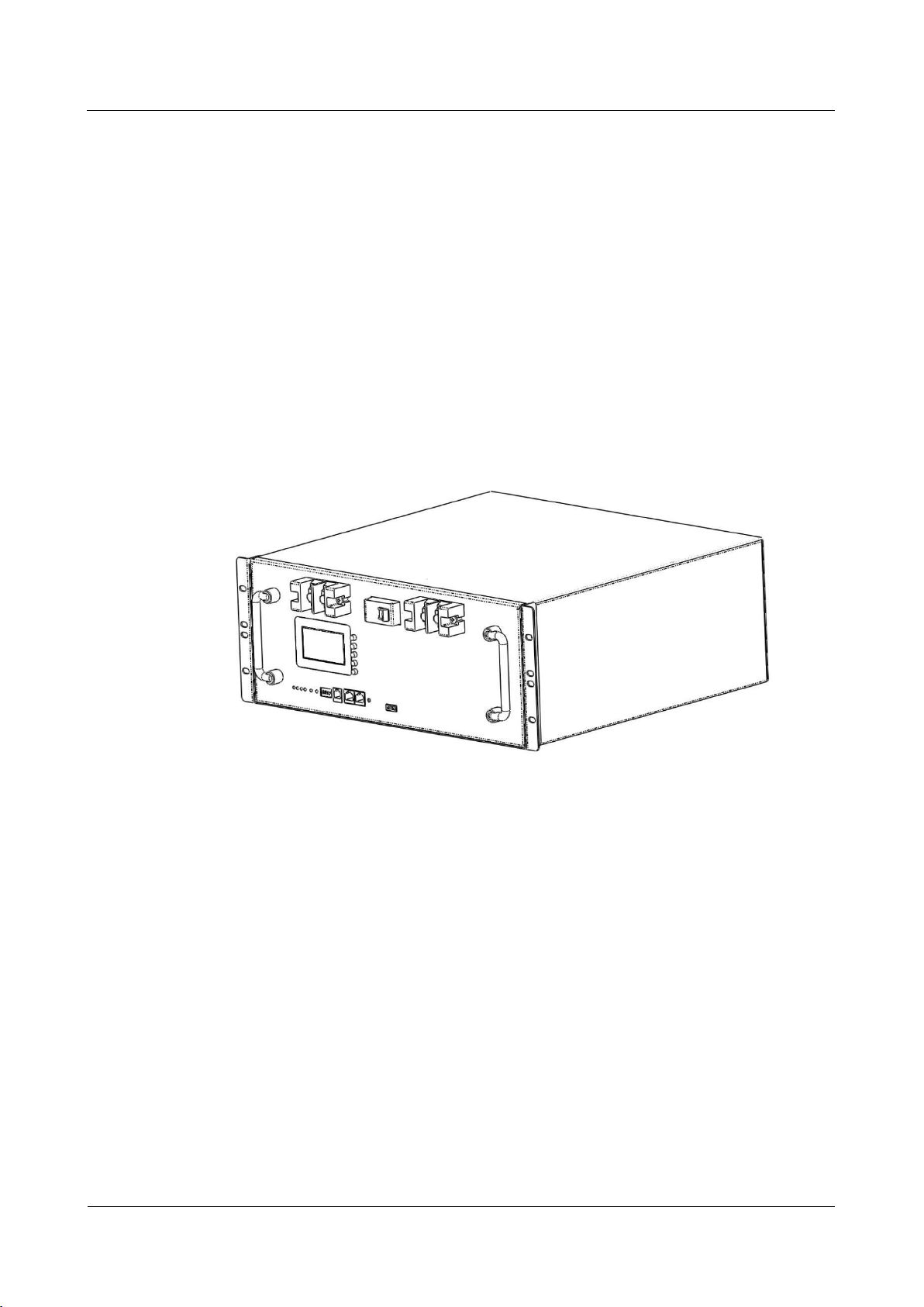
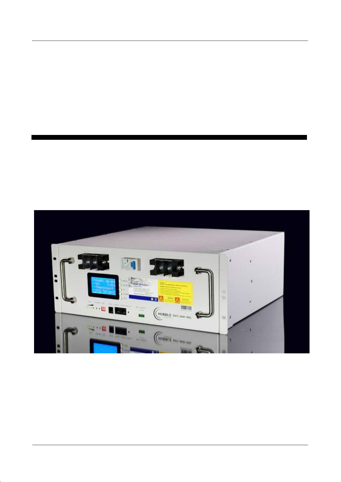
Hubble X-100 User manual

HUBBLE LITHIUM X100-48
Integrated Lithium-ion Battery
User Manual
Version:V2.0
Released Date:2020-06-08

Quick Setup
The Hubble is designed to work with 48V UPS and inverter systems and will work under AGM charge
characteristics. For solar inverters that is not on the approved integration list it is recommended to set
your inverter battery parameters manually to ensure your battery operates at optimal levels.
It is highly recommended to study the manual before installation, however for quick setup and startup of
the Hubble Lithium pack, follow the following steps:
1. Ensure cuircuit breaker is in the OFF position
2. Securely connect the DC cables to the terminals ensuring correct polarity.
3. If the unit is in sleep mode (LED lights off), press and hold RESET button for 3 seconds. The LED's
will light up.
4. Switch on DC breaker.
Inverter setup for Axpert King & VMIII (with BMS port)
The below settings is for setting up Axpert type inverters that does not have the lithium comms port.
Item Settings Value
Program 02 Maximum charge current
The Hubble is set to charge at a maximum rate of
21Amps.
Multiple batteries (2 or more) can be setup as as
20Amps x (amount of Hubble units).
Program 05 Battery Type USE
Program 12 Voltage point back to Utility 48V
Program 13 Voltage point back to Battery 51V
Program 26 Bulk Charge Voltage (C.V.) 53.2V
Program 27 Float charge voltage 51.2V
Program 29 Low DC cut-off voltage 46V
The Hubble has full integration with the Axpert King and VMII type inverters and other Axpert type
inverters with a BMS comms port.
To setup the Axpert King or VMIII, ensure you have at least firmware version 02.49 installed on the King
or VMII inverter. If you do not have this version please request it from your inverter supplier.
Connect the communications cable into port RS485-A and the other end into the Lithium RS485 port on
the inverter. Ensure you have the cable connected the correct way around as each side has a different pin
layout.
After the Lithium is connected and the inverter is powered on, change setting 5 in the inverter setup to
"Lib". This will enable the Lithium battery communication.
It takes up to 120 seconds to syncronize the communication. Once the battery icon on the inverter
flashes, communication has been successfully setup. No further settings or setup is required as the
battery will communicate to the inverter what charge, cutoff, float, bulk charge voltage should be used.

Integrated Lithium-ion Battery Pack For Solar &
UPS User Manual
FOREWORD
All Right Reserved ©
ii
FOREWORD
Overview
This manual describes the installation, history recording and parameter settings etc.
Readers
This document provides technical details regarding the tools and infrastructure used
by the following users:
Sales engineer
Technical support engineer
Installation engineer
Application engineer
Maintenance engineer
Symbol convention
The following symbols may appear in this article, and they are represented as follows:
Symbol
Indication
Used as warning in an emergency, if not avoided, it will result in
death or serious personal injury.
Used as a warning of a middle or low potential hazards, if not
avoided, it may cause minor or normal injury.

Integrated Lithium-ion Battery Pack For Solar &
UPS User Manual
FOREWORD
All Right Reserved ©
iii
Used as a warning of potential dangers, if ignore this information,
it may result in equipment broken, data lost, equipment
performance decrease and other unpredictable result.
represents the supplement information of main text to emphasize
or replenish.

Integrated Lithium-ion Battery Pack For Solar &
UPS User Manual
DIRECTORY
All Right Reserved ©
4
DIRECTORY
FOREWORD..................................................................................................................................... ii
DIRECTORY..................................................................................................................................... iv
1OVERVIEW.....................................................................................................................................6
1.1
Product specification................................................................................................................................................ 6
1.2
Product profiles..........................................................................................................................................................6
1.3
Product structure.......................................................................................................................................................7
2ILLUSTRATION............................................................................................................................. 8
2.1
Panel description....................................................................................................................................................... 8
2.2
Menu operation instructions................................................................................................................................13
2.3
The working principle.............................................................................................................................................14
2.4
The product features.............................................................................................................................................. 15
3INSTALLATION GUIDE.............................................................................................................17
3.1
Installation precaution notes................................................................................................................................17
3.2
Installation preparation..........................................................................................................................................19
3.2.1
Unpacking and inspection................................................................................................................................. 19
3.2.2
Installation tools................................................................................................................................................... 20
3.3
Installation and wiring............................................................................................................................................21
3.3.1
Standard cabinet installation.............................................................................................................................21
4MAINTENANCE..........................................................................................................................27
4.1
Electrical maintenance............................................................................................................................................27
4.2
Battery maintenance...............................................................................................................................................28
4.3
Treatment for malfunctions...................................................................................................................................28

Integrated Lithium-ion Battery Pack For Solar &
UPS User Manual
DIRECTORY
All Right Reserved ©
5
5SPECIFICATIONS........................................................................................................................33
5.1
Technical specifications..........................................................................................................................................33
5.2
The main performance index of the battery....................................................................................................34
6ENVIRONMENT PROTECTION..............................................................................................36
6.1
Environmental Label............................................................................................................................................... 36
6.2
Recycle........................................................................................................................................................................36
7APPENDIX....................................................................................................................................37
7.1
Connection cable.....................................................................................................................................................37
8 G-SENSOR……………………………………………………………………………………………………………………………..39

Integrated Lithium-ion Battery Pack For Solar &
UPS User Manual
1 OVERVIEW
All Right Reserved ©
6
1OVERVIEW
1.1 Product specification
The model of integrated lithium Ion battery (hereafter referred to as lithium
battery or PACK) for Solar & UPS is the HUBBLE X-100.
1.2 Product profiles
The lithium battery group is developed by Supplier. Belonging to one of the series of
48V communication for back-up lithium battery products, the system adopts the
international advanced lithium iron phosphate battery application technology and
BMS control technology. Due to it’s a long lifecycle, small size, light weight, stable
performance, safety and environmental protection, as well as a strong ability to adapt,
it can be used in harsh outdoor environments.

Integrated Lithium-ion Battery Pack For Solar &
UPS User Manual
1 OVERVIEW
All Right Reserved ©
7
The system integrates advanced battery manage system (BMS), including charge
and discharge management, thermal management, communication management,
balance management, data management, and realize remote centralized monitoring,
remote management and maintenance of the battery. It has outstanding advantages
in specific occasions, as a backup power supply is widely used in the remote access
network equipment, exchange, mobile communication equipment, transmission
equipment, satellite and microwave communication equipment and communication.
1.3 Product structure
The appearance of the lithium battery pack is shown in figure 1-2, for interface
description; please refer to the 2.2 panel description".
Figure1-2 Product picture

All Right Reserved ©
8
Integrated Lithium-ion Battery Pack For Solar &
UPS User Manual
2 ILLUSTRATION
2ILLUSTRATION
2.1 Panel description
The lithium battery panel as the Figure2-1 shows below.
Figure2-1 Module panel description
For detailed descriptions of each location, see the following figure2-2.

All Right Reserved ©
9
Integrated Lithium-ion Battery Pack For Solar &
UPS User Manual
2 ILLUSTRATION
Handle
Figure2-2 Panel Effect Chart
Made of galvanized steel and make it for transportation.
SOC
The meaning of SOC indication light shown in table 2-1
Table2-1 The relationship between the capacity of the battery and the light
●
●
●
●
Capacity
¤
¤
¤
¤
75%-100%
¤
¤
¤
○
50%-75%
¤
¤
○
○
25%-50%
¤
○
○
○
0%-25%
¤indicates ON,○indicates OFF。
1 Handle
2 SOC (capacity light)
3 ALM(alarm)
4 RUN
5 ADD
6 RS232
7 RS485
8 RESET / POWER ON
9 Dry Contact
10 Main panel
11 Mounting holes
12 Output-
13 MCB
14 Output﹢
15 LCD display

All Right Reserved ©
10
Integrated Lithium-ion Battery Pack For Solar &
UPS User Manual
2 ILLUSTRATION
ALM
When the battery is at fault, "ALM" light is red.
RUN
During charging, the "RUN" light will be flashing.
"RUN" and "ALM" can display the battery status, as shown in table 2-2.
Table2-2 The explanation of “RUN” and “ALM”
Function
Mark
Color
Flashing frequency
Indication
Running
RUN
Green
No light
Not working
Slow Flash(about 3 secs)
Standby state
Fast flash
Working state
Alarm
ALM
Red
No light
Normal
stable lighting
Alarm
ADD
In parallel, band switch using four dip switch to address set cell system. The
explanation of its dial switch as shown in table 2-3.
Table2-3 Band switch address code
Address Code
ADD
PACK
Definition
Explanation
1
2
3
4
5
6
OFF
OFF
OFF
OFF
/
/
0
Use Alone
ON
OFF
OFF
OFF
1
PACK
Use As
MasterPack, Can
apply RS-232
OFF
ON
OFF
OFF
2
PACK1
Use as SlavePack1
ON
ON
OFF
OFF
3
PACK2
Use as SlavePack2
OFF
OFF
ON
OFF
4
PACK3
Use as SlavePack3
ON
OFF
ON
OFF
5
PACK4
Use as SlavePack4
OFF
ON
ON
OFF
6
PACK5
Use as SlavePack5
ON
ON
ON
OFF
7
PACK6
Use as SlavePack6
OFF
OFF
OFF
ON
8
PACK7
Use as SlavePack7

All Right Reserved ©
11
Integrated Lithium-ion Battery Pack For Solar &
UPS User Manual
2 ILLUSTRATION
Address Code
ADD
PACK
Definition
Explanation
1
2
3
4
5
6
ON
OFF
OFF
ON
9
PACK8
Use as SlavePack8
OFF
ON
OFF
ON
10
PACK9
Use as SlavePack9
ON
ON
OFF
ON
11
PACK10
Use as SlavePack10
OFF
OFF
ON
ON
12
PACK11
Use as SlavePack11
ON
OFF
ON
ON
13
PACK12
Use as SlavePack12
OFF
ON
ON
ON
14
PACK13
Use as SlavePack13
ON
ON
ON
ON
15
PACK14
Use as SlavePack14
1) Address code 5 and 6 are reserved and do not play any role.
RS232
RS485
The system uses RS-232 series load data for Solar & UPS, transfering data
including: system parameters, system status and alarm information.
Telecom RS-232 generally uses 1200bps. Connected with a high-end computer,
only when the dip switch is set to Pack (Master Pack) mode, the RS-232 comms
module is effective. Connection as shown in figure 2-3.
Figure2-3 RS-232 connection schematic diagram

All Right Reserved ©
12
Integrated Lithium-ion Battery Pack For Solar &
UPS User Manual
2 ILLUSTRATION
RESET / POWER ON
When the system is in parallel mode, it can use the RS-485 serial comms for data
transfer. The main system through the Master Pack to get the data for each Slave
Pack. Connection as shown in figure 2-4.
Figure2-4 RS-485 connection schematic diagram
- Press RESET key for 3 seconds, the lithium pack will wake up from deep sleep.
- Press the RESET key for 3 seconds again, and the pack will shut down.
- When the system is running, should there be a error, press this button for 6
seconds to reset the system (press / release) to ensure the stability of the system.
Dry contact
The function of the dry node is to provide an interface for the status of the remote
monitoring battery. Failure Alarm: indicate BMS or battery fail including but not limited
to charge and discharge MOS fail, cell voltage under 0.5V, NTC disconnect.
Protection Alarm: Output short circuit, charge and discharge over current, charge and
discharge over temperature/low temperature.
Output
A total of 4 output terminals, 2 red positive, 2 black for the negative, each terminal is
the specification for M8 Stud.
MCB
MCB(Mini Circuit Breaker), protection of circuits against short-circuit currents,
protection of circuits against overload currents.
LCD display
LCD display can read Battery status, cell status, firmware version, protection/alarm,
etc.

All Right Reserved ©
13
Integrated Lithium-ion Battery Pack For Solar &
UPS User Manual
2 ILLUSTRATION
2.2 Menu operation instructions
The LCD display interface is user-friendly, as shown in figure 2-5. It provides 320 *
240 dot matrix graphic display. The LCD is able to display the alarm information in
real time, and provides the historical warning records for the user to query, and
provide a reliable basis for fault diagnosis.
Users can easily browse the battery parameters through the LCD interface, and
obtain timely access to information on the current state of the battery. The interface
displays a total of 5 menu keys, the functions described as follows.
Figure2-5 LCD Display
The commonly used button function
Display function of the button as shown in table 2-4.
Table2-4 Button function description
Main menu
Confirm, enter
Page up
Page down
Return, launch

All Right Reserved ©
14
Integrated Lithium-ion Battery Pack For Solar &
UPS User Manual
2 ILLUSTRATION
Operation procedures
1)
Press
once, the LCD display screen light up, then the welcome
interface will be shown.
2) Followed by the prompt and then click once to enter the main menu bar.
3) Scroll page up and page down ,Enter the Menu
screen, when the arrow points to the corresponding bar, press Enter
to confirm.
4) Go back on the menu bar, click .
2.3 The working principle
Lithium battery pack is equipped with charging and discharging management module
and monitoring module.
Charge and discharge management module protects battery charge and discharge
functioning, prevents overcharging, discharge over-current, the charging process by
the adapter charger to the DC input form, the discharge process is completed by
connecting the load discharge.
The monitoring module has the balance function and power, temperature and SOC.
The monitoring module transmits the real-time information collected in the
operation of the product through the comms protocol network to the monitoring
platform, and the user can observe the operation status of the battery in each group
through the display screen.
A single module has a 48V 100Ah, with a large capacity, can be used in accordance
with user requirements arbitrary combination. As shown in figure 2-6.

All Right Reserved ©
15
Integrated Lithium-ion Battery Pack For Solar &
UPS User Manual
2 ILLUSTRATION
Figure2-6 the working principle diagram
2.4 The product features
Integrated lithium battery pack for Solar & UPS has the following
characteristics:
The lithium iron phosphate as cathode material has a long life cycles, its safety
is extremely good.
The operating temperature range is: 0 ~ 45 ℃.
It has strong charge and discharge capacity, charge and discharge rate can
support 1.0C.
It can support multiple batteries for expansion.
During storage and transport, L can enter the sleep mode, in order to reduce the
loss of capacity.
The Port design is convenient; all wire harness connected to the plug,
convenient connection.
Lightweight, small size, easy to install and maintain, meets the requirements of
the standard cabinet, is able to be wall mounted, or mounted on a pole.
Battery status parameter is the system for real-time monitoring of current and
voltage, temperature, alarm and protection function.
The function of "four remote" (telemetry, remote signaling, remote regulating and
remote control), can be connected by computer with remote control center.
It is environmentally friendly.
1) Telemetry: voltage, current, temperature, SOC, SOH (optional), etc.
2) Tele-signal state of charge and discharge, overcharge / overcurrent, under voltage

All Right Reserved ©
16
Integrated Lithium-ion Battery Pack For Solar &
UPS User Manual
2 ILLUSTRATION
overcurrent alarm / alarm, environment / battery /PCBA/ battery temperature alarm, low
environmental temperature alarm, battery capacity is too low, the battery temperature /
voltage / current sensor failure alarm, battery failure alarm (just not cut off the monomer
pressure high limit alarm) (optional), battery failure alarm (optional).
3) Remote control: charge / discharge (optional), alarm sound off, intelligent intermittent
charging mode, current limiting charging mode, etc.
4) Optional: Battery charge / discharge management parameters and the output parameters
of the switching power supply system..

All Right Reserved ©
17
Integrated Lithium-ion Battery Pack For Solar &
UPS User Manual
3 INSTALLATION GUIDE
3INSTALLATION GUIDE
3.1 Installation precaution notes
Comply with local laws and regulations
When operating the equipment, make certain to comply with local laws and
regulations.
Personnel requirements
Technicians who are responsible for installation and maintenance are required to
undertake strict training first. Master the correct methods for operation and safety,
only then the installation, operation and maintenance can be carried out.
In order to maximize the efficiency of the equipment, to obtain best possible
operating results, and ensure maximum lifespan, please pay careful attention to the
correct installation and usage requirements.
Personal safety
Insulated tools and gloves should be used and worn at all times – During the
installation process, watches, bracelets, rings and other metal products should
be removed.
Avoid any fall or collision during the installation process.
Do not remove the battery components. The maintenance of the battery should
be carried out by a professional engineer.
Should be operated and supervised by engineer who have experience and can
take preventive measures for potential hazards of battery.
Field and environment
Site requirements
1) Cleanliness

All Right Reserved ©
18
Integrated Lithium-ion Battery Pack For Solar &
UPS User Manual
3 INSTALLATION GUIDE
Lithium battery packs cannot be placed in or near garbage disposals, or accidentally
dropped or placed in smaller disposal units, as their interaction with metals is likely to
cause short circuits and endanger the system and personal safety.
2) Fire protection
The room is prohibited to store flammable, explosive and other dangerous goods,
and it should be equipped with effective fire equipment (such as CO2 fire
extinguishers).
3) Ventilation and heat dissipation
In order to facilitate the operation and maintenance of equipment for the heat, the
equipment should be left around (50~30) cm around at least, left about 50cm for the
upper space. The space should be equipped with exhaust fan, to maintain good
indoor ventilation.
4) Installation requirements
Installation should be carried out as shown in figure 3-1 in order to avoid possible
risks.
Put the lithium battery on the ground (to avoid tilt, uneven ground).
Avoid placing in the sunlight, rain or wet surfaces.
Figure3-1 Requirements for installation scenarios
Environmental requirements
Ambient temperature: ( -10~+40) ℃.
Relative humidity level: 0%RH~95%RH, no condensation.
Cooling method: air cooler.
Height above sea level: match to the standard requirement of GB3859.2-93.
Verticality: no vibration and the vertical inclination does not exceed 5º.
Pollution level: Levelⅱ.
Recommended operating temperature : (20~25) ℃, humidity level control within 50%.

All Right Reserved ©
19
Integrated Lithium-ion Battery Pack For Solar &
UPS User Manual
3 INSTALLATION GUIDE
Do not install in the working environment with metal conduction type dust.
Do not put anything containing corrosive gases.
Do not put anything in the dust concentrated areas.
Do not place any items on the top of lithium-ion battery pack. People could not sit on the
battery.
Power check
Before installation, please confirm that the load capability of inlet wire meets the
requirements of the new equipment. Check to see if the power supply corresponds to
the equipment nameplate of the voltage and frequency and if the current capacity has
decreased due to the aging of the wire.
If in doubt, please check with your local power supply Consultation Department.
Ground wire
Earthing terminal is ready; zero voltage required in the room cannot exceed 5V.
DC output voltage and load capacity
Lithium-ion battery pack of rated DC output 48V.
DC output power
When installing the lithium-ion battery pack, the user should check the lithium-
ion battery pack in advance to make sure that the contacts and connectors are safely in
place to avoid an open circuit or short circuit fault.
During installation, do not connect the lithium batteries polarity in reverse or inany
way incorrectly, to avoid causing a short circuit.
Please do not connect the terminals with no security or insulation protection, so as to
avoid the risk of electric shock.
3.2 Installation preparation
3.2.1
Unpacking and inspection
Lithium batteries and accessories use packaging of cardboard boxes or wooden
boxes. When unpacking, be careful when dismantling. Inspect the device and
accessories according to the package list, to ensure it’s complete and make certain
nothing was damaged during shipping.
Before clearing the packaging, make sure that all parts are included. If equipment
or accessories are damaged in transit, or incomplete or incompatible, the equipment,
Table of contents
Other Hubble Batteries Pack manuals