Duemmegi Domino DFIGLASS User manual

Domino
DFIGLASS
DFIGLASS: Glass keypad with 6 touch
commands and backlight
DFIGLASS is a “touch” keypad available in the version with
6, and 2 commands, specifically developed for the Domi-
no bus system. The front panel is made by glass.
The available standard colors are white with white backlight
and black with blue backlight; under request, different col-
ors can be provided.
Each keypad, regardless of the number of buttons, features
an array of 6 LEDs; these LEDs are seen as generic output
points of the Domino bus, therefore the operation of the
backlight can be freely defined using the functions of the
Domino system. The keypad can be configured to generate
a beep at any touch of the buttons.
The housing of keypad DFIGLASS is suitable for the
mounting in standard wall boxes (mod. 503 or similar); it is
recommended to check the compatibility with boxes for
plasterboard walls.
The power supply needed for the module operation is car-
ried by the bus itself. On the rear side of the keypad, a
fixed terminal block allows the connection to the Domino
bus; a small pushbutton near to this terminal block allows
the address programming and a green LED shows when
the module is ready to receive the address itself; the same
LED normally flashes every 2 seconds about to signal that
the module is properly operating. A small connector (PRG)
allows the connection to the optional DFPRO tester/pro-
grammer.
DFIGLASS keypad takes 1 input and 1 output address with
the same value. A label on the rear side allows the writing
of the assigned address for an immediate visual identifica-
tion. For more details about the address assigning, refer to
the related documentation.
Note: this technical sheet refers to DFIGLASS equipped by
firmware 2.0 or hi her; this firmware is not back-compatible with
the previous versions 1.x.
Operation
DFIGLASS keypad takes 1 input address and 1 output
address having the same value. The input points report the
status of the keys (I.1 I.6), while the output points
control the LEDs (O.1 O.6) and some other functions
that as described later.
The status of the 6 LED is also reported in the input section
by points I.9 I.14 so that the status of the LEDs can be
used by other equations of the Domino bus system. The
point 15 of the input section will be activated when a failure
of the keypad occurs.
Regarding to the output section, in addition to points O.1
O.6 related to the LEDs, the points O.14 and O.15 are
available respectively to activate the backlight and the in-
ternal buzzer.
For details on the backlight and the buzzer, refer to the re-
lated paragraph.
The following figure shows the relationship between the
keys and the related bus points (the view is with terminal
block on the bottom).
I.3
O.6
I.14
I.6I.5I.4
I.2I.1
O.4
I.12
O.3
I.11
O.2
I.10
O.1
I.9
O.5
I.13
BUS _
Regarding point O.11 (Cleaning) and point O.13
(Proximity), refer to the specific paragraphs.
In summary, the available input and output points are the
following:
Point Inputs Outputs
1Key 1 Command LED 1
2Key 2 Command LED 2
3Key 3 Command LED 3
4Key Command LED
5Key 5 Command LED 5
6Key 6 Command LED 6
7- -
8- -
9Status of LED 1 Reserved
10 Status of LED 2 Reserved
11 Status of LED 3 Cleaning
12 Status of LED -
13 Status of LED 5 Proximity
14 Status of LED 6 Backlight
15 Keypad failure Buzzer
16 Reserved -
DUEMMEGI s.r.l. - Via Longhena, - 20139 MILANO
Tel. 02/57300377 - Fax 02/55213686 – www.duemmegi.it
Rel.: 2.2 May 2016 Page 1 of 5

Domino
DFIGLASS
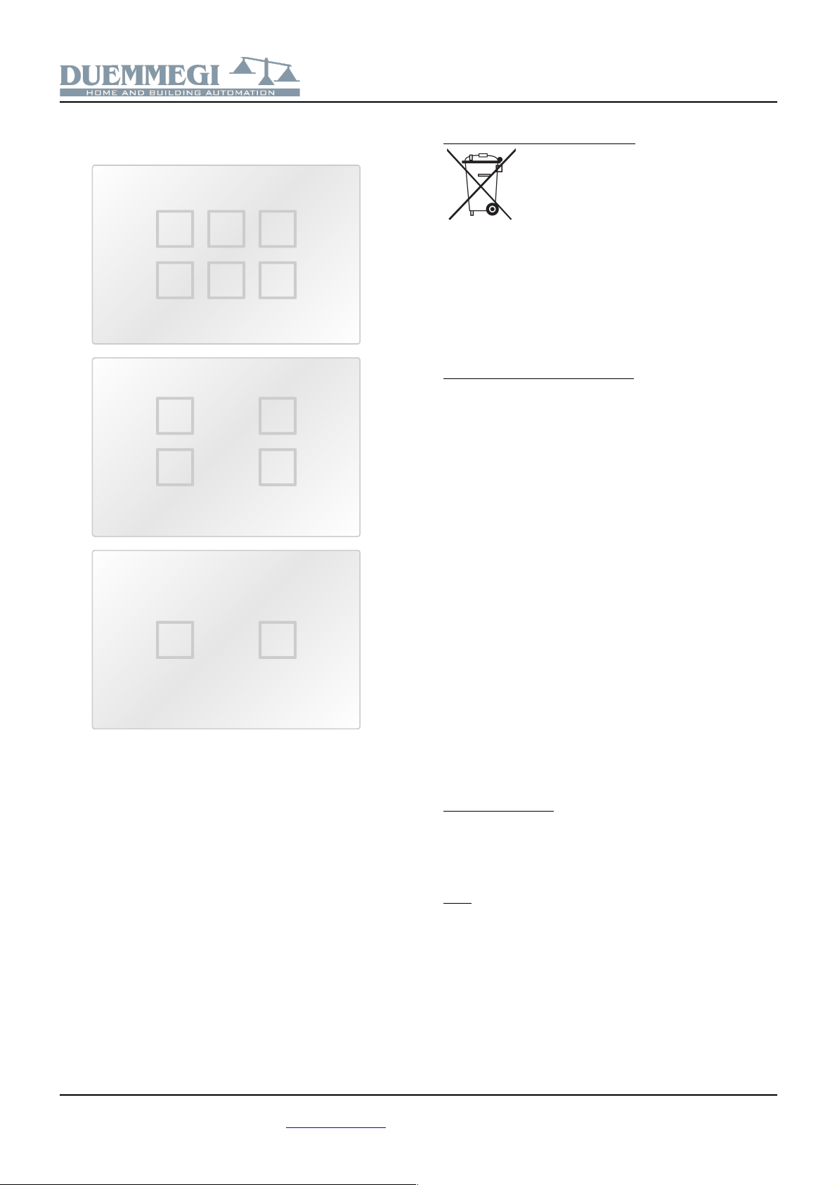
The following figures show the assignment of the input and
output points for the different available versions in 6, and
2 keys; in all versions, the number of LEDs is always 6.
I.3
O.6
I.14
I.6I.5I.4
I.2I.1
O.4
I.12
O.3
I.11
O.2
I.10
O.1
I.9
O.5
I.13
I.3
O.6
I.14
I.6I.4
I.1
O.4
I.12
O.3
I.11
O.2
I.10
O.1
I.9
O.5
I.13
O.6
I.14
I.3I.1
O.4
I.12
O.3
I.11
O.2
I.10
O.1
I.9
O.5
I.13
As said before, the operation of the 6 LED outputs can be
freely defined by equations using the functions of Domino
system.
In addition, it is also possible to program by equations the
output points related to the proximity and to the backlight,
while the equations are not allowed for the output points re-
lated to cleaning and buzzer.
Backlight and Buzzer
The square outline of each key of DFIGLASS can be illumi-
nated by a LED (or two LEDs in the case of 2 keys
version). There are 2 levels of backlight, a very low level
and common to all 6 LEDs and one of much higher level in-
dependent for each one of the 6 LEDs.
The “common” backlight keeps illuminated all the keys so
that, for example, they can be easily identified in the dark-
ness; this type of backlight is controlled by the DFIGLASS
configuration panel available in BDTools or DCP Ide. To
access to this panel, select Programming from the main
menu, then Module's Configuration and finally DFIGLASS;
the following window will be shown:
Module's Address is the address of DFIGLASS to be con-
figured; for the backlight, like for the buzzer, 3 options are
available:
Always Disabled: this means that the backlight (or the
buzzer) is always turned off and it cannot be activated not
even by acting on the output point 1 (15 in the case of the
buzzer) that will be always OFF
Always Enabled: this means that the backlight (or the
buzzer) is always turned on and it cannot be deactivated
not even by acting on the output point 1 (15 in the case of
the buzzer) that will be always ON
Controlled by Bus: this means that the backlight (or the
buzzer) can be controlled (turned on and off) by acting on
the output point 1 (15 in the case of the buzzer)
Note: the output point 14 (Backli ht) can be controlled by equa-
tions (pointed that the option “Controlled by Bus” in the confi ura-
tion panel has been activated). The output point 15 (Buzzer), on
the contrary, CANNOT be controlled by equations.
Once selected the desired options, press the Program but-
ton; the Read button allows to see the current settings of
the specified DFIGLASS, while the button ID & Ver. allows
to read the firmware version (which can be updated via
bus).
The activation of an output point from 1 to 6 will switch on
to a high level the corresponding LED, regardless of how
the common backlight has been set; it is thus possible to
have an indicator light by means of appropriate program-
ming of the LEDs.
DUEMMEGI s.r.l. - Via Longhena, - 20139 MILANO
Tel. 02/57300377 - Fax 02/55213686 – www.duemmegi.it
Rel.: 2.2 May 2016 Page 2 of 5

Domino
DFIGLASS
Cleaning mode
The “cleaning” mode allows to clean the glass avoiding the
risk to cause a unwanted detection of the keys, and thus a
consequent possible actuation of some outputs.
To enter the cleaning mode, press at the same time the
keys 1-2-3 or -5-6 for 2.5 seconds, or activate point 11 of
the output section. For keypad versions without middle key
(2 and keys), the same rule applies, in the sense that the
“blank” area between the two outside buttons has to be
touched.
When the cleaning function is activated, the backlight blinks
(0.5s ON and 0.5s OFF). The output point 11 reports the
status of the cleaning function (activated when the function
is ON).
To exit the “cleaning” mode, the same operation must be
performed (pressing three points for 2.5 seconds at the
same time or disabling the point 11 of the output section).
The cleaning mode will be however automatically deactivat-
ed after 2 minutes.
Note: output point 11 (Cleanin ) CANNOT be controlled by equa-
tions.
Proximity mode
In some applications, for instance in bedrooms, the back-
light always ON is not appreciated, even if at very low level;
on the other hand, acting on the keys in the darkness may
be a problem.
To answer to this need, the proximity mode can be activat-
ed: a first touch” on any key will cause the lighting of the
keypad backlight, without any unwanted activation, thus al-
lowing to see the keys in the darkness.
The point 13 of the output section controls the proximity
mode: in this case the first detection of any keys will be in-
terpreted as proximity detection and the effect will be the
lighting of the keypad.
The backlight of the keypad will remain ON for 2 seconds
after the key release; during this time, any other “touch ” of
the keys will be accepted and processed.
The just described proximity mode will be however by-
passed when:
•it is disabled in the configuration panel
•the backlight is already ON
•at least a LED is ON
In this case, the “touched” key will be immediately detected
and processed.
Note: output point 13 (Proximity) can be controlled by equations.
Module connection
DFIGLASS keypad requires only the connection to the Do-
mino bus as shown in the following schematic diagram.
_
DUEMMEGI
MILANO-ITALY
DFIGLASS-6T
Domino
BUS _
ADDRESS
BUS
UP
Programming examples
As said before, the status of output points related to the 6
LEDs is replicated in the input section (points 9 1 ).
This architecture allows to easily create commands for
lighting as shown in the following example.
Suppose to have assigned the address 1 to DFIGLASS
keypad and that you want to control a lamp (connected for
instance to the output O 2.1) by the key 1 of DFIGLASS.
Also assume that the LED related to the key 1 has to follow
the status of the lamp.
A possible program can be the following:
DFIGLASS = ( 1 ) // address 1 is DFIGLASS
O1.1 = TI1.1 // to le LED1
O42.1 = I1.9 // lamp output
The key I1.1 of DFIGLASS changes, at each touch, the
status of the corresponding LED; the status of the LED1,
reported by I1.9, is then copied to the output O42.1 con-
nected to the lamp.
In this way there is the assurance that the lamp and the
LED are always aligned because the status of the LED will
be always reported to the lamp.
Note the statement DFIGLASS = ( 1 ) specifying that
address 1 is a DFIGLASS keypad; this statement (one for
each DFIGLASS keypad) is mandatory and, if omitted,
some errors may occur during the program compiling or
when attempting to transfer the program to the device.
If the application requires to switch ON the LED when the
light is OFF (for example, to locate the key in the
darkness), simply modify the previous program as follows:
DUEMMEGI s.r.l. - Via Longhena, - 20139 MILANO
Tel. 02/57300377 - Fax 02/55213686 – www.duemmegi.it
Rel.: 2.2 May 2016 Page 3 of 5
Domino
DFIGLASS
DFIGLASS = ( 1 ) // address 1 is DFIGLASS
O1.1 = TI1.1 // to le LED1
O42.1 = !I1.9 // lamp output
The status of an LED, of course, can be reported on anoth-
er LED; this is useful in the case of keypads with 2 keys to
turn on both the LEDs below and above that key (however
according to the preferences of the user).
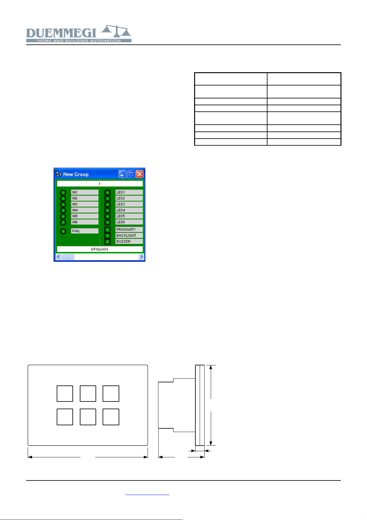
Mapping
DFIGLASS keypad is shown in the map of BDTools or DCP
Ide as a mixed input/output module, like shown in the fol-
lowing figure.
As for all other Domino modules, the background is in
green color if the module is connected and properly work-
ing, otherwise the background is in red color. The status of
input and output points is shown on the map in red or green
color depending on the status ON or OFF respectively.
Output points BACKLIGHT and BUZZER allow the activa-
tion or deactivation of the common backlight and buzzer;
these points can be controlled or less depending on how
the keyboard has been set (see the paragraph Backlight
and Buzzer).
Outline dimensions
Technical characteristics
Power supply (bus side) By specific centralized power
supply mod. DFPW2
Current consumption bus side Equivalent to 3 standard
modules
Number of keys 6, and 2 with LED backlight
Buzzer Internal, it can be disabled
Colors Black with blue LEDs
White with white LEDs
Operating temperature -5 +50 C
Storage temperature -20 +70 C
Protection degree IP20
DUEMMEGI s.r.l. - Via Longhena, - 20139 MILANO
Tel. 02/57300377 - Fax 02/55213686 – www.duemmegi.it
Rel.: 2.2 May 2016 Page of 5
80mm
120mm
9mm
6mm
Domino
DFIGLASS
Available versions Correct disposal of this product
(Waste Electrical & Electronic Equipment)
(Applicable in the European Union and other
European countries with separate collection sys-
tems). This marking on the product, accessories or
literature indicates that the product should not be
disposed of with other household waste at the end
of their working life. To prevent possible harm to
the environment or human health from uncontrolled waste dispos-
al, please separate these items from other types of waste and re-
cycle them responsibly to promote the sustainable reuse of materi-
al resources. Household users should contact either the retailer
where they purchased this product, or their local government of-
fice, for details of where and how they can take these items for en-
vironmentally safe recycling. This product and its electronic ac-
cessories should not be mixed with other commercial wastes for
disposal.
Installation and use restrictions
Standards and regulations
The design and the setting up of electrical systems must be per-
formed according to the relevant standards, guidelines, specifica-
tions and regulations of the relevant country. The installation, con-
figuration and programming of the devices must be carried out by
trained personnel.
The installation and the wiring of the bus line and the related de-
vices must be performed according to the recommendations of the
manufacturers (reported on the specific data sheet of the product)
and according to the applicable standards.
All the relevant safety regulations, e.g. accident prevention regula-
tions, law on technical work equipment, must also be observed.
Safety instructions
Protect the unit against moisture, dirt and any kind of damage dur-
ing transport, storage and operation. Do not operate the unit out-
side the specified technical data.
Never open the housing. If not otherwise specified, install in closed
housing (e.g. distribution cabinet). Earth the unit at the terminals
provided, if existing, for this purpose. Do not obstruct cooling of the
units. Keep out of the reach of children.
Setting up
The physical address assignment and the setting of parameters (if
any) must be performed by the specific softwares provided togeth-
er the device or by the specific programmer. For the first installa-
tion of the device proceed according to the following guidelines:
•Check that any voltage supplying the plant has been removed
•Assign the address to module (if any)
•Install and wire the device according to the schematic dia-
grams on the specific data sheet of the product
•Only then switch on the 230Vac supplying the bus power sup-
ply and the other related circuits
Applied standards
This device complies with the essential requirements of the follow-
ing directives:
201 /30/UE (EMC)
201 /35/UE (Low Voltage)
2011/65/UE (RoHS)
Note
Technical characteristics and this data sheet are subject to change
without notice.
DUEMMEGI s.r.l. - Via Longhena, - 20139 MILANO
Tel. 02/57300377 - Fax 02/55213686 – www.duemmegi.it
Rel.: 2.2 May 2016 Page 5 of 5
Table of contents


