Duevi EzyDriveCAM Assembly instructions

This device meets the R&TTE requirements (European Union)
EzyDrive
EzyDriveEzyDrive
EzyDriveCAM
D I G I T A L V I D E O R E C O R D E R
HARDWARE INSTALLATION MANUAL
(VERSION 3.0)
Software manua on y on CD
This manual may be subject to change without notice

2
Thank you for choosing our product.
We invite you to read carefully these directions before installing and using this device in order to fully make
the most of all its capacities.
1. INTRODUCTION
THE MANU ACTURER SHALL NOT BE LIABLE OR ANY IMPROPER USE O THE PRODUCT,
INCORRECT INSTALLATION OR AILURE TO COMPLY WITH INSTRUCTIONS O THIS MANUAL
AND THE LAW REGARDING ELECTRICAL SYSTEMS.
DO NOT CLEAN THE CASE WITH ALCOHOL OR OTHER LIQUID CLEANER BUT ONLY WITH A
CLOTH BARELY DAMPENED WITH WATER.
IN CASE O AILURE O THE DEVICE DO NOT TRY TO REPAIR IT YOURSEL BUT BRING TO THE
NEAREST AUTHORIZED SERVICE CENTER.
E
EE
EzyMegaCAM
zyMegaCAMzyMegaCAM
zyMegaCAM is a megapixel camera with recording storage on board that can be questioned by a vision
and programming software (EzyViewCAM) through locale network, power line (HomePlug® system) or
remote connection (WEB).
It can be visualized and programmed by EzyTV also, for management without PC.
The non-volatile memory inserted in the device (up to two D card) make possible to store the video
directly in MPG4 format, therefore it is not needed any server or additional video recorder.
The rechargeable backup battery allows to record even in case of power supply 12 V lack.
The EzyMegaCAM are equipped of:
•alarm input: NC at +12 V
•open-collector output useful for command a device from remote
•onboard IR detector, for detect the presence of strangers and activate the video recording
•light sensor: EzyCAM defines day and night, adapting the C-MOS sensor parameters for having
always the best image quality during day and night.
3
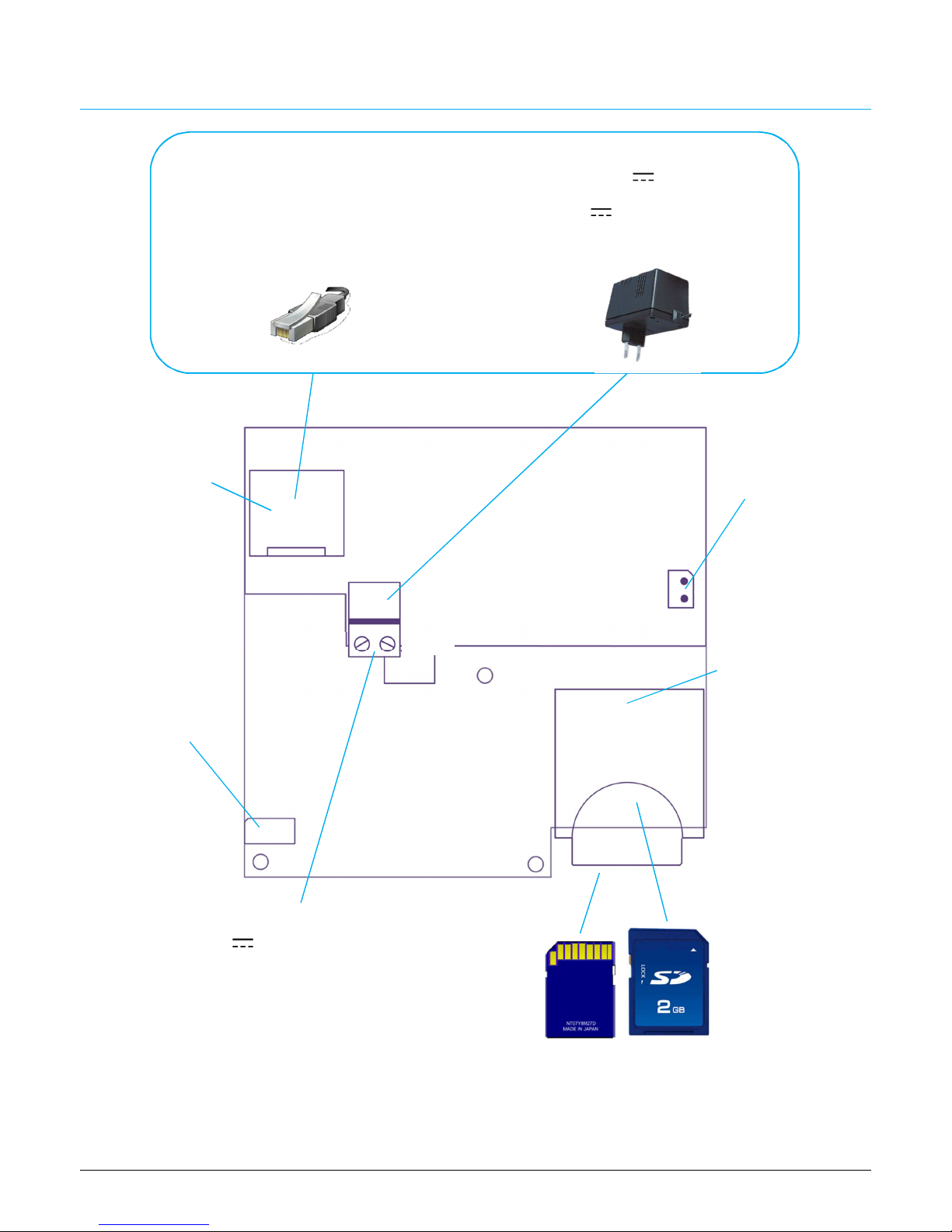
2. DEVICECONNECTION
Figure 1 – E ectronic board of EzyMegaCAM
LAN
(connector side)
POWER SUPPLY
Can be in two different types. When using PoE, do NOT connect 12 V power supply!
12 V POWER SUPPLY
PoE
Power is supplied by LAN (if present a Power
over Ethernet system)
+12V
GND
BAT
Backup battery
connector
LAN
LAN connector RJ45
type
Power supp y 12 V
Power 12 V
Not necessary if using the PoE (LAN)
system
MASTER s ot
Lower slot
Use ONLY this one
in case of single SD
card
SLAVE s ot
Upper slot
DO NOT use in case
of single SD card
Doub e SD s ot
To install up to
two SD cards
(must be
identical).
Insert/remove
only with device
completely
unpowered
Input/Output
Use provided cable

4
Figure 2 – E ectronic board of EzyMegaCAM
POF
(connector side)
POWER SUPPLY
The camera can be powered:
power supply 12 ÷ 30 V or power supply 24 V
The POWER connector does not have preferential polarity (even in case of CC)
POWER
BAT
Backup battery
connector
POF1 LED
Network activity
MASTER s ot
Lower slot
Use ONLY this one
in case of single SD
card
SLAVE s ot
Upper slot
DO NOT use in case
of single SD card
Doub e SD s ot
To install up to
two SD cards
(must be
identical).
Insert/remove
only with device
completely
unpowered
Input/Output
Use provided cable
POF1
Plastic optic fiber
connector (LAN)
POF2
Plastic optic fiber
connector (LAN)
POF2 LED
Network activity
5
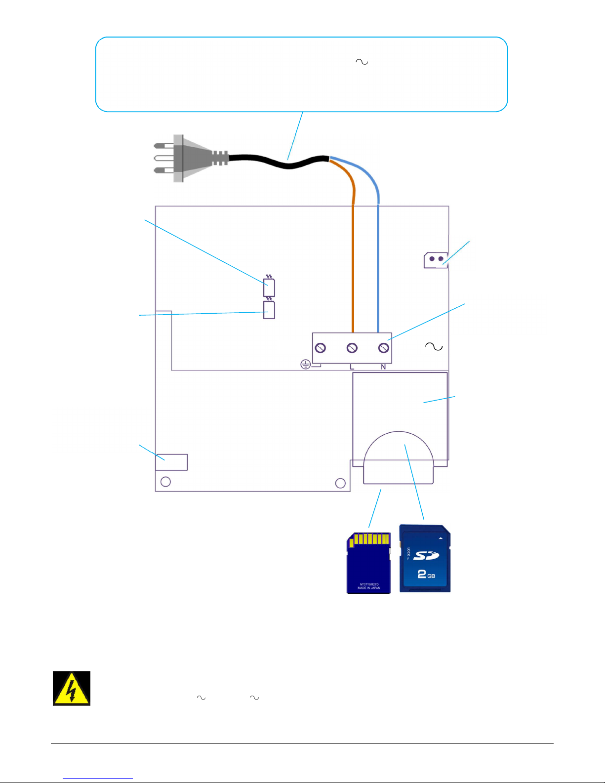
Figura 3 – E ectronic board of EzyMegaCAM
PL
(connector side)
TO PREVENT
TO PREVENT TO PREVENT
TO PREVENT THE RISK O ELECTRIC SHOCK, OPEN THE DEVICE COVER ONLY
THE RISK O ELECTRIC SHOCK, OPEN THE DEVICE COVER ONLY THE RISK O ELECTRIC SHOCK, OPEN THE DEVICE COVER ONLY
THE RISK O ELECTRIC SHOCK, OPEN THE DEVICE COVER ONLY
WHEN THE 110
WHEN THE 110WHEN THE 110
WHEN THE 110
V
VV
V
/ 230
/ 230/ 230
/ 230
V
VV
V
POWER SUPPLY IS SWITCHED O
POWER SUPPLY IS SWITCHED OPOWER SUPPLY IS SWITCHED O
POWER SUPPLY IS SWITCHED O .
..
.
POWER
and DATA
The camera is powered directly by 230 V power line
Data communication from/to the camera is made through power line by HomePlug® 1.0 system
GND
230 V
BAT
Backup battery
connector
Activity LED
Data transfer
MASTER s ot
Lower slot
Use ONLY this one
in case of single SD
card
SLAVE s ot
Upper slot
DO NOT use in case
of single SD card
Doub e SD s ot
To install up to
two SD cards
(must be
identical).
Insert/remove
only with device
completely
unpowered
Input/Output
Use provided cable
Link LED
Connection to
HomPlug system
230 V
AC
N = Neutral (blue)
= Phase (brown)

6
Input/Output
Figure 4 – Input/output connector and specia cab e scheme
Connection of the input
Figure 5 – Connection scheme of the digita input to an externa detector
7
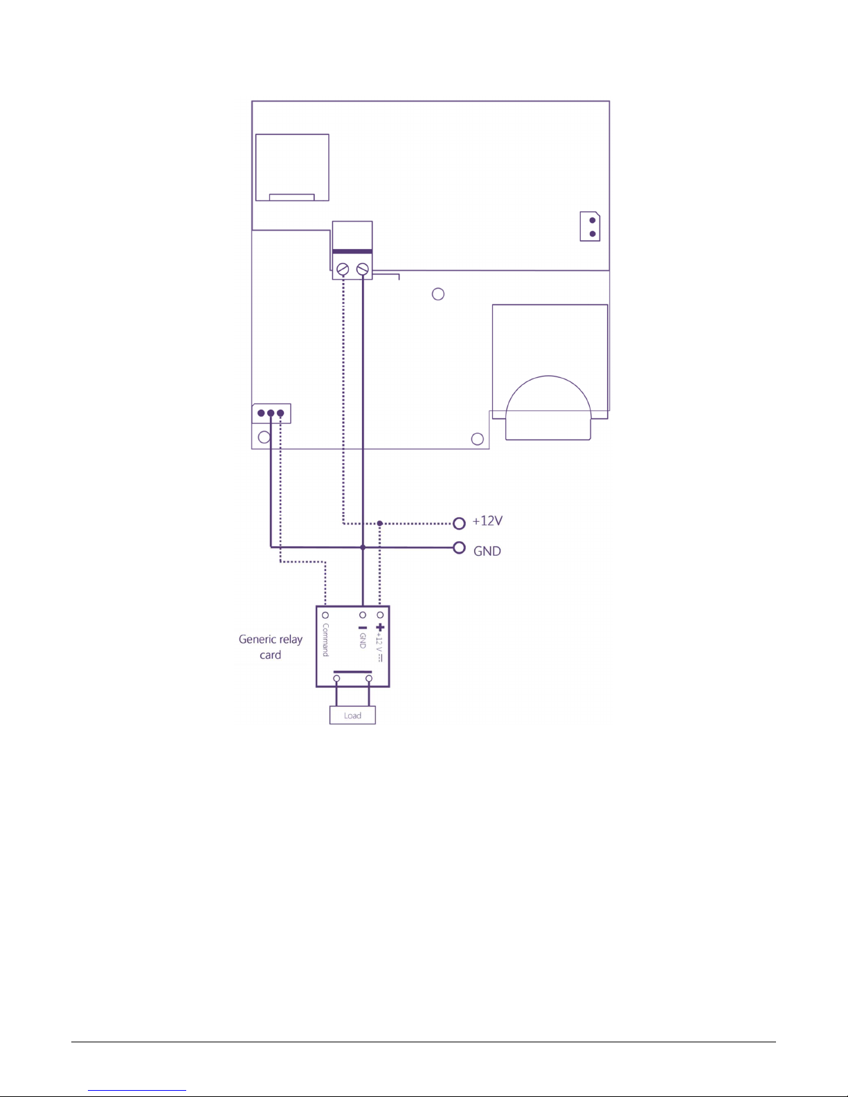
Connection of the output
Figure 6 – Connection scheme of the digita output to a re ay board to drive a oad

8
3. Installation
Before the installation
Each EzyCAM device must be configured before its use.
At the first start and configuration DO NOT CONNECT neither SD memory cards nor BATTERY, only
main power supply and data connection.
After first configuration is possible to add D cards and battery.
It is recommended to connect the EzyCAM to be programmed directly to PC and not through a LAN.
Program the camera, then install and finally make some test and adjustments.
To program is required:
a) PC with fixed IP address (see network settings) and EzyViewCAM software installed (for the use of
EzyTV see proper manual)
b) disable or configure firewall and/or protection software (they can block communication between PC
and EzyCAM)
At the end of programming it will be possible to connect all the EzyCAM to the network.
After each programming, replace with the next EzyCAM:
LAN connection: proceed one
EzyCAM at time
EzyCAM 1
EzyCAM 2
EzyCAM 3
EzyCAM n

Installation and settin s
1. 1. Mount the lens (standard plug Board-Mount / M12) screwing on the ferrule that surround the CMOS
sensor. On some models the lens could be already mounted.
WE RECOMMEND to follow carefully the mounting instruction on the lens manual or product manual to
avoid to damage of the optical lens.
2. Connect the main power supply (do not connect backup battery)
3. LAN and POF version: connect data cable (ethernet or PO + adapter) to the EzyCAM and to PC (or
to LAN and connect PC to the same network).
PL version: connect – if is used the software for PC – the HomePlug adapter to the power line where is
the EzyMegaCAM and to the LAN of the PC.
Use with EzyTV: it is not necessary to make further connection.
4. Launch EzyViewCAM software.
Set for each EzyCAM:
•Site, position and name
•IP address, subnet and port
•Device password
Once all parameters are set is possible to visualize EzyCAM by dragging its name in visualization area.
5. Adjust image (focus, video CMOS parameters) by acting on lens and through software settings (CMOS).
6. Power off the EzyCAM and insert one or two Secure Digital (SD) memory cards in apposite slots (one
slot on upper side and one on lower side) pushing until a “click” (lock of card).
To extract the memory cards just push each card to unlock then pull it gently outwards.
EzyMegaCAM works correctly only if the two D cards are identical (same memory size)
Not all D memory cards are compatible.
It’s necessary to use HC type D cards, at least “class 6” category (check before buying, on the package or
label).
7. Install the EzyCAM in its place
WE RECOMMEND to ALWAY test communication before definitively fix the devices

10
Cables
or the cab e passage are available two ways:
1)
1)1)
1) Cab e g and: push with strength the cables through the membrane that will be adapted automatically
around the cables.
2)
2)2)
2) Cab e path: break it following the form and pass the cable.
Connector on surface version
Connect power and network cables on the back of the device (without need to open the case):
LAN – RJ45
Power
12
V
–
+
Cab e
g and
Cable path
Table of contents


