Dukane AiM Installation and operating instructions

AN525 (REV 02) © Dukane 2018. All Rights Reserved.
Page 1 of 21
DUKANE
APPLICATION NOTE
AN525
Intelligent Assembly Solutions
iQ Series
ULTRASONIC PROBE SYSTEM
AiM
Automation Interface Guidelines

AN525 (REV 02) © Dukane 2018. All Rights Reserved.
Page 2 of 21
DUKANE
APPLICATION NOTE
AN525
Intelligent Assembly Solutions
Contents
Programming the Aim Generator for use with hard wired connections using iQ Commander....................3
The following control parameters are available via iQ Commander™: 3
Parameters that can be obtained via iQ Commander™3
Operations that can be done via iQ Commander™3
Generator Cloning: ..................................................................................................................................3
Saving Setups: .........................................................................................................................................3
System I/O Cable Pinouts.........................................................................................................................4
System Input/Output Cables 4
System Inputs Description 5
Connecting an Input to a PLC Sourcing Output Card 5
Connecting an Input to a PLC Sinking Output Card 6
Connecting an Input to a Relay Contact Closure 7
System Output Description 8
Connecting an Output to a PLC Sourcing Input Card 8
Connecting an Output to a PLC Sinking Input Card 9
Connecting an Output to a Relay Contact Closure 10
Connecting a Distance Encoder .............................................................................................................. 11
Remote Setups ...................................................................................................................................... 12
Remote Setup Switching 12
Connecting an Automation Safety Circuit............................................................................................... 13
iQ AiM Automation Controlled Probe Generator Timing Diagrams ......................................................... 14
AiM Weld-by-Automation Timing Diagram 14
AiM (Weld-by-Time) Timing Diagram 15
AiM (Weld-by-Energy) Timing Diagram 16
AiM With MPCQ (Weld-by-Automation) Timing Diagram 17
........................................... 18
Additional information can be found at the following links: ................................................................... 20

AN525 (REV 02) © Dukane 2018. All Rights Reserved.
Page 3 of 21
DUKANE
APPLICATION NOTE
AN525
Intelligent Assembly Solutions
Programming the Aim Generator for use with hard wired connections using iQ Commander
IQ Commander is a PC based utility that can be used to communicate to Dukane generators that contain a USB port. This utility can
be downloaded from the following location:
https://update.dukane.com/
The following control parameters are available via iQ Commander:
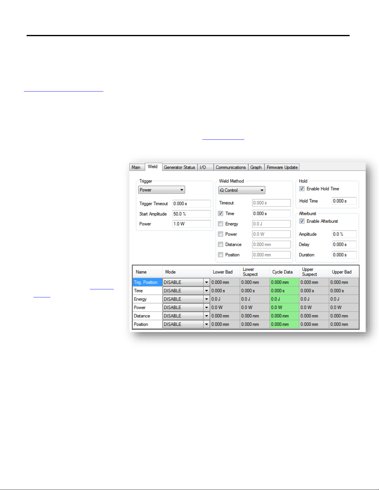
1. Set weld method and associated values.
2. Set Amplitude, Ramp Up Time, and Ramp Down Time.
3. Enable iQ Control and program Weld Methods.
4. Enable and set Trigger by Power or Trig. Distance parameters. (See App Note AN506 for Trigger by Power settings)
5. Enable and set Hold and Afterburst.
6. Enable checking for Good, Suspect and Bad Parts.
7. Configure advanced I/O settings.
Parameters that can be obtained
via iQ Commander
1. All parameters that are configured
via iQ Commander.
2. Real time data which includes
welder state, frequency, power,
position, and amplitude.
3. Weld cycle data from previous weld.
Operations that can be done via
iQ Commander
1. Scan an ultrasonic stack to
determine the optimal Free Run
Frequency value. (See App Note
AN512)
2. Test the ultrasonic Stack for
operating frequency and power.
3. Weld a part.
4. Select a probe when an MPC
module is connected.
NOTE: If Weld Time is not used as a control parameter, a weld Timeout needs to be programmed.
Generator Cloning:
If a generator needs to be swapped and a new generator put in its place, it is possible to clone the generator setups and complete
configuration so that it can be loaded into the new generator. This is done through iQ Commander by going to the File menu and
selecting Clone Generator to File. This will save the complete generator configuration and setups for later use. Cloning can only be
performed on generators where the model number precisely matches both generators. If the model number does not match exactly,
cloning will be prohibited.
Saving Setups:
Setups can be saved by opening the FILE menu and clicking on Save A

AN525 (REV 02) © Dukane 2018. All Rights Reserved.
Page 4 of 21
DUKANE
APPLICATION NOTE
AN525
Intelligent Assembly Solutions
System I/O Cable Pinouts
Pin
Color
Description
J5-1
BLK/RED
+22V CURRENT LIMITED POWER SUPPLY (500mA MAX)
J5-2
RED/BLK
+22V RETURN (iQ CHASSIS GROUND)
J5-3
BLK/WHT
E-STOP OUTPUT
J5-4
WHT/BLK
E-STOP INPUT
J5-5
BLK/GRN
REMOTE SETUP SELECTION BIT 0 INPUT
J5-6
GRN/BLK
REMOTE SETUP SELECTION BIT 1 INPUT
J5-7
BLK/BLU
REMOTE SETUP SELECTION BIT 2 INPUT
J5-8
BLU/BLK
REMOTE SETUP SELECTION BIT 3 INPUT
J5-9
BLK/YEL
AUTOMATION CYCLE STOP INPUT
J5-10
YEL/BLK
FRONT PANEL LOCKOUT INPUT
J5-11
BLK/BRN
ISOLATED INPUT COMMON
J5-12
BRN/BLK
ULTRASOUND ACTIVATION/CYCLE START INPUT
J5-13
BLK/ORN
ISOLATED ULTRASOUND COMMON
J5-14
ORN/BLK
ANALOG DISTANCE INPUT (0-10VDC)
J5-15
RED/WHT
ANALOG AMPLITUDE INPUT (0-10VDC)
J5-16
WHT/RED
ANALOG GROUND
J5-17
RED/GRN
ANALOG POWER OUTPUT (1mV = 1 WATT) (0-10VDC)
J5-18
GRN/RED
ANALOG AMPLITUDE OUTPUT (0-10VDC)
J5-19
RED/BLU
ULTRASOUND STATUS OUTPUT
J5-20
BLU/RED
ANY FAULT STATUS OUTPUT
J5-21
RED/YEL
OVERLOAD STATUS OUTPUT
J5-22
YEL/RED
BAD PART STATUS OUTPUT
J5-23
RED/BRN
GOOD PART STATUS OUTPUT
J5-24
BRN/RED
READY STATUS OUTPUT
J5-25
RED/ORN
MPC READY STATUS OUTPUT
J5-26
ORN/RED
ISOLATED OUTPUT COMMON
Note: The descriptions shown are for the default I/O settings. Almost all Inputs are programmable to other input
functions and all outputs to other output functions. The exception is the ULTRASOUND ACTIVATION / CYCLE START
INPUT which cannot be programmed to another function. For other functions and detailed signal descriptions, please
refer to the product manual.
System Input/Output Cables
Part Number
Length
200-2119-03M
3 meters
200-2119-05M
5 meters
200-2119-07M
7 meters
200-2119-09M
9 meters
200-2119-11M
11 meters
200-2119-13M
13 meters

AN525 (REV 02) © Dukane 2018. All Rights Reserved.
Page 5 of 21
DUKANE
APPLICATION NOTE
AN525
Intelligent Assembly Solutions
System Inputs Description
All System Inputs are optically isolated from the internal circuits and can be connected to sinking or sourcing PLC output
cards. The inputs will draw approximately 10mA with a 24Vdc supply. The Systems Inputs can also be configured for a
contact closure if necessary.
Connecting an Input to a PLC Sourcing Output Card
Notes:
1. All System Inputs share the same isolated common (J5-11) except Ultrasound Activation/Cycle Start Input (J5-12)
which has a separate isolated common (J5-13). It is critical that the isolated commons are connected to +24 Vdc
Supply or 0 Vdc Return.
2. J5-1 can be used in place of the 24 Vdc supply. If so, J5-11 must be connected to J5-2. Use J5-13 in place of
J5-11 for the Ultrasound Activation/Cycle Start Input.
Warning: Any connection to the Ultrasound Activation/Cycle Start Input (J5-12) should be disabled during an emergency
stop condition.
+24 Vdc Supply
PLC Output Card
Contact closure or
transistor output
iQ System Inputs
0 Vdc Return
Isolated Input Common
J5-11
PLC Digital Outputs
Sourcing Current
iQ Digital Input
Sinking Current

AN525 (REV 02) © Dukane 2018. All Rights Reserved.
Page 6 of 21
DUKANE
APPLICATION NOTE
AN525
Intelligent Assembly Solutions
Connecting an Input to a PLC Sinking Output Card
Notes:
1. All System Inputs share the same isolated common (J5-11) except Ultrasound Activation/Cycle Start Input (J5-12)
which has a separate isolated common (J5-13). It is critical that the isolated commons are connected to +24 Vdc
supply or 0 Vdc Return.
2. J5-1 can be used in place of the 24 Vdc supply. If so, J5-11 must be connected to J5-1 and 0 Vdc Return to J5-2.
Use J5-13 in place of J5-11 for the Ultrasound Activation/Cycle Start Input.
Warning: Any connection to the Ultrasound Activation/Cycle Start Input (J5-12) should be disabled during an emergency
stop condition.
+24 Vdc Supply
PLC Output Card
Contact closure or
transistor output
iQ System Inputs
0 Vdc Return
Isolated Input Common
J5-11
PLC Digital Outputs
Sinking Current
iQ Digital Input
Sourcing Current

AN525 (REV 02) © Dukane 2018. All Rights Reserved.
Page 7 of 21
DUKANE
APPLICATION NOTE
AN525
Intelligent Assembly Solutions
Connecting an Input to a Relay Contact Closure
Notes:
1. All System Inputs share the same isolated common (J5-11) except Ultrasound Activation/Cycle Start Input (J5-12)
which has a separate isolated common (J5-13). It is critical that the isolated commons are connected to +24 Vdc
supply or 0 Vdc Return.
2. ituted for the +24 Vdc supply above. Connect J5-1 to Isolated
Common (J5-11) and 0 Vdc Return to J5-2. Use J5-13 in place of J5-11 for the Ultrasound Activation/Cycle Start
Input. Connecting the System Inputs in this way would be similar to activating DPC series System Inputs.
Warning: Any connection to the Ultrasound Activation/Cycle Start Input (J5-12) should be disabled during an emergency
stop condition.
iQ Digital Input
Sourcing Current
+24Vdc Supply
PLC Output Card or External Relay
iQ System Inputs
0Vdc Return
Isolated Input Common
J5-11
PLC Digital Outputs
Sinking Current

AN525 (REV 02) © Dukane 2018. All Rights Reserved.
Page 8 of 21
DUKANE
APPLICATION NOTE
AN525
Intelligent Assembly Solutions
System Output Description
All System Outputs are optically isolated from the internal circuits and can be connected to sinking or sourcing PLC input
cards. When J5-1 is used to power the outputs, the total maximum output current for all outputs combined is 500mA. If
an external supply is used, as shown in the drawing below, each output can sink or source up to 500mA.
Connecting an Output to a PLC Sourcing Input Card
Notes:
1. All System Outputs share the same isolated common (J5-26). It is critical that the isolated output common is
connected to +24 Vdc supply or 0 Vdc Return.
2. J5-1 can be used in place of the 24 Vdc supply. If so, J5-26 must be connected to J5-2.
iQ Digital Outputs
Sinking Current
+24 Vdc Supply
iQ System Outputs
PLC Input Card
0 Vdc Return
Isolated Output Common
J5-26
PLC Digital Input
Sourcing Current

AN525 (REV 02) © Dukane 2018. All Rights Reserved.
Page 9 of 21
DUKANE
APPLICATION NOTE
AN525
Intelligent Assembly Solutions
Connecting an Output to a PLC Sinking Input Card
Notes:
1. All System Outputs share the same isolated common (J5-26). It is critical that the isolated output common is
connected to +24 Vdc supply or 0 Vdc Return.
2. J5-1 can be used in place of the 24 Vdc supply. If so, J5-26 must be connected to J5-1 and 0 Vdc to J5-2.
iQ Digital Outputs
Sourcing Current
iQ System Outputs
PLC Input Card
0 Vdc Return
Isolated Output Common
J5-26
PLC Digital Input
Sinking Current
+24 Vdc Supply

AN525 (REV 02) © Dukane 2018. All Rights Reserved.
Page 10 of 21
DUKANE
APPLICATION NOTE
AN525
Intelligent Assembly Solutions
Connecting an Output to a Relay Contact Closure
Notes:
1. All System Outputs share the same Isolated Common (J5-26). It is critical that the isolated output common is
connected to +24 Vdc supply or 0 Vdc Return.
2. J5-1 can be used in place of the 24 Vdc supply. If so, J5-26 must be connected to J5-2.
+24 Vdc Supply
iQ Digital Outputs
Sinking Current
iQ System Outputs
RELAY
0Vdc Return
Isolated Output Common
J5-26

AN525 (REV 02) © Dukane 2018. All Rights Reserved.
Page 11 of 21
DUKANE
APPLICATION NOTE
AN525
Intelligent Assembly Solutions
Connecting a Distance Encoder
The Dukane AiM generator is equipped with two analog inputs. Either input may be used for distance measurement
input, or remote amplitude control. Each is designed to except a 0-10 volt input. Voltage range and scaling are
programmed through iQ Commander or the display, if equipped.
Notes:
1. Dukane recommends distance encoder model SICK MPS-xxxTSTP0 where xxx is the encoder length in mm.
2. The distance encoder can receive power from either an external supply, or the generator internal 22 volt supply.
Current is limited to 500 mA.
3. Use the voltage output from the encoder.
4. See App Note AN528 for more information on programming to weld by distance.

AN525 (REV 02) © Dukane 2018. All Rights Reserved.
Page 12 of 21
DUKANE
APPLICATION NOTE
AN525
Intelligent Assembly Solutions
Remote Setups
These system inputs receive a Binary code from the automation that is used to select a setup, anMPC probe, or both to
be used for the next welding cycle. Selections 17-32 are reserved and are not available (N/A). An external +24VDC supply
can be used instead of the generator internal supply. See the drawings on pages 4 and 5 for more information.
Remote Setup Switching
J5-8
J5-7
J5-6
J5-5
Setup/Probe
Selected
0
0
0
0
1
0
0
0
1
2
0
0
1
0
3
0
0
1
1
4
0
1
0
0
5
0
1
0
1
6
0
1
1
0
7
0
1
1
1
8
1
0
0
0
9
1
0
0
1
10
1
0
1
0
11
1
0
1
1
12
1
1
0
0
13
1
1
0
1
14
1
1
1
0
15
1
1
1
1
16
Remote Setup Inputs
Remote Setup Selection Bit 1 Input
J5-7
J5-6
Remote Setup Selection Bit 2 Input
J5-8 Remote Setup Selection Bit 3 Input
PLC
Sourcing
Outputs
Remote Setup Selection Bit 0 Input
J5-5
+22VDC Return (Ground)
Isolated Common
J5-2
J5-13
Remote Setup Inputs
Remote Setup Selection Bit 1 Input
J5-7
J5-6
Remote Setup Selection Bit 2 Input
J5-8 Remote Setup Selection Bit 3 Input
PLC
Sinking
Outputs
Remote Setup Selection Bit 0 Input
J5-5
+22VDC Power Supply
Isolated Common
J5-1
J5-13

AN525 (REV 02) © Dukane 2018. All Rights Reserved.
Page 13 of 21
DUKANE
APPLICATION NOTE
AN525
Intelligent Assembly Solutions
Connecting an Automation Safety Circuit
Notes:
1. To operate the AiM Generator, J5-3 and J5-4 must be maintained in a closed connection. If the connection
between J5-3 and J5-4 is opened, the ultrasonic output will be disabled.
2. The iQ AiM generator is shipped whith an E-Stop jumper plug for testing, etc. purposes. However this plug is not
reccomended for use during production operation.
WARNING: Consult the appropriate local regulatory agency (OSHA, UL, CE, etc.) regarding all of the
safety requirements for your automated machine. Dukane is not responsible for injuries related to
improper safety circuits or safety guarding used in an automated machine. EN 12100 and
EN 60204-1 safety standards are recommended.
Automation E-Stop (Abort)
Switch or Similar Safety Circuit
iQ E-Stop (Abort)
Circuits
N.C.
Internal +22 Vdc Supply
E-stop Output J5-3
E-stop Input J5-4
To System E-Stop (Abort) Relay

AN525 (REV 02) © Dukane 2018. All Rights Reserved.
Page 14 of 21
DUKANE
APPLICATION NOTE
AN525
Intelligent Assembly Solutions
iQ AiM Automation Controlled Probe Generator Timing Diagrams
AiM Weld-by-Automation Timing Diagram
Normal Weld Cycle: A normal weld by automation cycle lasts as long as the U/S Activate input is active. This cycle shows
the timing between activation/deactivation of the U/S Activate input, U/S Status output and Ready Status output signals.
The Ready Status Output: The Ready Status output is used to determine if the generator is ready to start a new weld
cycle. As shown in Figure 1, the Ready Status output requires a minimum of 2ms to change to its deactivated state after
the U/S Activate input is activated. At the end of a normal cycle, the Ready Status output requires a minimum of 12ms to
change to its activated state after the U/S Activate input has deactivated. It is possible that the stack ring down time
(stack stops vibrating), which is stack and application dependent, will make this time much longer. For correct operation,
a PLC controlling an AiM generator must account for this timing shown below before checking the Ready Status output.
The U/S Status Output: The U/S Status output is used to determine when the generator ultrasound output to the
ultrasonic stack is active. As shown in Figure 1, the U/S Status output requires a minimum of 3ms to change to its on
state. At the end of a normal cycle, the U/S Status output requires a minimum of 12ms to change to its deactivated state
after the U/S Activate input has deactivated. For correct operation, a PLC controlling an AiM generator must take into
account the timing shown in Figure 1 before checking the U/S Status output.
Weld Cycle with an Overload: This weld cycle shows the same timing relationship as a normal weld cycle except the
ultrasound output, indicated by the U/S Status output, is terminated early due to an overload condition.
The Any Fault and Overload Status Outputs: The Any Fault Status output is used to determine when the generator has
terminated the weld cycle due to fault such as an overload as shown in Figure 1. When a Peak Overload occurs, the Any
Fault and Overload Status outputs activate at the same time. If the overload is an Average Overload the U/S Status
output will not deactive until after the 10ms ramp down completes. The Ready Status output will not activate until the
U/S Activate input is turned off, but may take up to 2ms to change to its on state. Due to stack ring down it may be
longer before Ready Status changes state. The Any Fault Status output will deactivate the next time the U/S Activate
input is turned on, but is delayed up to 2ms. For correct operation, a PLC controlling a AiM generator must take into
account the timing shown below before checking the Any Fault, Overload, U/S, and Ready Status outputs.
Figure 1: AiM Weld-by-Automation Cycle Timing Diagram
Timing Diagram Notes: All Signals are active high and the Shaded areas indicate that the output could be either high or
low. The shown.

AN525 (REV 02) © Dukane 2018. All Rights Reserved.
Page 15 of 21
DUKANE
APPLICATION NOTE
AN525
Intelligent Assembly Solutions
AiM (Weld-by-Time) Timing Diagram
Normal Weld Cycle: This is a Weld-by-Time cycle, meaning the Ultrasound output lasts as long as the Time Setting,
which is 200ms in this case.
The Ready Status Output: As with Weld-by-Automation, the Ready Status output should be used to determine if the
generator is ready to start a weld cycle. Figure 2 shows that the Ready Status output requires a minimum of 2ms to
change to its off state after the U/S Activate input is activated. At the end of the weld time in a normal weld cycle, there
is a 10ms Ramp Down followed by any remaining stack ring down time. Since stack ring down time is stack and
application dependent it may make this time much longer. Ready Status output activates a minimum of 2ms after ramp
down or when the ring down time is complete, whichever occurs last. For correct operation, a PLC controlling an AiM
generator must account for the timing shown in Figure 2 before checking the Ready Status output.
The U/S Status Output: The U/S Status output is used to determine when the generator has activated its ultrasound
output to the ultrasonic stack. As shown in Figure 1, the U/S Status output requires a minimum of 3ms to change to its
activated state. The U/S Status output will deactivate when the weld time plus the ramp down completes and will take
up to 2ms to change state. For correct operation, a PLC controlling an AiM generator must account for
the timing shown in Figure 2 before checking the U/S Status output.
Cycle With an Overload: This weld cycle shows the same timing relationship except the ultrasound output, indicated by
U/S Status, is terminated early, in this case after 100ms, due to an overload condition.
The Any Fault and Overload Status Outputs: The Any Fault Status output is used to determine when the generator has
terminated the weld cycle due to fault such as an overload as shown in Figure 1. When a Peak Overload occurs, the Any
Fault and Overload Status outputs activate at the same time. If the overload is an Average Overload the U/S Status
output will not deactive until after the 10ms ramp down completes. The Any Fault Status output will deactivate the next
time the U/S Activate input is activated, but is delayed up to 2ms. The Ready Status output has the same timing as in the
normal weld cycle. A PLC controlling an AiM generator must take into account the timing shown in Figure 2 before
checking the Any Fault, Overload, U/S, and Ready Status outputs.
Figure 2: AiM Weld-by-Time Cycle Timing Diagram
Timing Diagram Notes: All Signals are active high and the Shaded areas indicate that the output could be either high or
low. The

AN525 (REV 02) © Dukane 2018. All Rights Reserved.
Page 16 of 21
DUKANE
APPLICATION NOTE
AN525
Intelligent Assembly Solutions
AiM (Weld-by-Energy) Timing Diagram
Good Part Weld Cycle: This is a Weld-by-Energy cycle, meaning the Ultrasound output lasts until the Energy Setting is
reached.
The Ready Status Output: As with Weld-by Time, the Ready Status output should be used to determine if the generator
is ready to start a weld cycle. As seen in Figure 3, the Ready Status output requires a minimum of 2ms to change to its
off state after the U/S Activate input is activated. When the weld energy setting is reached in a normal weld cycle, there
is a 10ms Ramp Down followed by the remaining stack ring down time. Since stack ring down time is stack and
application dependent it may make this time much longer. The Ready Status output activates after a minimum of 2ms or
when the ring down time is complete, whichever occurs last. For correct operation, a PLC controlling an AiM generator
must account for the timing shown in Figure 3 before checking the Ready Status output.
The U/S Status Output: The U/S Status output is used to determine when the generator ultrasound output to the
ultrasonic stack is active. As shown in Figure 3, the U/S Status output requires a minimum of 3ms to change to its on
state. The U/S Status output will deactivate up to 12ms after the weld energy setting is reached. This 12ms consists of
the 10ms ramp down and up to 2ms switching time. For correct operation, a PLC controlling an AiM generator must
account for the timing shown in Figure 3 before checking the U/S Status output.
The Good Part Status Output: The Good Part output deactivates within 2ms after U/S Activate input is activated. Once
the weld energy is reached the good part output will activate within 2ms. As shown in Figure 3 the Good part output
activation timing is not affected by the 10ms ramp down.
Cycle With an Bad Part Upper Limit Exceeded: This weld cycle shows the same timing relationship except the
ultrasound output, indicated by U/S Status, is terminated early. In this case the cycle is terminated after 100ms, due to
an Bad Part Upper Limit exceeded condition.
The Good Part Status Output: The Bad Part Status output activates within 2ms and U/S Status will deactivate within
10ms after the maximum weld time limit is exceeded. The Ready Status output activates within 2ms or when the ring
down time is complete, whichever occurs last. The Bad Part Status output will deactivate the next time the U/S Activate
input is activated, but is delayed up to 2ms. A PLC controlling an AiM generator must take into account the timing shown
in Figure 3 before checking the Bad Part, U/S, and Ready Status outputs.
Figure 3: AiM Weld-by-Time Cycle Timing Diagram
Timing Diagram Notes: All Signals are active high and the Shaded areas indicate that the output could be either high or
low. The

AN525 (REV 02) © Dukane 2018. All Rights Reserved.
Page 17 of 21
DUKANE
APPLICATION NOTE
AN525
Intelligent Assembly Solutions
AiM With MPCQ (Weld-by-Automation) Timing Diagram
Probe selection changed between weld cycles: Although the probe selection can be changed at any time this method is
the safest and most predictable. The PLC program should monitor the MPC Ready output and when it becomes active
change the probe selection using the Remote Setup inputs. This will insure that the stack ring down from the previous
cycle is finished. After a delay of 4ms, the MPC Ready output will change to inactive (low in this case) again and stay that
way for 33ms. See Figure 4 where Remote Setup 0 changes from low to high. The PLC must monitor the MPC Ready
output and not turn on the U/S Activate input until MPC Ready is active.
Probe selection changed during a weld cycle: Alternately the Remote Setup inputs can be changed during the weld
cycle. The MPC circuitry will not select a new probe when the MPC Ready output is not active. As shown in Figure 4,
Remote Setup 0 input is changed to inactive before the weld cycle completes. Once the stack ring down completes the
relays switch so that probe 1 is selected almost immediately, but the relay takes up to 8ms to settle. The MPC Ready
output will remain inactive for 33ms after ring down completes. The PLC must monitor the MPC Ready output and not
turn on the U/S Activate input until the MPC Ready signal is active.
Figure 4 AiM with MPCQ Weld Cycle (Weld-by-Automation)
Timing Diagram Notes: All Signals are active high and the Shaded areas indicate that the output could be either high or
low. The

AN525 (REV 02) © Dukane 2018. All Rights Reserved.
Page 18 of 21
DUKANE
APPLICATION NOTE
AN525
Intelligent Assembly Solutions
Setting up an Industrial Protocol Network Connection
Dukane iQ AiM generators support Ethernet/IP, Modbus TCP, POWERLINK, PROFINET, EtherCAT, CC-Link and Profibus.
Documentation and PLC demo code are available via download. Programming the IP address or generator ID is done
through the USB port using iQ Commander. Download iQ Commander from the following location:
https://update.dukane.com/
Please contact Dukane Technical Support for PLC Demo code and programming documentation. The Industrial Network
connection allows for complete programming and operational control of the generator. Only a connection to the E-stop
is required (J5-3 & J5-4). No other control connections are needed.
Caution:
When using iQ Commander for setting up a network connection to a PLC, it is advised to only setup the IP
address or generator ID. It is not recommended to change other parameters using iQ Commander if you
intend to communicate using an industrial network interface. The reason for this is that unless all settings are
available in the PLC, it is possible to make changes in iQ Commander that are not available through the PLC.
1.
2. Edit parameters based on which industrial protocol is used.
3. The following protocols use certain parameters in the
connection:
a. Ethernet/IP IP address, subnet mask, and gateway
b. Modbus TCP/IP IP address, subnet mask, and gateway
Note: The Generator Link Status indicates the physical connection only.

AN525 (REV 02) © Dukane 2018. All Rights Reserved.
Page 19 of 21
DUKANE
APPLICATION NOTE
AN525
Intelligent Assembly Solutions
The following p
connection:
c. PROFIBUS Address and enable/disable legacy support
d. PROFINET Station name
e. CC-Link Station number and baud rate
f. POWERLINK Node number
g. EtherCAT Device ID
4.
Once the IP or generator ID is setup, connect the PLC and verify communication. Use the PLC to setup the weld
parameters.
Demo code written specifically to communicate to our generators. Please
contact Dukane Technical Support for information on how to download this PLC code. Contact info:
Email: ustechsupport@dukane.com or call us at 630-797-4987
Please reference AN526 for more information regarding using Industrial Network Protocol connections:
https://documents.dukane.com/AppNote/AN526.pdf

AN525 (REV 02) © Dukane 2018. All Rights Reserved.
Page 20 of 21
DUKANE
APPLICATION NOTE
AN525
Intelligent Assembly Solutions
Additional information can be found at the following links:
https://documents.dukane.com/AppNote/AN526.pdf (Industrial Networking Guidelines)
https://documents.dukane.com/AppNote/AN506.pdf (Trigger by Power)
https://documents.dukane.com/AppNote/An512.pdf (Stack Scan)
https://update.dukane.com/ (iQ Commander Download)
https://documents.dukane.com/AppNote/AN528.pdf (Weld by Distance)
This manual suits for next models
1
Table of contents
Other Dukane Inverter manuals
Popular Inverter manuals by other brands

Winco
Winco Home power HPS12000HE Installation and operator's manual

Mitsubishi Electric
Mitsubishi Electric FR-CS84-295-60 instruction manual

TB Wood's
TB Wood's WFC1000 Series Installation, operation and maintenance instructions

Siemens
Siemens SINAMICS G120 operating instructions

Sungrow
Sungrow SG250HX user manual

Craftsman
Craftsman CMCB1150 instruction manual