03-TM-0038 REV 00 PAGE 4OF 5
SECTION III
MAINTENANCE
3.1. BATTERY LIFE
With intermittent usage, battery operating life will be ap-
proximately 30 to 40 hours depending on the type of and
manufacturer of the battery. In any event, battery should be
replaced when its load voltage has dropped to 7 volts (Test
Set turned ON and GAIN control set to minimum).
3.2. BATTERY REPLACEMENT
Any 9-volt battery may be used, but longer service will be
obtained by the use of premium batteries such as NEDA
Type 1604A. The battery is accessible in the Test Set by
removing the single screw on the bottom of the case and
dropping out the chassis. A snap type connector facilitates
change of battery and prevents reversal of polarity, but for
additional safety, always turn GAIN control knob to OFF
position before making battery change.
3.3. TEST SET TUNING
The following test equipment and procedures should be fol-
lowed to tune and adjust the frequency range of the 42A12D
Test Set.
3.3.1. TEST EQUIPMENT A. Test Oscillator which is
accurate at 30 kHz, 37.5 kHz and 45 kHz and provides sev-
eral volts output.
B. Output monitor and VTVM.
C. Regulated current limiting power supply capable of 9V
and 200 mA output current.
D. Necessary interconnecting cables to connect input, out-
put and power to test set.
D. Work surface with insulated electrostatic shield plate
(see Figure 3.2.) connected to common (battery negative
terminal) of equipment.
3.3.2. TUNING A. Turn the GAIN control to OFF, loosen
the screw on the back of the case and remove the test set
from the housing. Disconnect the battery snap and remove
battery. Place test set GAIN control side up on the insu-
lated side of test plate. Pre-set power supply to 9V DC.
B.. Connect the audio oscillator to the wiper and ground
leads of the gain pot.
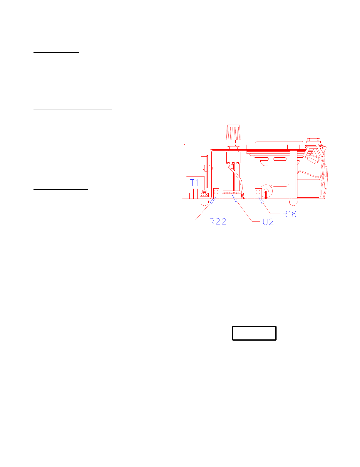
Figure 3.1. Tuning Components.
C. Set the Audio Oscillator to 37.5 kHz, with an output of
35 mvrms.
D. Monitoring the Audio Output Jack, adjust the TUNING
knob for peak signal at either the upper or lower peak. With
the GAIN pot at MAX, at least 1.5 Vrms should be ob-
served
E. Tune the slug of T1 for peak signal output. The response
will be very subtle. Locate adjustment T1 on Figure 3.3.
CAUTION
USE AN INSULATED TOOL TO MAKE THIS
ADJUSTMENT