JA-8
オフセットキャンセル有効時
測定範囲 10 kΩ~99.99 GΩ
(最大定格 500 VA の範囲にて )
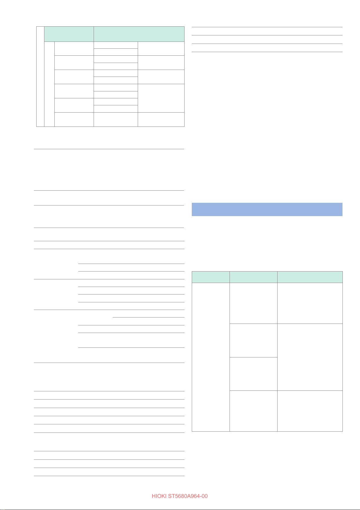
IR 確度
10 nA ≦I ≦3 µA 100 MΩ~999.9 MΩ±(30% of reading)*1,*2, *3
1.00 GΩ~99.99 GΩ
100 nA ≦I ≦30 µA 10.00 MΩ~99.99 MΩ±(25% of reading)*1,*2, *3
100.0 MΩ~999.9 MΩ
1 µA ≦I ≦300 µA 1.000 MΩ~9.999 MΩ±(22% of reading +
5 digit)*1,*2, *3
10.00 MΩ~99.99 MΩ
10 µA ≦I ≦3 mA 100.0 kΩ~999.9 kΩ
±(8.5% of reading +
3 digit)*1,*2, *3
1.000 MΩ~9.999 MΩ
100 µA ≦I ≦30 mA 10.00 kΩ~99.99 kΩ
100.0 kΩ~999.9 kΩ
1 mA ≦I ≦100 mA 10.00 kΩ~99.99 kΩ±(6% of reading +
3 digit)*1,*2, *3
*1:試験電圧が 50 V ~99 Vのとき測定確度に ±10% を加算
*2:試験電圧が 100 V ~999 Vのとき測定確度に ±5% を加算
*3:試験電圧が 1000 V ~2000 Vのとき測定確度に ±2% を加算
試験時間 設定範囲 0.1 s ~999 s 試験時間オフ
(TIMER OFF)機能あり
設定分解能 0.1 s ~99.9 s:0.1 s、100 s
~999 s:1 s
確度 ±(100 ppm + 20 ms)
初期設定 1.0 s
判定機能 上限基準値、下限基準値設定可
判定動作:UPPER FAIL、LOWER FAIL、PASS
その他の主な機能 波形グラフ表示、コンタクトチェック、オフセッ
トキャンセル、パネルメモリー機能、データメモ
リー機能
EXT. I/O
使用コネクター D-SUB 37 ピン メス 嵌合固定台ねじ #4-40
入力 フォトカプラー絶縁無電圧接点入力
(電流シンク/ソース出力対応)
入力 ON 残留電圧 1 V以下
入力OFF OPEN(遮断電流 100 µA 以下)
出力 フォトカプラー絶縁オープンドレイン出力(無極性)
最大負荷電圧 30 V
残留電圧 1 V以下
最大出力電流 50 mA/チャネル
電源出力 出力電圧 シンク出力時:5.0 V ±10%
ソース出力時:− 5.0 V ±10%
最大出力電流 100 mA
絶縁 保護接地電位および測定回路からフ
ローティング
対地間電圧 DC 50 V、AC 33 V rms、
AC 46.7 V peak以下
オプション
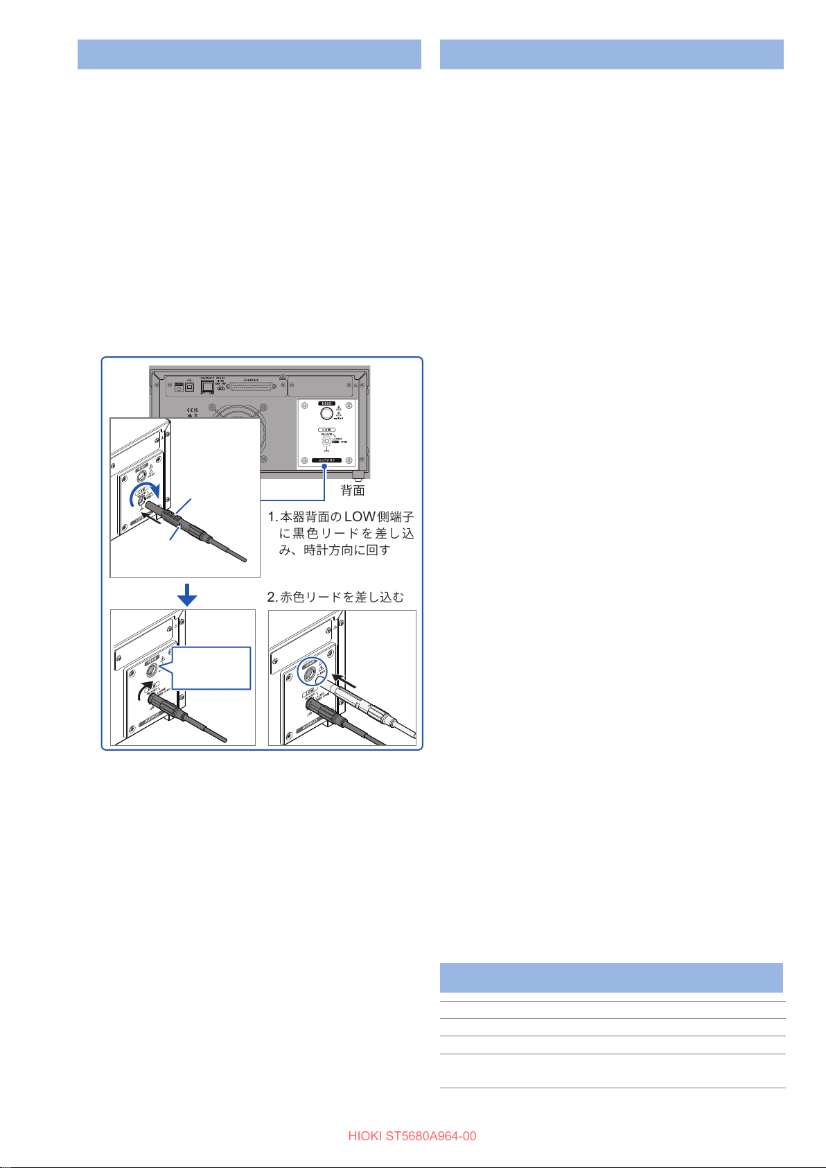
L2260 高圧テストリード
使用場所 屋内使用、汚染度 2、高度 2000 mまで
使用温湿度範囲 0°C ~40°C 80% RH以下(結露しないこと)
保存温湿度範囲 −10°C ~50°C 80% RH以下(結露しないこと)
最大定格電圧 AC 5000 V rms または DC 8000 V
最大定格電流 AC 1 A peak
L2261 加工用リード
使用場所 屋内使用、汚染度 2、高度 2000 mまで
使用温湿度範囲 0°C ~40°C 80% RH以下(結露しないこと)
保存温湿度範囲 −10°C ~50°C 80% RH以下(結露しないこと)
9613 片手用リモコン、9614 両手用リモコン
使用場所 屋内使用、高度 2000 mまで
使用温湿度範囲 0°C ~40°C 80% RH以下(結露しないこと)
保存温湿度範囲 −10°C ~50°C 90% RH以下(結露しないこと)
その他の仕様については、取扱説明書「14 仕様」をご覧ください。
機能仕様
(1) 耐電圧試験モード
参照:取扱説明書「4 耐電圧試験 /絶縁抵抗試験モード」
(2) 絶縁抵抗試験モード
参照:取扱説明書「4 耐電圧試験 /絶縁抵抗試験モード」
(3) W-IR/IR-W 試験モード
参照:取扱説明書「5 W-IR/IR-W試験モード」
(4) プログラムモード
参照:取扱説明書「6 プログラムモード」
(5) BDV 測定モード
参照:取扱説明書「7 BDV(絶縁破壊電圧)測定モード」
困ったときは
故障と思われるときは、「修理を依頼する前に」を確認してく
ださい。それでも問題が解決しない場合は、お買上店(代理店)
か最寄りの営業拠点にご連絡ください。
修理を依頼する前に
測定
症状 原因 対処方法
START ボタ
ンを押しても
試験が開始し
ない
START ボタンを
押す前にSTOP ボ
タンを押していな
い
本器は不用意な出力を避け
安全に試験を開始できる
ように、STOP ボタンと
START ボタンを使用した
2段階の操作が必要です。
EXT. I/O から
STOP信号が入力
されたままになっ
ている
START 信号はSTOP 信号
より優先順位が低いです。
START 時にはSTOP 信号
がOFF になるように変更
してください。
何らかの原因で
STOP ボタンが押
された状態になっ
ている
電圧制限値を超え
た電圧を設定して
いる
試験電圧と電圧制限値を確
認してください。試験電圧
が電圧制限値を超えた設定
になっていると試験が開始
しません。