2 … 4
WIRING
Preparation
•Reference the General Wiring Schematic on page 3.
•Disconnect all power to the valve proving system and the
flame safeguard before wiring to prevent electrical shock
and equipment damage.
• All wiring must comply with local electrical codes,
ordinances, and regulations.
• Do not exceed the terminal ratings given in the
specications.
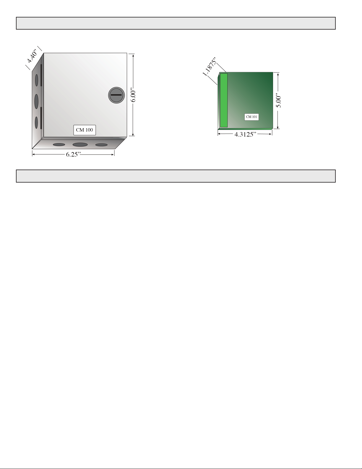
• Loosen the screw which secures the cover. (CM 100 only)
• Open the cover.
• Route the wires through the conduit connectors.
• Provide adequate strain relief.
Wiring
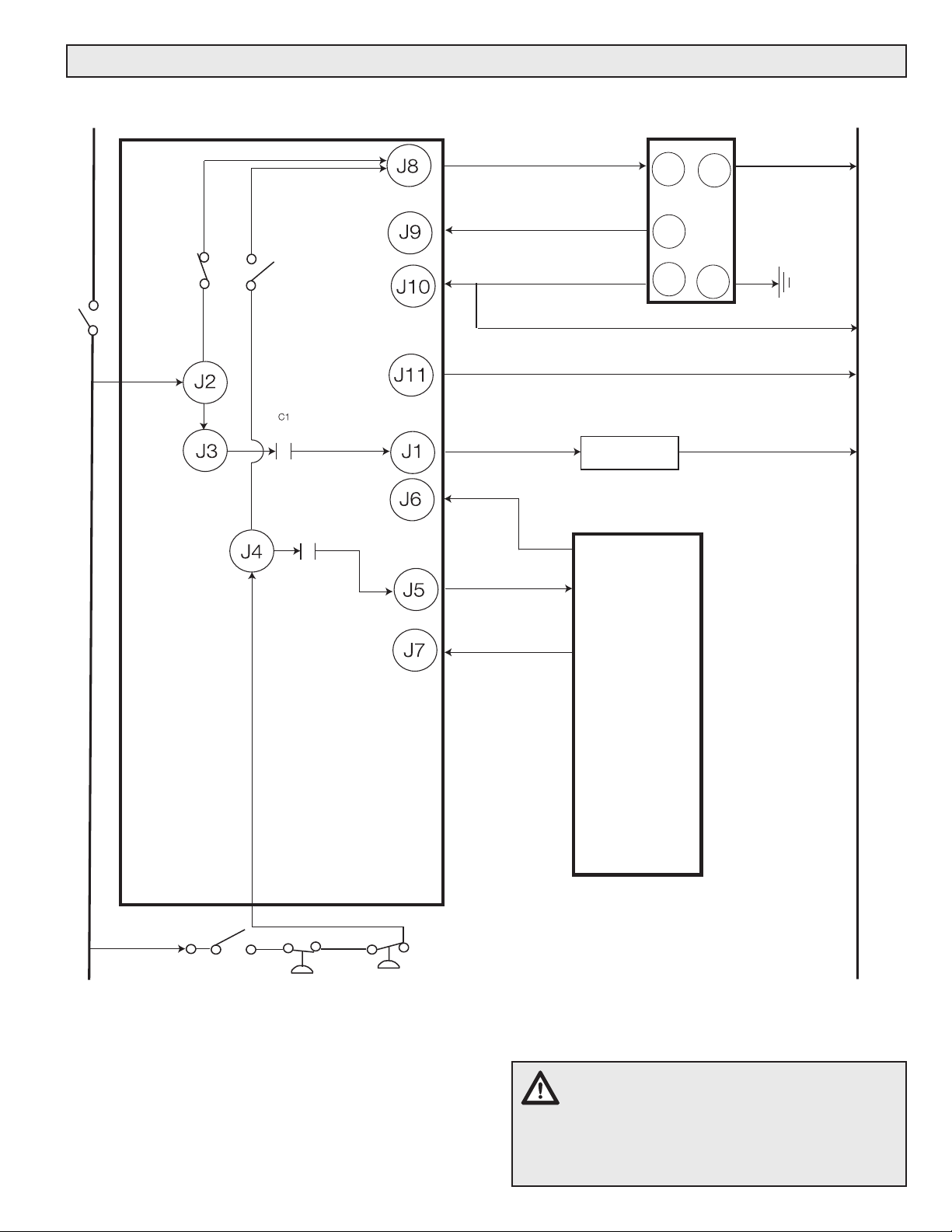
• A typical wiring diagram for operating a valve proving
system on burner start-up and after shutdown is shown in
the wiring diagram on page 2.
• If the blower is to be operated every time the valve
proving system detects an open valve, connect the blower
to J1, and the blower terminal of the flame safeguard to J6.
(The connection from the flame safeguard blower terminal
to J6 is required to provide proper operation of the blower
during a normal start-up procedure.) If the above is not
required, connect the blower directly to the flame safeguard
terminal and do not make the connection from the flame
safeguard blower terminal to J6. Terminal J1 can be used to
energize an alarm.
• NOTE: Frequency converters with insufcient
shielding can cause faults in the VPS 504/VDK 200A
as the result of transients. Verify that the equipment
is provided with sufcient shielding.
OPERATION
5 Safety Shutdown:
During a safety shutdown, the flame safeguard control en-
ergizes J7, which closes (if open) normally closed relay C2,
overrides the input to J4, and forces relay S2 to break and
then relay S1 to make. This resets the valve proving system.
If the valves are proved closed, J9 is energized and closes
C2 (or remains closed. If the valve proving fails, J10 will be
energized and C2 opens (or remains open).
6 Normal Shutdown:
On normal shutdown, J4 and subsequently J5 are deener-
gized when the “burner start” switch is opened. When J4
is de-energized, relay S2 breaks and then relay S1 makes,
which causes the valve proving system to reset and veri-
es the position of the two automatic shutoff valves. If the
valves are proved closed, J9 is energized and closes C2. If
the valve proving fails, J10 will be energized and C2 remains
open.
1 Initial Power:
When the main system is rst powered (L1) and there is no
call for heat, J2 gets powered, which allows power to J8.
When J8 gets energized. This applies 120Vac to the valve
proving system, which will cycle, verifying the automatic
shutoff valves position.
2 Valve Proving - Pass on initial system start.
If the valve proving system conrms that both automatic
shutoff valves are closed, it energizes terminal J9, which
closes normally open contact C2. If J7 from the flame
safeguarge is energzied, then energizing J9 does not close
C2.
3 Valve Proving - Pass on call for heat.
When there is a call for heat, terminal J4 is energized, which
then breaks relay S1 and then makes relay S2, even if J7
is energized. This restarts the valve proving system. If the
valve proven system energizes J9, C2 makesm, and power
is then applied to J5. The flame safeguard’s safety interlock
terminal is then energized, and the burner continues its igni-
tion sequence.
4 Valve Proving - Failure
If at anytime the valve proving system fails to prove the
automatic shutoff valve are closed, it energizes terminal J10,
which closes normally open relay C1. The blower turns on if
it is wired to J1 as shown in the wiring diagram. The internal
contact C2 remains opened, and J5 cannot be energized
even if J4 is energized; this prevents the burner system from
continuing with the ignition sequence.