Idle state: Valves 1 and 2 are closed.
Pressure build-up:The internal mo-
tor pump increases the gas pressure
in the test section by approx. 20 mbar
compared to the input-side pressure
applied to valve V1.
During the test period, the installed
dierential pressure switch monitors
the test section for leakage. If the test
pressure is attained, the motor pump
is switched o (end of test period). The
release time (10-34 s) depends on the
test volume (max. 8.0 l) and input pres-
sure (max. 500 mbar). If the test section
is tight, the contact is released to the
automatic burner control after max. 34
s - the yellow signal lamp lights up.
If the test section is leaky or if the pres-
sureincreaseby+20mbarisnot attained
during the test period (max. 34 s), the
VPS 508 switches to fault.The red signal
lamplightsas long as thecontactrelease
by the regulator or thermostat is present
(heat requirement).
If there is a short power failure during
the test or burner operation, the test
is started again automatically.
If the pumping time < approx. 10s,
the pressure dierence between the
testingsystemandtheinletpressureis
balanced after pumping is nished.
Operation: The internal valve of the
VPS 508 is closed.
Program sequence
Functional description
The VPS 508 operates depending on
pressure build-up.
Theprogrammodulestartstofunction
when heat is requested.
Test is performed depending on the
burner functional procedure:
Check prior to burner start or
Check during pre-purge period or
Check after burner shut-down
Function principle
Release period tF
Period which a VPS requires to per-
form a complete operation procedure.
The release period of the VPS 508
depends on test volume and input
pressure:
tF max. ≈ 34 s
Test period ttest
Pumping time of motor pump.
Test volume VTest
Volume between V1 output-side and
V2 input-side and the intermediate
tube pieces.
Vtest min. / VPS 508 = 1,5 l
Vtest max. / VPS 508 = 8 l
V1
p = 500 mbar
max.
V2
VPS 508
p
2
p
a
p
1
p
e
p
2
p
a
p
1
p
e
DMV-D(LE)
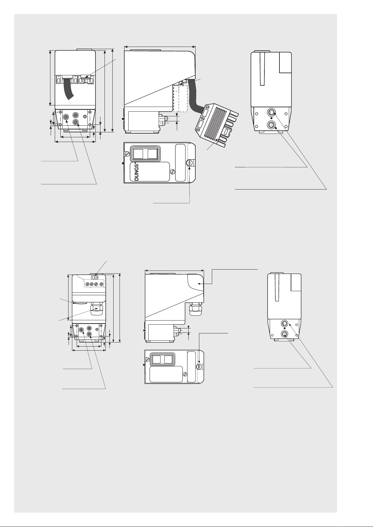
A
A Program module
Instrument gland
Connection
p + 20 mbar
e
V1
p = 500 mbar
max.
V2
VPS 508
p2
pa
p1
pe
p2
pa
p1
pe
Program
modul
p
e
V1
p = 500 mbar
max.
V2
VPS 508
p2
pa
p1
pe
p2
pa
p1
pe
Program
modul
p
e
V1
p = 500 mbar
max.
V2
VPS 508
p2
pa
p1
pe
p2
pa
p1
pe
Program
modul
p
e
p
e
p
e
p + 20 mbar
e
V1
p = 500 mbar
max.
V2
VPS 508
p
2
p
a
p
1
p
e
p
2
p
a
p
1
p
e
Program
modul
p
e
V1
p = 500 mbar
max.
V2
VPS 508
p
2
p
a
p
1
p
e
p
2
p
a
p
1
p
e
Program
modul
p
e
V1
p = 500 mbar
max.
V2
VPS 508
p
2
p
a
p
1
p
e
p
2
p
a
p
1
p
e
Program
modul
p
e
p
e
p
e
p + 20 mbar
e
V1
p = 500 mbar
max.
V2
VPS 508
p
2
p
a
p
1
p
e
p
2
p
a
p
1
p
e
Program
modul
p
e
V1
p = 500 mbar
max.
V2
VPS 508
p
2
p
a
p
1
p
e
p
2
p
a
p
1
p
e
Program
modul
p
e
V1
p = 500 mbar
max.
V2
VPS 508
p
2
p
a
p
1
p
e
p
2
p
a
p
1
p
e
Program
modul
p
ep
ep
e
Operation
Idle state Pressure
build-up
Field of application
Test volume
Vprüf [l]
Release period
23456 7 81
4
2
6
8
10
12
14
16
18
20
22
24
26
28
30
32
34
p
1
/p
e
= 100 mbar
p
1
/p
e
=
20 mbar
p
1
/p
e
= 200 mbar
p
1
/p
e
= 300 mbar
p
1
/p
e
= 500 mbar
tF [s]