DUNIWAY Stockroom Terranova 752A User manual

TELEPHONE: 650-969-8811
TOLL-FREE (US/Canada): 800-446-8811
FAX: 650-965-0764
EMAIL: info@duniway.com
WEB: www.duniway.com
2of 38
TABLE OF CONTENTS
SPECIFICATIONS 3
ACCESSORIES 4
INTRODUCTION 5
INSTALLATION 5
OPERATION 8
Self-Test 8
Setup Mode 8
Disabling the Control Unit Speaker 9
Power Loss Restart 10
Restoring Default Values 11
MODE OF OPERATION 11
ION PUMP OPERATION 13
Start Phase 13
Normal Operation 15
Cool-down Mode 15
Shutdown Mode 16
SET POINT OPERATION 16
ANALOG OUTPUT 19
SERIAL COMMUNICATION 20
TROUBLESHOOTING 26
INTERNAL DIP SWITCH SETUP 28
CHANGING HIGH VOLTAGE POLARITY 29
CHANGING FUSES 32
LEGACY TERRANOVA® 752 33
WARRANTY 33
DECLARATION OF CONFORMITY 34
APPENDIX 1. COMPATIBLE DUNIWAY ION PUMP CABLES 35
APPENDIX 2. NOTES ON TERRANOVA® SET POINT RELAYS 36

TELEPHONE: 650-969-8811
TOLL-FREE (US/Canada): 800-446-8811
FAX: 650-965-0764
EMAIL: info@duniway.com
WEB: www.duniway.com
3of 38
Specifications
Operating Voltage
Universal
100 V to 120 V AC @ 50 Hz to 60 Hz; 100 VA
Open Circuit Voltage
Operator Set
± 3500 V to ± 7500 V DC
Polarity
Positive (Default) / Negative
Short Circuit Current
Operator Set
50 mA maximum per channel
High Voltage Output
Options
Two 10 kV Kings connectors
Two Fischer-style connectors
Overload Protection
Fuse for line power
Automatic power adjustment during Start Phase
Automatic shutdown for shorted output
Display
Voltage
4 Red LEDs –3 digits & polarity (±X.XX)
Current
4 Red LEDs –3 digits (XXX) with unit auto-range
Pressure
4 Red LEDs –2 digits with exponent (X.X -X)
Pressure Units
Torr (Default)
mbar
Pascal
Relay Rating
Varies
From:
2 A at 30 V DC (60 V AC)
To:
0.4 A at 150 V DC (300 V AC)
See Appendix 2 for more details
Dimensions
Height:
3.5 in. (88 mm)
Width:
9.5 in. (240 mm)
Length:
16.0 in. (405 mm)
Weight
6 lb. / 2.7 kg

TELEPHONE: 650-969-8811
TOLL-FREE (US/Canada): 800-446-8811
FAX: 650-965-0764
EMAIL: info@duniway.com
WEB: www.duniway.com
4of 38
Accessories
Included
Instruction manual (Online)
One power cord
Two replacement fuses
One unterminated male 9-pin D-sub connector
One unterminated male 15-pin D-sub connector
One unterminated male 25-pin D-sub connector
Required
(Sold separately)
See Appendix 1 for a list of compatible ion pump cables
Optional
RS232-TN751A
RS-232 serial communication cable (10 ft.)*
8000-0934-00
Half rack adapter kit for single control unit
8000-0934-01
Rack adapter kit for two control units
10KV-100M
Test plug
* Custom cable lengths available upon request
Terranova® 752A Control Unit Options
Part No.
Description
T-752A-K110*
Two 10 kV Kings Connectors (110 V AC)
T-752A-F110*
Two Fischer-style Connectors (110 V AC)
*Specify polarity at time of purchase;
220 V AC operation also available
High Voltage
Bodily harm or equipment damage can result due to electric shock
originating from the input AC voltage, internal unit potentials, or
high voltage output. The high voltage output hazard can exist
either from direct contact with the high voltage lead or due to loss
or lack of proper grounding from either the Terranova® 752A or
ion pump. User should wait at least 15 seconds after turning OFF
the high voltage before working on the control unit or ion pump.

TELEPHONE: 650-969-8811
TOLL-FREE (US/Canada): 800-446-8811
FAX: 650-965-0764
EMAIL: info@duniway.com
WEB: www.duniway.com
5of 38
Introduction
The Terranova® 752A Dual Ion Pump Power Supply is designed to independently start and
operate two ion pumps from a number of manufacturers. With user-changeable high voltage
polarity, the Terranova® 752A can operate either positive or negative pump element
configurations.
Installation
Mounting the Terranova® 752A
The Terranova® 752A is housed in a standard EIA half-rack box to allow for mounting on most
equipment racks / cabinets. See Figure 1 for control unit dimensions. A half rack adapter kit for
a single control unit, item 8000-0934-00, and a rack adapter kit for two control units, item
8000-0934-01, are available to mount the Terranova® 752A to 19” equipment racks. User
should leave enough clearance at time of installation to both access rear cable connections and
for ventilation purposes.
Figure 1. Terranova® 752A dimensions
Connecting the Ion Pump
The Terranova® 752A has either two 10 kV Kings connectors or two Fischer-style connectors
located on the back of the control unit labeled HIGH VOLTAGE OUT. User will require a Duniway
or equivalent ion pump cable to connect the ion pump(s) to the control unit. See Appendix 1
for a list of compatible ion pump cables.

TELEPHONE: 650-969-8811
TOLL-FREE (US/Canada): 800-446-8811
FAX: 650-965-0764
EMAIL: info@duniway.com
WEB: www.duniway.com
6of 38
WARNING
Use of cables other than those approved by Duniway Stockroom
Corp. could lead to operation problems or safety hazards.
Figure 2. Terranova® 752A back view
To properly connect the Terranova® 752A to the ion pump(s):
1. Secure the ion pump cable end to the ion pump high voltage feedthrough(s)
2. Secure the ion pump cable to the respective HIGH VOLTAGE OUT connector
3. Secure the required secondary ground sense lead(s) to both the ion pump body
and respective GROUND SENSE stud (see Safety Interlock Feature)
WARNING
NEVER apply power to the Terranova® 752A until proper
grounding has been established.
User should always ensure the ion pump and high voltage cable are properly connected and
secured before use.

TELEPHONE: 650-969-8811
TOLL-FREE (US/Canada): 800-446-8811
FAX: 650-965-0764
EMAIL: info@duniway.com
WEB: www.duniway.com
7of 38
Safety Interlock Feature
A safety interlock or secondary ground sense circuit is incorporated into each channel of the
Terranova® 752A to disable high voltage operation when open. The safety interlock circuit is
completed via an external lead available on most Duniway ion pump cables. The external lead
must properly connect the ion pump body to the respective GROUND SENSE stud of the control
unit (see Figure 2) to complete the safety interlock circuit and enable high voltage operation.
High voltage output will be disabled on the respective channel if an open circuit or ground fault
is detected. Both the HIGH VOLT INTERLOCK IS OPEN and selected pressure unit LED will
illuminate for the respective channel if the safety interlock circuit is open. To restart high
voltage operation, user must correct the grounding issue. Table 1 lists various ground sense
connection conditions and effects on high voltage operation.
Case
Primary
(Cable Shielding)
Safety
Interlock
Redundant*
High Voltage
Operation
1
N
N
N
OFF
2
Y
N
N
OFF
3
N
Y
N
OFF
4
N
N
Y
OFF
5
Y
Y
N
ON
6
Y
N
Y
OFF
7
N
Y
Y
ON
8
Y
Y
Y
ON
Table 1. Terranova® 752A Ground Sense Conditions
*A redundant ground connection, either intentional or unintentional, between the control unit
and ion pump may circumvent the safety interlock feature. User should correct any grounding
issues to ensure safe operation. A potential (unintentional) redundant ground may occur
through chassis contact with the ion pump or vacuum system ground when both the ion
pump and Terranova® 752A are mounted on the same conducting rack or cart.
WARNING
Under no circumstances should the safety interlock lead be
connected directly to the Terranova® 752A case. This would
defeat the protection provided by this safety interlock feature and
may result in serious electrical shock.

TELEPHONE: 650-969-8811
TOLL-FREE (US/Canada): 800-446-8811
FAX: 650-965-0764
EMAIL: info@duniway.com
WEB: www.duniway.com
8of 38
Operation
Self-Test
The Terranova® 752A will perform a self-test at power ON. Each step is initiated by a BEEP
sound in the following sequence:
1. All display segments become illuminated for CHANNEL 1
2. All LED indicators (except HV ON/OFF and HIGH VOLT INTERLOCK IS OPEN)
become illuminated for CHANNEL 1
3. Steps 1 and 2 repeat for CHANNEL 2
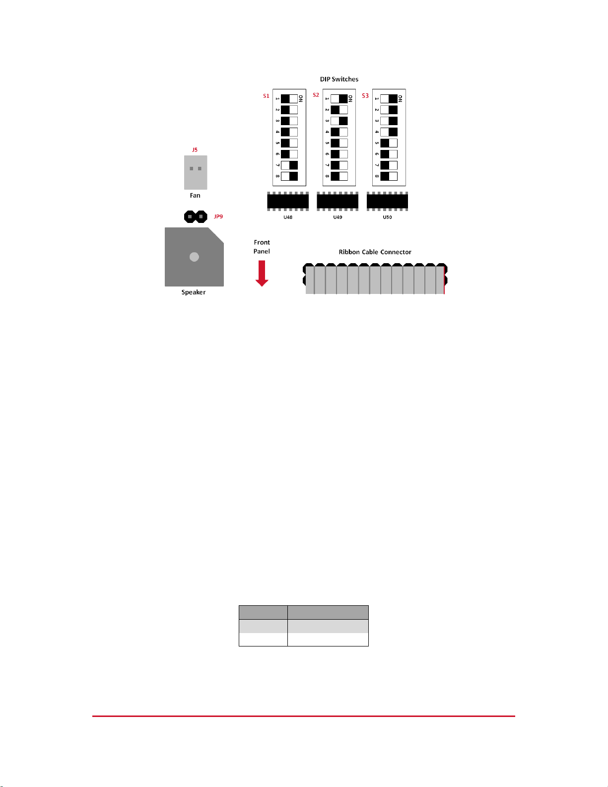
4. CHANNEL 1 CURRENT display reads DIP switch code (e.g. 0FC0)
See Internal DIP Switch Setup
CHANNEL 1 PRESSURE display reads the firmware version (e.g. 1.82);
CHANNEL 2 CURRENT display reads RS-485 address (e.g. 5)
See Changing the RS-485 Address
CHANNEL 2 PRESSURE display reads the model number (e.g. 752A)
The Terranova® 752A will enter Standby Mode if Self-Test is successful. In Standby Mode, the
HIGH VOLTAGE display will read OFF and the LED corresponding to the default or user-selected
pressure unit will become illuminated. The control unit fan will automatically start at power ON.
An RS-485 address will be output regardless of selected communication standard.
Setup Mode
Terranova® 752A unit parameters for CHANNEL 1 or CHANNEL 2 can be set or modified by the
following six-step operation:
1. Press the SELECT button to set or adjust the SET POINT pressure value. Use the
RAISE or LOWER button to increase or decrease the pressure value shown on the
PRESSURE display. Pressure range is from 0.1 x 10⁻⁹ to 1.0 x 10⁻⁵ in the selected
units of pressure. Default value is OFF. PRESSURE display, respective pressure
unit LED, and SET POINT LED will illuminate during adjustment. See Set Point
Operation
2. Press the SELECT button a second time to adjust the maximum high voltage
supplied by the control unit. Use the RAISE or LOWER button to increase or
decrease the MAX VOLTAGE value shown on the HIGH VOLTAGE display. Voltage
range is from 3.50 kV to 7.00 kV in 0.5 kV steps. Default voltage is 7.50 kV. MAX
VOLTAGE LED will illuminate during adjustment.
3. Press the SELECT button a third time to adjust the maximum current limit of the
control unit. Use the RAISE or LOWER button to increase or decrease the MAX
CURRENT value shown on the CURRENT display. Current range is from 1 mA to
50 mA. Default current is 10 mA. CURRENT display, respective current unit LED,
and MAX CURRENT LED will illuminate during adjustment.

TELEPHONE: 650-969-8811
TOLL-FREE (US/Canada): 800-446-8811
FAX: 650-965-0764
EMAIL: info@duniway.com
WEB: www.duniway.com
9of 38
4. Press the SELECT button a fourth time to set or adjust the ion pump speed. Use
the RAISE or LOWER button to increase or decrease the PUMP SIZE value shown
on the CURRENT display. Pump speed range is from 0.1 L/s to 999 L/s. Default
pumping speed is 20 L/s. CURRENT display and PUMP SIZE LED will illuminate
during adjustment
PUMP SIZE value and CURRENT display value are used to calculate
the pressure shown on the PRESSURE display
5. Press the SELECT button a fifth time to set the proper pressure unit. Use the
RAISE or LOWER button to select the proper PRESSURE UNITS value shown on
the PRESSURE display. User can select between torr, millibar, and Pascal
pressure units. Default pressure unit is Torr. PRESSURE display, respective
pressure LED and PRESSURE UNITS LED will illuminate during adjustment.
6. Press the SELECT button a sixth time to return the unit to Standby mode.
A BEEP will be emitted with each SELECT button depression. All display segments will
momentarily illuminate during the Setup to Standby Mode transition. The unit will return to
Standby Mode if left unattended for approximately 60 seconds during Setup Mode. Any
parameter changes will be saved. If the unit is turned OFF during the Setup Mode, modified
parameters will revert to previous values.
Disabling the Control Unit Speaker
User may disable the control unit speaker in the event BEEP noises become an annoyance. To
disable the Terranova® 752A speaker:
1. Turn the unit OFF via the POWER switch
2. Remove the power cord and ion pump cable
3. Remove the six screws along the edge of the top cover
4. Carefully lift the top cover and disconnect the fan plug
5. Remove top cover
6. Locate jumper JP9 –see Figure 3
7. Remove the 2-pin shunt jumper from jumper JP9
8. Connect the fan plug and replace top cover
9. Connect the ion pump cable and power cord
10. Restart the unit via the POWER switch

TELEPHONE: 650-969-8811
TOLL-FREE (US/Canada): 800-446-8811
FAX: 650-965-0764
EMAIL: info@duniway.com
WEB: www.duniway.com
10 of 38
Figure 3. DIP switch and JP9 jumper location
Power Loss Restart
The Terranova® 752A may be set to automatically restart high voltage operation after a power
outage. If high voltage was enabled before the interruption, high voltage operation will
commence –first on CHANNEL 1, then CHANNEL 2 –once power to the control unit is restored.
The safety interlock circuit must remain closed throughout the entire process for a successful
power loss restart. The automatic restart function is by default disabled. To enable the power
loss restart:
1. Turn the unit OFF via the POWER switch
2. Remove the power cord and ion pump cable
3. Remove the six screws along the edge of the top cover
4. Carefully lift the top cover and disconnect the fan plug
5. Remove top cover
6. Locate DIP Switch S1-2 –see Figure 3
7. Set DIP Switch S1-2 to the ON position according to Table 2
8. Connect the fan plug and replace top cover
9. Connect the ion pump cable and power cord
10. Restart the unit via the POWER switch
Restart
DIP Switch S1-2
Disabled
OFF
Enabled
ON
Table 2. DIP Switch S1-2 state
Once the Terranova® 752A is powered ON, the unit will commence the Self-Test. Thereafter,
the control unit will resume normal operation.

TELEPHONE: 650-969-8811
TOLL-FREE (US/Canada): 800-446-8811
FAX: 650-965-0764
EMAIL: info@duniway.com
WEB: www.duniway.com
11 of 38
Restoring Default Values
Restoring default parameters provides a starting point for control unit readjustment in the
event measurements become unreliable. Each Terranova® 752A channel may be independently
restored to default values. To restore default values:
1. Turn the unit OFF via the POWER switch
2. Simultaneously depress the SELECT button for the channel to be restored along
with the RAISE and LOWER buttons and restart the unit via the POWER switch
Once power is restored, the unit will commence the Self-Test. If reset is successful, the code
RST will appear on the CURRENT display of the respective channel followed by short BEEPs.
User should release all three buttons after the code RST has been output to resume normal
operation. Otherwise, error code ER9 will be output to the CURRENT display of CHANNEL 1 –
this is normal. Error code ER9 will also be output after an unsuccessful reset. If code RST is not
output, user should repeat the reset sequence since all three buttons were not fully or
simultaneously depressed.
Mode of Operation
The Terranova® 752A has three different user-selectable operation modes: Mode 0 (default),
Mode 1, and Mode 2. In all three modes, high voltage operation may be controlled through the
HIGH VOLTAGE ON/OFF button of each respective channel or via serial communication. The
HIGH VOLTAGE ON/OFF button must be depressed for more than two seconds for high voltage
operation to commence. The respective HIGH VOLTAGE ON/OFF LED will become illuminated
when high voltage operation commences.
To avoid erroneous transient values, CURRENT and PRESSURE
displays will not immediately output readings after high voltage
operation is commenced.
The Terranova® 752A mode of operation may be changed via an internal DIP switch, DIP Switch
S1, located towards the front panel of the control unit. Although DIP Switch S1 has eight
individual ON/OFF switches labeled S1-1 to S1-8, only DIP Switch S1-1 and DIP Switch S1-2 are
utilized. To change the mode of operation:
1. Turn the unit OFF via the POWER switch
2. Remove the power cord and ion pump cable
3. Remove the six screws along the edge of the top cover
4. Carefully lift the top cover and disconnect the fan plug
5. Remove top cover
6. Locate DIP Switch S1 –see Figure 3
7. Set individual switches to desired mode of operation according to Table 3
8. Connect the fan plug and replace top cover
9. Connect the ion pump cable and power cord
10. Restart the unit via the POWER switch

TELEPHONE: 650-969-8811
TOLL-FREE (US/Canada): 800-446-8811
FAX: 650-965-0764
EMAIL: info@duniway.com
WEB: www.duniway.com
12 of 38
Mode
DIP Switch S1-3
DIP Switch S1-4
0
OFF
OFF
1
ON
OFF
2
OFF
ON
Table 3. DIP Switch Mode Selection
Mode 0: Standard Operation
Terranova® 752A operation and parameter input may be conducted either via the front panel
buttons or serial communication. Default mode of operation at time of shipment.
Mode 1: Secondary Interlock
Terranova® 752A operation and parameter input may be conducted either via the front panel
buttons or serial communication. However, high voltage operation becomes dependent on a
secondary interlock in addition to the safety interlock circuit of each channel. The secondary
interlock is based on the output voltage level of an internal +5 V TTL circuit output via PIN 8 of
the MISCELLANEOUS I/O port or PIN 13 of the AUXILIARY I/O port for CHANNEL 1 and PIN 10 of
the AUXILIARY I/O port for CHANNEL 2. To commence high voltage operation on a respective
channel, the safety interlock circuit must be closed and the output voltage level of the
secondary interlock must be held LOW. High voltage operation will be interrupted if an open
circuit or ground fault is detected or if the TTL output voltage level is HIGH. If user attempts to
start high voltage operation with the second interlock circuit open, error code ER6 will be
output on the CURRENT display of the respective channel.
Mode 2: TTL High Voltage Operation
Terranova® 752A high voltage operation may be controlled manually through the HIGH
VOLTAGE ON/OFF button and remotely either via serial communication or using output voltage
levels of an internal +5 V TTL circuit for each channel. TTL circuit voltage output may be
accessed through PIN 8 of the MISCELLANEOUS I/O port or PIN 13 of the AUXILIARY I/O port for
CHANNEL 1 and PIN 10 of the AUXILIARY I/O port for CHANNEL 2. High voltage operation will
commence at a rising edge after output voltage level is LOW for more than 2 seconds. High
voltage operation will be interrupted at a falling edge soon after output voltage level is LOW for
more than 0.2 seconds.
In Mode 2, all control unit parameters must be set or changed via serial communication. User
may only scroll through unit parameters via the SELECT button. If user attempts to change
parameters via the front panel, error code ER4 will be output on the CURRENT display of the
respective channel. To change unit parameters via the front panel, the Terranova® 752A must
enter a special setup mode.

TELEPHONE: 650-969-8811
TOLL-FREE (US/Canada): 800-446-8811
FAX: 650-965-0764
EMAIL: info@duniway.com
WEB: www.duniway.com
13 of 38
To access the special setup mode:
1. Turn the control unit OFF via the POWER button
2. Depress the SELECT button for CHANNEL 1 and restart the control unit via the
POWER switch
If successful, the HIGH VOLTAGE display for CHANNEL 1 will output the code SU. Soon after, the
HIGH VOLTAGE displays will output the code OFF and SU for CHANNEL 1 and CHANNEL 2,
respectively. Thereafter, parameters may be changed via the front panel buttons. To return the
Terranova® 752A to normal operation, user must restart the control unit via the POWER
button.
Ion Pump Operation
The Terranova® 752A can start most new ion pumps that possess pumping speeds of up to
100 L/s at pressures as high as 1 x 10⁻³ Torr. Larger ion pumps with higher current requirements
or heavily-used ion pumps may also be started with the Terranova® 752A, but at lower
pressures. See Table 4for recommended starting pressure for a number of ion pumps.
However, once an ion pump is started, the Terranova® 752A is able to maintain normal
operation for all compatible units.
Pumping Speed [L/s]
Pressure [Torr]
400 - 500
5 x 10⁻⁵
220 - 270
1 x 10⁻⁴
110 - 140
3 x 10⁻⁴
60
5 x 10⁻⁴
≥ 30
1 x 10⁻³
Table 4. Recommended ion pump starting pressures
Start Phase
To operate an ion pump with the Terranova® 752A, system pressure must be less than the
recommended values on Table 4. Once high voltage operation is commenced, user should
observe the HIGH VOLTAGE and CURRENT display values. If high voltage increases to the MAX
VOLTAGE value and current approximates 0 µA, the ion pump has successfully started –the
Terranova® 752A and ion pump have entered normal operation. Decreasing current and
increasing high voltage values are an indication of a successfully started ion pump.

TELEPHONE: 650-969-8811
TOLL-FREE (US/Canada): 800-446-8811
FAX: 650-965-0764
EMAIL: info@duniway.com
WEB: www.duniway.com
14 of 38
Figure 4. Terranova® 752A Power vs. Current relationship
Figure 5. Terranova® 752A Voltage vs. Current relationship
However, if high voltage output does not appear to increase, the ion pump / vacuum system is
still at too high of a pressure. User should terminate high voltage operation and further pump
on the ion pump / vacuum system. Once a lower vacuum pressure is achieved, high voltage
operation should be restarted. As shown in Figure 4, current and thus, power, is highest during
the starting phase of an ion pump.
If high voltage output increases or remains constant as current decreases, user should isolate
the ion pump / chamber from the roughing system to help start the ion pump. If this isolation
leads to an increase in current, user should terminate high voltage operation and continue
pumping on the ion pump / vacuum system. Once a lower vacuum pressure is achieved, high
voltage operation should be restarted. Otherwise, the ion pump / chamber should remain
isolated; user should observe current and high voltage values for normal operation.
An increase in vacuum pressure may be observed during the starting phase of an ion pump. The
increase in pressure is due to outgassing of previously-absorbed atoms and molecules caused
by internal pump heating. Outgassing is beneficial as it helps reduce the gas load.

TELEPHONE: 650-969-8811
TOLL-FREE (US/Canada): 800-446-8811
FAX: 650-965-0764
EMAIL: info@duniway.com
WEB: www.duniway.com
15 of 38
Normal Operation
Once the ion pump has been successfully started, Terranova® 752A operation is almost
automatic. As shown in Figure 5, high voltage will approach the open circuit value (i.e. MAX
VOLTAGE value) as current output approximate 0 µA. Current units will auto range during use
as ion pump current increases or decreases.
Pressure Measurement
The Terranova® 752A outputs pressure measurements based on the ion pump current shown
on the CURRENT display of each channel. Once an ion pump reaches Normal Operation, current
becomes nearly proportional to vacuum pressure over a wide range of pressure values. If the
proper pump size (i.e. pumping speed) has been selected, pressure at the ion pump inlet may
be read from the respective PRESSURE display. The following equation is used to approximate
the pressure Pin torr:
.
where Kis an experimentally-determined constant equal to 370, Iis current in amperes, Sis the
pumping speed of the ion pump (i.e. PUMP SIZE value) in liters per second, and Vis the high
voltage (MAX VOLTAGE value) in volts. For example, if the MAX VOLTAGE value is set to 6.00 kV
and the PUMP SIZE value is set to 100 L/s, V= 6000 V and S= 100 L/s. Therefore, if the current
reading on the CURRENT display is 1.0 mA (or 1.0 x 10⁻³ A), Pis approximately 6.2 x 10⁻⁷ Torr.
Current measurements can also be used to determine pressure if the ion pump current-
pressure relationship is known. However, ion pump pressure readings should only be taken as
an approximation and not a reliable indication of system pressure. A separate pressure gauge
(e.g. ionization gauge) is strongly recommended for a more accurate pressure measurement.
Cool-down Mode
If the ion pump current is at or near the MAX CURRENT value, the Terranova® 752A will reduce
the high voltage applied to the ion pump for said channel. This can occur if user selects too low
of a MAX CURRENT value for the selected ion pump. The decrease in voltage output will
continue until current output is significantly less than the MAX CURRENT value. The control unit
decreases power output to protect the ion pump –especially small pumps –from possible
damage. If current output or power is not significantly reduced within a 10-minute period, the
respective channel will enter a cool-down cycle.
If both high voltage supplies exceed a total power of approximately
65 W during operation, high voltage output for both channels will be
temporarily decreased

TELEPHONE: 650-969-8811
TOLL-FREE (US/Canada): 800-446-8811
FAX: 650-965-0764
EMAIL: info@duniway.com
WEB: www.duniway.com
16 of 38
If a channel enters the Cool-down Mode, a BEEP will be emitted followed by the code CD1 to
indicate the first of five OFF/ON states. During these cycles, high voltage operation is
automatically disabled for five minutes (i.e. OFF period) and enabled for 10 minutes (i.e. ON
period). If the ion pump current is not reduced during the ON period, the unit will commence
the next OFF/ON cycle. The control unit will emit X number of BEEPs –if the speaker is not
disabled –and output the code CDX onto the corresponding CURRENT display, where X is the
cycle number, to indicate the start of the corresponding OFF/ON cycle. If current is significantly
reduced at any time during an ON period, the channel will exit the Cool-down Mode and
resume normal operation. However, if current is not reduced by the end of the OFF period of
the fifth cycle, the channel will automatically enter the Shutdown Mode and output the code
SD5 onto the respective CURRENT display.
Shutdown Mode
A channel will enter the Shutdown Mode if current output is not successfully reduced during
the cool-down cycles. The channel will also enter the Shutdown Mode if high voltage output is
shorted to ground or power output remains relatively high. This can occur either through a
malfunction of the ion pump or ion pump cable. When a channel enters a shutdown state, high
voltage operation is disabled, a five-second BEEP is emitted –if the speaker has not been
disabled –and the code SD will be output onto the respective CURRENT display. To recover
from a shutdown, high voltage operation may only be restarted via the respective
HIGH VOLTAGE ON/OFF button.
User cannot recuperate from a shutdown state via remote operation
Set Point Operation
The Terranova® 752A can be utilized for process control functions through the use of two
independent, programmable set points and corresponding relays –i.e. CHANNEL 1 SET POINT
and CHANNEL 2 SET POINT. Set point pressure values may be adjusted either through the front
panel or serial communication; relay output is accessible through both the MISCELLANEOUS I/O
or AUXILIARY I/O ports for CHANNEL 1 and AUXILIARY I/O port for CHANNEL 2. See Table 5 and
Table 6 for relay pin configuration.
The relay will activate once the pressure reading is less than or equal to the SET POINT value for
each respective channel. The SET POINT LED for the respective channel will become illuminated
once the relay is active. The relay will deactivate once the pressure reading is greater than or
equal to 20% of the respective SET POINT value. The relay deactivation pressure value can be
determined by the following
S+ 0.2*S

TELEPHONE: 650-969-8811
TOLL-FREE (US/Canada): 800-446-8811
FAX: 650-965-0764
EMAIL: info@duniway.com
WEB: www.duniway.com
17 of 38
in which Sis the set point value in the selected pressure unit. For example, if the SET POINT is
1.0 * 10-8 Torr, the relay will activate once the pressure reading is less than or equal to
1.0 * 10-8 Torr and deactivate once the pressure reading is greater than or equal to
1.2 * 10-8 Torr. If the set point value is OFF, the relay will be disabled. The Terranova® 752A set
point pressure display resolution is in 0.1 steps per pressure decade (or order of magnitude) in
torr units. Display resolution is converted from torr to millibar or Pascal units. See Appendix 2
for relay use with inductive or capacitive load switching.
PIN
Function
Output
Description
1
CHANNEL 1 SET POINT Relay
Common
See Set Point Operation
2
CHANNEL 1 SET POINT Relay
Normally closed (NC)
See Set Point Operation
3
Earth Ground
4
Digital Ground
5
Voltage Output
-15 V
See NOTES
6
Voltage Output
+15 V
See NOTES
7
Voltage Output
+5 V
See NOTES
8
CHANNEL 1 TTL Output
+5 V
See Mode of Operation
9
CHANNEL 1 SET POINT Relay
Normally open (NO)
See Set Point Operation
10
Voltage Output
+12 V
See NOTES
11
CHANNEL 1 SET POINT Relay Sense
+5 V
See NOTES
12
CHANNEL 1 Current Analog Output
See Analog Output
13
CHANNEL 1 HV (-) Sense
+12 V
See NOTES
14
CHANNEL 1 HV Analog Output
See Analog Output
15
CHANNEL 1 HV (+) Sense
+12 V
See NOTES
Table 5. MISCELLANEOUS I/O port pin configuration
NOTES
PIN 5, 6, 10 Nominal output available for external use. Current limit: 0.2 A.
PIN 7 Nominal output available for external use. Current limit: 0.2 A.
(Same as PIN 12 of the AUXILIARY I/O port)
PIN 11 Nominal output available when CHANNEL 1 set point relay is
active.
PIN 13 Nominal output available during CHANNEL 1 high voltage
operation if high voltage polarity is negative.
PIN 15 Nominal output available during CHANNEL 1 high voltage
operation if high voltage polarity is positive.

TELEPHONE: 650-969-8811
TOLL-FREE (US/Canada): 800-446-8811
FAX: 650-965-0764
EMAIL: info@duniway.com
WEB: www.duniway.com
18 of 38
PIN
Function
Output
Description
1
CHANNEL 1 SET POINT Relay
Common
See Set Point Operation
2
CHANNEL 1 SET POINT Relay
Normally closed (NC)
See Set Point Operation
3
CHANNEL 1 SET POINT Relay Sense
+5 V
See NOTES
4
CHANNEL 2 SET POINT Relay
Common
See Set Point Operation
5
CHANNEL 2 SET POINT Relay
Normally closed (NC)
See Set Point Operation
6
N/A
N/A
N/A
7
N/A
N/A
N/A
8
CHANNEL 2 Current Analog Output
See Analog Output
9
CHANNEL 2 HV Analog Output
See Analog Output
10
CHANNEL 2 TTL Output
+5 V
See Mode of Operation
11
CHANNEL 1 HV (-) Sense
+12 V
See NOTES
12
Voltage Output
+5 V
See NOTES
13
CHANNEL 1 TTL Output
+5 V
See Mode of Operation
14
CHANNEL 1 SET POINT Relay
Normally open (NO)
See Set Point Operation
15
Earth Ground
16
Digital Ground
17
CHANNEL 2 SET POINT Relay
Normally open (NO)
See Set Point Operation
18
CHANNEL 2 SET POINT Relay Sense
+5 V
See NOTES
19
N/A
N/A
N/A
20
N/A
N/A
N/A
21
CHANNEL 2 HV (-) Sense
+12 V
See NOTES
22
CHANNEL 2 HV (+) Sense
+12 V
See NOTES
23
CHANNEL 1 Current Analog Output
See Analog Output
24
CHANNEL 1 HV Analog Output
See Analog Output
25
CHANNEL 1 HV (+) Sense
+12 V
See NOTES
Table 6. AUXILIARY I/O port pin configuration
NOTES
PIN 3 Nominal output available when CHANNEL 1 set point relay is active.
PIN 11 Nominal output available during CHANNEL 1 high voltage operation if
high voltage polarity is negative.
PIN 12 Nominal output available for external use. Current limit: 0.2 A.
(Same as PIN 7 of the MISCELLANEOUS I/O port)
PIN 18 Nominal output available when CHANNEL 2 set point relay is active.
PIN 21 Nominal output available during CHANNEL 2 high voltage operation if
high voltage polarity is negative.
PIN 22 Nominal output available during CHANNEL 2 high voltage operation if
high voltage polarity is positive.
PIN 25 Nominal output available during CHANNEL 1 high voltage operation if
high voltage polarity is positive.
All CHANNEL 1 AUXILIARY I/O port outputs are the same as CHANNEL 1
MISCELLANEOUS I/O port outputs.

TELEPHONE: 650-969-8811
TOLL-FREE (US/Canada): 800-446-8811
FAX: 650-965-0764
EMAIL: info@duniway.com
WEB: www.duniway.com
19 of 38
Analog Output
The Terranova® 752A has analog output available for use as a secondary method to read the
high voltage and current values shown on the HIGH VOLTAGE and CURRENT display,
respectively, of each channel. The unit outputs a 0 V to 10 V signal for each type of analog
output. Analog output may be accessed through both the MISCELLANEOUS I/O or AUXILIARY
I/O ports for CHANNEL 1 and AUXILIARY I/O port for CHANNEL 2. See Table 5 and Table 6 for
pin configuration.
High Voltage Output
The high voltage analog output is based on the value shown in the HIGH VOLTAGE display for
each respective channel. The analog output function provides a normalized value (i.e. divided
by 1000) of 1 V per 1 kV for the high voltage output. For example, an output of 7.5 V
corresponds to 7.5 kV. The high voltage analog output may be accessed through PIN 14 of the
MISCELLANEOUS I/O port or PIN 24 of the AUXILIARY I/O port for CHANNEL 1 and PIN 9 of the
AUXILIARY I/O port for CHANNEL 2.
Current Output
Three different user-selectable voltage ranges –two linear, one logarithmic –are available to
output the current value shown on the CURRENT display of each channel. Linear output is
available in the following two scales: 200 µA per 1 V up to 2000 µA or 2 mA per 1 V up to
20 mA. The lowest recommended value for accurate readings when linear output is selected is
1% of full scale. The default current analog output scale is 2 mA per 1 V.
The logarithmic analog output scale requires the user to convert the voltage output into a
current measurement. Current, I, as a function of the analog output, V, can be approximated by
I= 10(V-8)
where Vis in volts and Iis in amperes. For example, if Vis equal to 4.903 V, I(rounded to the
nearest one) is approximately 8.0 x 10⁻⁴ A or 800 µA. Table 7 lists sample analog output and
corresponding current values.
Analog Voltage [V]
Current
1.0
0.1 µA
2.0
1 µA
3.0
10 µA
4.0
100 µA
5.0
1 mA
6.0
10 mA
7.0
100 mA
8.0
1 A
Table 7. Analog output and calculated current values

TELEPHONE: 650-969-8811
TOLL-FREE (US/Canada): 800-446-8811
FAX: 650-965-0764
EMAIL: info@duniway.com
WEB: www.duniway.com
20 of 38
Setting the Current Analog Scale
A combination of two internal DIP switches, DIP Switch S1 and DIP Switch S3, are used to select
the proper analog output for the CURRENT value of each channel. Although DIP Switch S1 and
S3 have eight individual ON/OFF switches labeled S1-1 to S1-8, only DIP Switch S1-7, DIP Switch
S1-8, and DIP Switch S3-7 are utilized. Analog output for the CURRENT value may be accessed
through PIN 12 of the MISCELLANEOUS I/O port or PIN 23 of the AUXILIARY I/O port for
CHANNEL 1 and PIN 8 of the AUXILIARY I/O port for CHANNEL 2. To change the analog output
for the CURRENT value on either channel:
1. Turn the unit OFF via the POWER switch
2. Remove the power cord and ion pump cable
3. Remove the six screws along the edge of the top cover
4. Carefully lift the top cover and disconnect the fan plug
5. Remove top cover
6. Locate DIP Switch S1 and DIP Switch S3 –see Figure 3
7. Set the individual switches to desired output according to Table 8 for CHANNEL 1 or
CHANNEL 2
8. Connect the fan plug and replace top cover
9. Connect the ion pump cable and power cord
10. Restart the unit via the POWER switch
Channel
Analog Output
DIP Switch S1-7
DIP Switch S1-8
DIP Switch S3-7
1
Linear [µA]
OFF
N/A
OFF
2
N/A
OFF
OFF
1
Linear [mA]
ON
N/A
OFF
2
N/A
ON
OFF
BOTH
Logarithmic
N/A
N/A
ON
Table 8. Current analog output DIP switch state for CHANNEL 1
Logarithmic analog output applies to both CHANNEL 1 and CHANNEL 2
Once the Terranova® 752A is powered ON, the unit will commence the Self-Test. Thereafter,
the control unit will resume normal operation.
Serial Communication
The SERIAL I/O 9-pin D-sub port allows the user to remotely query the Terranova® 752A to both
read and set parameter values and operate unit functions. Three different user-selectable serial
communication standards are available for data transmission: RS-232 [Default], RS-422, and RS-
485. The RS-232 format for communication with the Terranova® 752A unit is as follows:
Other manuals for Terranova 752A
1
Table of contents
Other DUNIWAY Stockroom Power Supply manuals