dunkermotoren ServoTube 25 User manual

ServoTube 25
Type/Typ
STA 2504 STB 2504
STA 2506 STB 2506
STA 2508 STB 2508
STA 2510 STB 2510
Instruction Manual
ServoTube 25
Publication Ref: UM03011/E
Betriebsanleitung
ServoTube 25
Publikation Ref: UM03011/E

2
www.dunkermotoren.de Version 08.2017
1 Content
2 About this document 3
3 General description 4
3.1 ServoTube 25 Actuator 4
3.2 ServoTube 25 5
3.3 Standards and Guidelines 6
4 Safety instructions 7
4.1.Warning Symbols and Meanings 8
5 Technical Data 10
5.1 Electrical Specications
5.2 STA Force/Velocity Proles 11
5.3 Thermal Specications 13
5.4 Mechanical Specications 13
5.5. Position Sensor 14
5.6. Forcer Over Temperature Sensor 15
5.7 Cable 16
5.8 Connections 17
6 Installation 18
6.1 Unpacking 18
6.2 Installation 18
6.3 Mechanical Installation-STA 19
6.4 Mechanical Installation-STB 21
6.5 Electrical Installation 23
7 Maintenance & Service 24
7.1 Maintenance 24
7.2 Maintenance STA 24
7.3 Maintenance STB 24
7.4 Cable Replacement 25
7.5 Replacement 26
7.6 Service 27
7.7 Spares 27
8 Apprendices 28
8.1 Warranty 28
8.2 Troubleshooting Chart 29
8.3 Terms & Abbreviations 30
9 Service & Support 34
1 Inhalt
2 Über dieses Dokument 3
3 Allgemeine Beschreibung 4
3.1 ServoTube 25 Aktuator 4
3.2 ServoTube 25 5
3.3 Normen und Richtlinien 6
4 Sicherheitshinweise 7
4.1. Warnsymbole und Bedeutungen 8
5 Technische Daten 10
5.1 Elektrische Daten
5.2 STA Kraft/Schnelligkeit Prole 11
5.3 Thermische Daten 13
5.4 Mechanische Daten 13
5.5 Lagegeber 14
5.6 Primäreinheit Über 15
Temperatur-Sensor
5.7 Kabel 16
5.8 Verbindungen 17
6 Installation 18
6.1 Auspacken 18
6.2 Installation 18
6.3 Mechanische Installation-STA 19
6.4 Mechanische Installation-STB 21
6.5 Elektrische Installation 23
7 Wartung & Service 24
7.1 Wartung 24
7.2 Wartung STA 24
7.3 Wartung STB 24
7.4 Kabel-Austausch 25
7.5 Einbau von Einzelteilen 26
7.6 Service 27
7.7 Ersatzteile 27
8 Anhang 28
8.1 Garantie 28
8.2 Problembehandlung 29
8.3. Begriserklärungen & 30
Abkürzungen
9 Service & Support 34

3
Version 08.2017 www.dunkermotoren.com
Before commissioning, it is
essential that the safety instructions
in the relevant section are read,
understood and then observed
Non-observance can result in danger
to persons or damage to the machine.
► Disconnect the electrical power
supply!
Vor der Inbetriebnahme sind unbe-
dingt die Sicherheitshinweise zu lesen
und zu beachten! Eine Nichtbeach-
tung kann zu Gefahren bei Personen
oder Beschädigungen an der
Maschine führen.
► Gerät spannungsfrei
schalten !
WARNUNG
WARNING
Lesen und befolgen Sie in diesem
Dokument die Warnhinweise
sorgfältig. Die Warnhinweise sollen
Sie vor Gefahr schützen oder helfen
Ihnen eine Beschädigung des
Gerätes zu vermeiden.
HINWEIS
Read and observe the warnings in this
document. Warnings are there
to protect you from danger, and to
help you to avoid damage to
the device.
NOTICE
Hinweise erläutern Ihnen Vorteile
bestimmter Einstellungen und helfen
Ihnen den optimalen Nutzen aus dem
Gerät zu ziehen.
HINWEIS
Instructions explain the advantages of
certain settings and help you use the
device to the best possible eect.
NOTICE
2 Über dieses Dokument
Die vorliegende Betriebsanleitung stellt Ihnen den
ServoTube 25 vor und informiert Sie über alle Schritte
zur Installation des Antriebs und zur Durchführung von
Funktionstests.
Relevante Publikationen
Die folgenden Publikationen sind relevant für die Be-
triebsanleitung des ServoTube 25 Motors:
- ServoTube 25 Anwendungshandbuch
- STA Datenblatt
- STB Datenblatt
- SBA25 Datenblatt
2 About this Document
These operating instructions introduce you to the Ser-
voTube 25 and provide you with information on all the
stages required for the installation of the drive and the
performance of functional tests.
Asscociated Publications
The following publications are associated with the
ServoTube 25 User Manual:
- ServoTube 25 Applications Guide
- STA Data sheet
- STB Data sheet
- SBA25 Data sheet

4
www.dunkermotoren.de Version 08.2017
3 Allgemeine Beschreibung
3.1 ServoTube 25 Aktuator (STA)
Der ServoTube 25 Aktuator ist eine optimale Lösung
für die industrielle Positionieranwendung. Schneller
als eine Kugelumlaufspindel und mit der absoluten Zu-
verlässigkeit eines Linearmotors, ist ServoTube 25 in
Applikationen, bei denen größte Flexibilität und Positi-
oniergenauigkeit gefragt ist, eine kostengünstige Alter-
native zu Pneumatikzylindern.
Vier Baugroessen: Der ServoTube 25 Aktuator bein-
haltet eine IP67 Primäreinheit und eine abgedichtete
Magnetstange (Seltenerdmagnete) aus rostfreiem
Stahl. Vier Baugrößen liefern einen durchgängigen
Schubkraft-Bereich von 51~102 N (11~23 lb) mit Spit-
zen- Schubkräften bis 780 N (175 lb). Zwölf Hublän-
gen von 27~309 mm sind erhältlich (weitere Hublän-
gen auf Anfrage).
Das patentierte Design von ServoTube 25 Aktuatoren
liefert eine Wiederholgenauigkeit von 12 μm und eine
Auösung von 350 μm unter Verwendung eines be-
rührungslosen, integrierten Lagegebers. Kein externer
Geber wird benötigt. Der Lagegeber gibt ein Industrie-
standard 1Vpk-pk sin/cos Signal aus.
Wartungsfrei: Die XTA Baureihe hat ein integrier-
tes Trockenlager, das für eine saubere, ruhige und
wartungsfreie Performance sorgt. Die Lebensdauer
übersteigt die von Kugelumlaufspindel-Lösungen
bei weitem. Der ServoTube 25 Aktuator eignet sich
hervorragend für Push/Pull und Hebebetrieb in den
Bereichen Material Handling, Verpackung und Ferti-
gungsautomation. Die mechanische Integration des
Aktuators kann mit Standard-Industriekomponenten
erfolgen.
3 General description
3.1 ServoTube 25 Actuator (STA)
The ServoTube 25 Actuator is an optimal solution for
industrial position control. Faster than a ballscrew with
the clean reliability of a linear forcer, ServoTube is a
cost- eective alternative to air cylinders in applications
requiring greater exibility and control.
Four Models: The ServoTube Actuator incorporates
an IP67 rated forcer and a sealed stainless steel
thrust rod enclosing rare-earth magnets. Four models
deliver a continuous force range of 51~102 N (11~23
lb) with peak forces up to 780 N (175 lb). Twelve
stroke lengths are available from 27~309 mm (other
stroke lenghts on request).
The patented magnetic design of ServoTube 25 gene-
rates 12 micron repeatability and 350 micron accuracy
from a non- contact, integral position sensor. No ex-
ternal encoder is required. Position output is industry
standard 1V pk-pk sin/cos signals.
Maintenance Free: An internal dry bearing provides
clean, quiet, maintenance-free performance. Life ex-
pectancy far exceeds typical ballscrew solutions.
The ServoTube Actuator is ideal for push/pull/lift mate-
rial handling, packaging and automated assembly ap-
plications. ServoTube 25 accepts a range of industry
standard accessories for simple mechanical integrati-
on.

5
Version 08.2017 www.dunkermotoren.com
3.2 ServoTube 25 (STB)
ServoTube 25 liefert die Geschwindigkeit eines Rie-
menantriebsystems mit der sauberen Zuverlässigkeit
eines Linearmotors zu einem Preis, der beispiellos für
diese Branche ist. Ein vertrauter Formfaktor, integrierte
Positionssensoren und ein großer Luftspalt vereinfa-
chen die Installation.
Die ServoTube 25 Linearmotor Komponenten beste-
hen aus einer IP67 Primäreinheit und einer abgedich-
teten Magnetstange aus rostfreiem Stahl, die Selten-
erdmagneten umschließt. Vier Baugrößen liefern einen
durchgängigen Schubkraft-Bereich von 51-102 N (11-
23 lb) mit der Spitzen-Schubkraft von 780 N (175 lb).
Eine Reihe von Magnetstangen (Seltenerdmagnete)
sind erhältlich für Längen bis zu 1200 mm.
Das patentierte Design von ServoTube 25 Aktuatoren
liefert eine Wiederholgenauigkeit von 12 μm und eine
absolute Genauigkeit von 350 μm unter Verwendung
eines berührungslosen, integrierten Lagegebers. Kein
externer Geber wird benötigt. Der Lagegeber gibt ein
Industriestandard 1Vpk-pk sin/cos Signal aus.
Einfache Integration: Der ServoTube 25 ist eine
ideale OEM-Lösung zur einfachen Integration in Pick
und Place Vorrichtungen und allgemeinen Sonder-
maschinen. Die Last wird direkt an die Primäreinheit
befestigt und in der Regel durch eine einzige Lager-
schiene gelagert. Die Magnetstange wird beidseitig
von Montagebügeln gehalten, ähnlich wie bei Kuge-
lumlaufspindeln. Durch den großen Luftspalt muss
der Antrieb nicht aufwändig ausgerichtet werden. Die
Primäreinheit hat einen hervorragenden thermischen
Wirkungsgrad und strahlt die Wärme gleichmäßig ab.
Hohe Einschaltdauer ist möglich ohne den Einsatz von
Wasserkühlung oder Zwangslüftung.
3.2. ServoTube 25 (STB)
ServoTube 25 delivers the speed of a belt-drive system
with the clean reliability of a linear motor at a price
unprecedented in the industry. Familiar form factor,
integral position feedback and large air gap make
installation simple.
The ServoTube 25 motor components comprise an
IP67 rated forcer and a sealed stainless steel thrust
rod enclosing rare-earth magnets. Four models deliver
a continuous force range of 51-102 N (11-23 lb) with
peak forces up to 780 N (175 lb). A range of Thrust
Rods are available for travel lengths up to 1200 mm.
The patented magnetic design of ServoTube 25
generates 12 micron repeatability and 350 micron
accuracy from a non-contact, integral position sensor.
No external encoder is required. Position output is
industry standard 1V pk-pk sin/cos signals.
Easy Integration: ServoTube 25 is an ideal
OEM solution for easy integration into pick-and-
place gantries and general purpose material handling
machines. The load is mounted directly to the Forcer
typically supported by a single bearing rail. The Thrust
Rod is mounted at both ends, similar to a ballscrew.
A large air gap reduces alignment constraints.
The tubular motor has superior thermal eciency,
radiating heat uniformly. High duty cycles are possible
without the need for forced-air or water cooling.

6
www.dunkermotoren.de Version 08.2017
3.3 Normen und Richtlinien
EG-Richtlinien: Die EG-Richtlinien formulieren die
Mindestanforderungen an ein Produkt und müssen von
allen Herstellern und Händlern beachtet werden, die
das Produkt in den Mitgliedstaaten der Europäischen
Union auf den Markt bringen.
Maschinenrichtlinie: Der Antrieb ist eine Maschine im
Sinne der EG-Richtlinie für Maschinen. Er hat zweck-
gerichtet bewegliche Teile, darf aber nur als Bestandteil
einer Maschine oder Anlage eingesetzt werden. Die in
dieser Betriebsanleitung beschriebenen Hinweise zur
Installation und Inbetriebnahme müssen
beachtet werden.
EMV-Richtlinie: Die EG-Richtlinien für EMV gelten für
Geräte, die elektromagnetische Störungen verursa-
chen können oder deren Betrieb durch diese Störungen
beeinträchtigt werden kann. Die Übereinstimmung des
Antriebs mit der EMV-Richtlinie kann erst nach dem
Einbau überprüft werden. Die in dieser Betriebsanlei-
tung beschriebenen Angaben zur EMV müssen beach-
tet werden.
Konformität: Mit der Konformitätserklärung des
Produkts bescheinigt Dunkermotoren, dass der Antrieb
den dort aufgeführten Normen zur Sicherheit und EMV
entspricht. Das Produkt darf in der Europäischen Union
vertrieben und eingesetzt werden.
3.3 Standards and Guidelines
EU guidelines: the EU guidelines formulate the mini-
mum requirements made on a product and must be ob-
served by all manufacturers and dealers marketing the
product in the member states of the European Union.
Machine guideline: the drive is a machine in the sen-
se of the EU guideline for machinery. It has movea-
ble parts in accordance with its intended purpose: ho-
wever, it may only be installed as a component of a
machine or a system. The advice described in these
instructions regarding installation and operation must
be adhered to.
EMC guideline: the EU guidelines for EMC apply to
devices which can cause electromagnetic interruptions
or whose operation can be impaired by these interrup-
tions. Compliance of the drive with the EMC guideline
can only be tested once it has been installed. The in-
formation pertaining to EMC described in these instruc-
tions must be adhered to.
Conformity: by means of the conformity declaration
of the product, Dunkermotoren conrms that the drive
complies with the safety standards listed there in and
with EMC standards. The product may be sold and
used within the European Union.

7
Version 08.2017 www.dunkermotoren.com
Before commissioning, it is
essential that the safety instructions
in the relevant section are read,
understood and then observed
Non-observance can result in danger
to persons or damage to the machine.
► Disconnect the electrical power
supply!
Vor der Inbetriebnahme sind unbe-
dingt die Sicherheitshinweise zu lesen
und zu beachten! Eine Nichtbeach-
tung kann zu Gefahren bei Personen
oder Beschädigungen an der
Maschine führen.
► Gerät spannungsfrei
schalten !
WARNUNG
WARNING
Die Antriebe dürfen nur von
qualiziertem Personal nach den
entsprechenden Normen eingebaut
und eingerichtet werden.
Als qualiziert gilt eine Person dann,
► wenn ihre Erfahrung mögliche Gefahren
vermeiden kann.
► wenn ihr die Unfallverhütungsvor-
schriften bekannt sind.
► wenn sie gemäß den Normen Stromkreise
und Geräte in Betrieb setzen und
installieren darf.
HINWEIS
The drive must only be installed
and adjusted by qualied persons
in accordance with the relevant
standards.
Qualied persons are those who:
► on the basis of their experience, can
recognise and avoid potential dangers.
► are familiar with the accident-prevention
regulations for the equipment deployed.
► are able to connect circuits and install
equipment in accordance with the
standards and regulations.
NOTICE
Der störungsfreie Betrieb setzt
entsprechende Lagerung und
Transport nach den entsprechenden
Vorgaben voraus.
Lagern Sie bitte den Antrieb geschützt vor:
► Staub, Schmutz und Feuchtigkeit!
Achten Sie auch auf die Lagerbedingungen:
► z.B. Lagerungstemperatur!
(Siehe technische Daten)
Transportieren Sie die Antriebe unter
Lagerbedingungen:
► stoßgeschützt
HINWEIS
To ensure trouble-free operation,
appropriate methods of transport and
conditions of storage must be
deployed.
Please store the drive so that it is protected from:
► dust, dirt and moisture!
Take care also at the storage conditions:
► e.g. storage temperature!
(See technical data)
Transport the drive under storage
conditions
► protection against shock
NOTICE
4 Safety instructions
4 Sicherheitshinweise

8
www.dunkermotoren.de Version 08.2017
4.1 Warnsymbole und Bedeutungen
In der vorliegenden Betriebsanleitung werden die un-
ten aufgelisteten Warnsignale verwendet. Bitte lesen
und befolgen Sie diese sorgfältig. Die Warnsignale sol-
len Sie vor möglichen Gefahren schützen, die mit dem
beschriebenen Equipment in allen Bereichen der Ver-
wendung, Steuerung, Installation, Inbetriebnahme und
Wartung auftreten könnten.
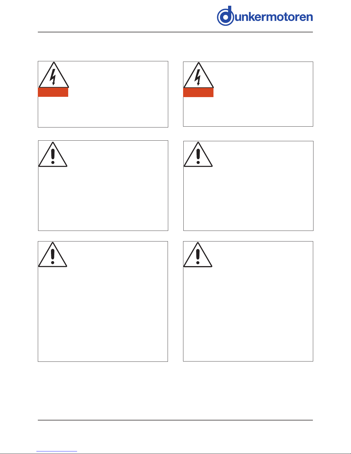
Herzschrittmacher: Mitarbeiter mit Herz-
schrittmachern dürfen nicht mit dem Gerät
arbeiten.
Achtung starke Magnete: Die Magnet-
stange enthält starke Magnete, die eisen-
haltige Objekte stark anziehen. Computer
Disks und Kreditkarten können Schaden
nehmen.
Achtung Lebensgefahr durch Strom-
schlag: Potentiell lebensgefährliche
Stromschläge können während der Inbe-
triebnahme und Wartung des Geräts auf-
treten. Wenn Sie dieses Zeichen sehen, dann prüfen
Sie stets ob das Gerät spannungsfrei und gegen verse-
hentliches Einschalten gesichert ist. Besondere Vor-
sicht gilt bei der Arbeit an oder in der Nähe von der
Stromversorgung.
Heiße Oberäche. Oberächentempera-
turen von bis zu 80 °C können während
der Inbetriebnahme und Wartung des Mo-
tors auftreten. Stellen Sie sicher, dass Pri-
märeinheit und Magnetstange stets herunter gekühlt
sind bevor Sie mit den Arbeiten am Gerät beginnen.
Quetschgefahr: Die Primäreinheit könnte
sich unvorhergesehen Bewegen. Prüfen
Sie stets, dass das Gerät spannungsfrei
ist bevor Sie beginnen daran zu arbeiten.
Gefahr! Befolgen Sie die Sicherheitshin-
weise.
Elektrische Schutzmaßnahmen
Das Gerät muss mit Hilfe des grün/gelben elektrischen
Erdungsleiters geerdet werden.
4.1 Warning Symbols and Meanings
In this User Manual warning symbols are used. These
are intended to alert you to the potential hazards to
personnel which are associated with the equipment
described, in all aspects of use, including handling,
installation, operation and maintenance.
Heart pacemakers: Personnel tted with
pacemakers must not handle or work on
this equipment.
Strong magnets: The thrust rod contains
powerful magnets and will strongly attract
ferrous objects. Damage can occur to
computer disks and credit cards.
Electric shock. Potentially lethal voltages
may be present during the commissioning
and servicing of this equipment. Isolate and
disconnect all sources of electrical supply
before working on the equipment. Particular care needs
to be taken when working on or around motor phase
connections.
Hot surface. Surface temperatures of up
to 80 °C can be present during the
commissioning and servicing of this
equipment. Allow the forcer and thrust rod
to cool before working on the equipment.
Crush hazard. The forcer may move
unexpectedly. Always isolate all sources of
electrical supply before working on the
equipment.
General hazard. Follow the advice given.
Electrical safety
This equipment must be earthed using the green/
yellow conductor.

9
Version 08.2017 www.dunkermotoren.com
4.1 Warning symbols and meanings
EMC precautions: This equipment is intended for
use in a light industrial environment. It is recommended
that the following precautions be observed during
installation:
• Keep all cable lengths to a minimum.
• Provide as much physical separation as possible
between power and signal cables. In particular,
avoid long, parallel runs of cables.
• Maintain screen continuity throughout the cable
run.
• Use 360 degree screen terminations where
possible. “Pig-tail” terminations are not
recommended.
It is the responsibility of the User to ensure compliance
with any local electrical and EMC regulations in force at
the time of installation.
4.1 Warnsymbole und Bedeutungen
EMC Sicherheitsvorkehrungen: Das Gerät ist für
eine Verwendung in einer Leichtindustrieumgebung
vorgesehen. Es wird empfohlen, dass die folgenden
Sicherheitsvorkehrungen während der Inbetriebnahme
befolgt werden:
• Halten sie alle Kabel auf möglichst minimalen Läng-
en
• Stellen Sie sicher, dass so viel räumlicher Abstand
wie möglich zwischen Leistung-und Signalkabeln
besteht.
• Sorgen Sie für einen durchgängigen Kabelschirm
über die gesamte Kabellänge.
• Legen Sie den Schirm, wenn möglich, über 360˚ auf.
„Kabelschwanz“ Abschlüsse werden nicht emp-
fohlen.
Der Benutzer ist verantwortlich zur Gewährleistung
der Übereinstimmung mit lokal bindenden Strom-und
EMV Bestimmungen, die zum Zeitpunkt der Installati-
on geltend sind.

10
www.dunkermotoren.de Version 08.2017
5.Technical Data
5.1 Electrical specication
5. Technische Daten
5.1 Motorspezikationen
Notes/Anmerkungen
(1) S=series forcer phases, P=parallel forcer phases/ S= Phasen der Primäreinheit in Serie, P= Phasen der Primäreinheit parallel, (2) Reduce continuous stall force to
89% at 40°C ambient/ Bei 40°C Dauer-Startkraft auf 89% reduzieren, (3) Based on a 27 mm stroke/ Bedingung: Bewegende Magnetstange mit 27 mm Hub Nutzlast,
(4) Based on triangular move over maximum stroke and no payload/ Bedingung: Bewegende Magnetstange mit Dreiecksbewegung über den maximalen Hub, (5)
Based on a moving forcer and no playload/ Bedingung: Bewegende Magnetstange und keine Nutzlast
FORCER TYPE/Primäreinheit 2504 2506 2508 2510 units/Einheiten
S (1) P (1) S (1) P (1) S (1) P (1) S (1) P (1)
Peak force @ 25oC ambient for 1 sec/Spitzen-
Schubkraft @ 25˚C Umgebung, Dauer: 1s 312 156 468 234 624 312 780 390 N
Peak current @ 25oC ambient for 1 sec/
Spitzenstrom @ 25˚C Umgebung, Dauer: 1s 20 20 20 20 20 20 20 20 Apk
With 25 x 25 x 2.5 cm heatsink plate/
Mit 25 x 25 x 2,5 cm Kühlkörperplatte
Continuous stall force @ 25oC ambient (2)/
Dauerkraft @ 25˚C Umgebung (2) 51.2 51.2 69.5 69.5 86.4 86.4 102.4 102.4 N
Continuous stall current @ 25oC ambient/
Dauerstrom @ 25˚C Umgebung
2.31 4.62 2.10 4.20 1.96 3.92 1.86 3.72 Arms
3.27 6.54 2.97 5.94 2.77 5.54 2.62 5.24 Apk
Without heatsink plate/Ohne Kühlkörperplatte
Continuous stall force @ 25oC ambient (2)/
Dauerkraft @ 25˚C Umgebung (2) 42.5 42.5 59.5 59.5 75.1 75.1 90.0 90.0
N
Continuous stall current @ 25oC ambient/
Dauerstrom @ 25˚C Umgebung
1.92 3.84 1.80 3.60 1.70 3.40 1.63 3.26 Arms
2.72 5.44 2.54 5.08 2.41 4.82 2.31 4.62 Apk
Force constant (sine commutation)/
Kraftkonstante (Sinuskommutierung)
22.1 11.0 33.1 16.5 44.1 22.0 55.2 27.6 N/Arms
15.6 7.8 23.4 11.7 31.2 15.6 39.0 19.5 N/Apk
Back EMF constant (phase to phase)/Gegen-
EMK Konstante (Phase-Phase) 18.0 9.0 27.0 13.5 36.0 18.0 45.0 22.5 Vpk/m/s
Fundamental forcer constant/Grundkonstante
Priäreinheit 6.47 6.47 7.92 7.92 9.13 9.13 10.24 10.24 N/√ W
Eddy current loss/Wirbelstromverlust 9.51 9.51 12.55 12.55 15.58 15.58 18.61 18.61 N/m/s
Resistance @ 25oC (phase to phase)/
Widerstand @ 25˚C (Phase-Phase) 6.02 1.50 9.02 2.25 12.03 3.01 15.04 3.76
Ohm
Resistance @ 100oC (phase to phase)/
Widerstand @ 100˚C (Phase-Phase) 7.75 1.94 11.63 2.91 15.51 3.88 19.39 4.85 Ohm
Inductance @ 1kHz (phase to phase)/
Induktivität @ 1kHz (Phase-Phase) 3.90 0.97 5.85 1.46 7.80 1.95 9.75 2.44 mH
Electrical time constant/Elektrische
Zeitkonstante 0.65 0.65 0.65 0.65 0.65 0.65 0.65 0.65 ms
Continuous working voltage/Dauer
Betriebsspannung 380 380 380 380 380 380 380 380
V d.c.
Pole pitch (one electrical cycle)/Polabstand (ein
elektr. Zyklus) 51.2 51.2 51.2 51.2 51.2 51.2 51.2 51.2
mm
STA Peak acceleration (3)/STA
Spitzenbeschleunigung (3) 394 197 483 241 542 271 586 293
m/s2
STA Maximum speed (4)/STA
Maximalgeschwindigkeit (4) 5.9 4.4 5.3 5.1 4.7 5.6 4.2 5.8 m/s
STB Peak acceleration (5)/STB
Spitzenbeschleunigung (5) 223 111 223 111 235 117 256 128 m/s2
STB Maximum speed (4)/
Maximalgeschwindigkeit (4) 8.7 7.3 6.5 7.2 5.4 7.6 4.6 7.0 m/s

11
Version 08.2017 www.dunkermotoren.com
5.2 STA FORCE /VELOCITY PROFILES 5.2 STA KRAFT/GESCHWINDIGKEITSPROFILE
(WITH AN OPERATING VOLTAGE OF 325 VD.C.) (MIT EINER BETRIEBSSPANNUNG VON 325 VD.C.)
S=series forcer phases S=Seriale Phasen der Primäreinheit
P=parallel forcer phases P=Parallele Phasen der Primäreinheit
STA2504S force/velocity
PEAK
CONTINUOUS
0
40
80
120
160
200
240
280
320
0 1 2 3 4 5 6
Velocity (m/s)
Force (N)
STA2504P force/velocity
PEAK
CONTINUOUS
0
40
80
120
160
0 1 2 3 4 5
Velocity (m/s)
Force (N)
STA2506S force/velocity
PEAK
CONTINUOUS
0
100
200
300
400
500
0 1 2 3 4 5 6
Velocity (m/s)
Force (N)
STA2506P force/velocity
PEAK
CONTINUOUS
0
50
100
150
200
250
0 1 2 3 4 5 6
Velocity (m/s)
Force (N)
STA2508S force/velocity
PEAK
CONTINUOUS
0
100
200
300
400
500
600
700
0 1 2 3 4 5
Velocity (m/s)
Force (N)
STA2508P force/velocity
PEAK
CONTINUOUS
0
50
100
150
200
250
300
350
0 1 2 3 4 5 6
Velocity (m/s)
Force (N)
STA2510S force/velocity
PEAK
CONTINUOUS
0
100
200
300
400
500
600
700
800
0 1 2 3 4 5
Velocity (m/s)
Force (N)
STA2510P force/velocity
PEAK
CONTINUOUS
0
100
200
300
400
0 1 2 3 4 5 6
Velocity (m/s)
Force (N)

12
www.dunkermotoren.de Version 08.2017
5.2 STB FORCE /VELOCITY PROFILES 5.2 STB KRAFT/GESCHWINDIGKEITSPROFILE
(WITH AN OPERATING VOLTAGE OF 325 VD.C.) (MIT EINER BETRIEBSSPANNUNG VON 325 VD.C.)
S=series forcer phases S=Seriale Phasen der Primäreinhei
P=parallel forcer phases P=Parallele Phasen der Primäreinheit
STB2504S force/velocity
PEAK
CONTINUOUS
0
40
80
120
160
200
240
280
320
0 1 2 3 4 5 6 7 8 9
Velocity (m/s)
Force (N)
STB2504P force/velocity
PEAK
CONTINUOUS
0
40
80
120
160
0 1 2 3 4 5 6 7 8
Velocity (m/s)
Force (N)
STB2506S force/velocity
PEAK
CONTINUOUS
0
100
200
300
400
500
0 1 2 3 4 5 6 7
Velocity (m/s)
Force (N)
STB2506P force/velocity
PEAK
CONTINUOUS
0
50
100
150
200
250
0 1 2 3 4 5 6 7 8
Velocity (m/s)
Force (N)
STB2508S force/velocity
PEAK
CONTINUOUS
0
100
200
300
400
500
600
700
0123456
Velocity (m/s)
Force (N)
STB2508P force/velocity
PEAK
CONTINUOUS
0
50
100
150
200
250
300
350
0 1 2 3 4 5 6 7 8
Velocity (m/s)
Force (N)
STB2510S force/velocity
PEAK
CONTINUOUS
0
100
200
300
400
500
600
700
800
0 1 2 3 4 5
Velocity (m/s)
Force (N)
STB2510P force/velocity
PEAK
CONTINUOUS
0
50
100
150
200
250
300
350
400
0 1 2 3 4 5 6 7 8
Velocity (m/s)
Force (N)

13
Version 08.2017 www.dunkermotoren.com
5.3 Thermal Specications/ Thermische Daten
FORCER TYPE/ PRIMÄREINHEIT 2504 2506 2508 2510 units/
Einheiten
Maximum phase temperature/ Max.
Phasentemperatur
100 100 100 100 oC
Thermal resistance Rthphase-housing/ Thermischer
Widerstand Rth Phase-Gehäuse
0.41 0.27 0.20 0.16 oC/W
With 25 x 25 x 2.5 cm heatsink plate/ Mit 25 x 25 x 2,5 cm Kühlkörperplatte
Power dissipation @ 25oC ambient/
Verlustleistung @25°C Umgebung
62.3 77.0 89.2 100.2 Watt
Thermal resistance Rthhousing-ambient Thermischer
Widerstand Rth Gehäuse-Umgebung
0.79 0.69 0.64 0.59 oC/W
Without heatsink plate/ Ohne Kühlkörperplatte
Power dissipation @ 25oC ambient/
Verlustleistung @25°C Umgebung
43.1 56.4 67.6 77.3 Watt
Thermal resistance Rthhousing-ambient / Thermischer
Widerstand Rth Gehäuse-Umgebung
1.33 1.06 0.91 0.81 oC/W
Thermal time constant/ Thermische
Zeitkonstante
1188 1276 1377 1486 s
5.4 Mechanical Specications/Mechanische Daten
FORCER TYPE/
PRIMÄREINHEIT STA
2504
STA
2506
STA
2508
STA
2510
STB
2504
STB
2506
STB
2508
STB
2510
units/
Einheiten
Maximum stroke/Max. Hub 309 309 309 309 1180 1129 1078 1027 mm
Forcer mass/Gewicht
Primäreinheit
1.25 1.70 2.25 2.65 1.15 1.60 2.15 2.55 kg
Thrust rod mass/metre /
Gewicht pro Meter
Magnetstange
3.5 3.5 3.5 3.5 3.5 3.5 3.5 3.5 kg/m

14
www.dunkermotoren.de Version 08.2017
5.5 Positionsgeber
Als Positionsrückmeldung gibt der Lagegeber analoge
Signale, Sinus und Cosinus Dierenzsignale aus. Un-
ten dargestellt ist das Verhältnis zwischen der Gegen-
EMK und der Sensorsignale der Primäreinheit für eine
Bewegungsrichtung (wie mit den Pfeilen dargestellt).
Zu beachten gilt, dass +SIN oder -SIN immer phasen-
gleich mit der U Phase ist. Für die dargestellte Bewe-
gung ist –SIN phasengleich mit Phase U. In Gegen-
richtung ist +SIN phasengleich mit Phase U.
5.5 Position Sensor
The position sensor outputs analogue, dierential sine
and cosine signals for providing position feedback.
Figure C.1 shows the relationships between forcer
phase back EMF and position sensor outputs for one
direction of motion (as shown by arrows in Figures C.1
and C.2). It should be noted that +SIN or -SIN is always
in phase with forcer phase U. For the motion shown,
-SIN is in phase with forcer phase U. For motion in the
opposing direction +SIN is in phase with forcer phase
U.
Figure C.1 - e relationships between forcer phase back EMF and position sensor outputs/Abbildung C.1- Das Verhältnis
zwischen der Gegenkonstanten EMF und den Sensorsignalen der Primäreinheit.
Figure C.2 - Arrows indicate direction of motion/Abbildung C.2-Die Pfeile geben die Bewegungsrichtung an.
Hinweis:
Sollte der eingesetzte Servoregler nur einen Enco-
dereingang mit 5V TTL Pegel verarbeiten können, so
kann ein zusätzlichen Schnittstellenwandler (SI10)
dazwischengeschalten werden.
Nähere Infos siehe Doku SI10.
Notice:
If the used servo controller can only handle digital 5V
TTL signals, you can join up in circuit an additional
interface converter (SI10).
For more information, see Documentation SI10.

15
Version 08.2017 www.dunkermotoren.com
Anmerkungen
(1) Hängt von Steuerung ab. (2) Hängt von Steuerung
ab. Bei gleichbleibenden Betriebsbedingungen. Eige-
nerwärmung der Primäreinheit führt zur Ausdehnung
in der Magnetstange während der Erwärmungspha-
se. Im Hochlastbetrieb (entspricht einer Temperatur
im Innern der Primähreinheit von 80°C) dehnt sich
eine 1 m lange Magnetstange um typ 250 µm aus.
(3) Max. Fehler über 1 Meter bei gleichbleibenden
Betriebsbedingungen.
5.6 PRIMAREIHEIT UBER TEMPERATUR-
SENSOR
Es wird dringend empfohlen, den
Übertemperatursensor immer am
Antriebsverstärker oder der Servosteuerung
anzuschließen, um die Primäreinheit vor
Schäden durch zu hohe Temperaturen zu schützen.
Drei PTCs (Thermistoren mit positivem
Temperaturkoezient), die in die Phasen der
Primäreinheit eingebettet sind dienen der Absicherung.
Sobald sich die Temperatur der Primäreinheit einem
Wert von 100°C annähert, erhöht sich der elektrische
Widerstand der PTCs deutlich. Diese
Widerstandsänderung kann schaltungsrechnisch im
Antriebsverstärker oder in der Servosteuerung erkannt
werden. Um die Primäreinheit schützen zu können,
kann die Ausgangsleistung entsprechend reduziert
oder komplett ausgeschaltet werden.
Notes
(1) Dependent on amplier. (2) Dependent on amplier.
Under constant operating conditions. Self-heating of
the thrust rod by the forcer will cause expansion in the
thrust rod during the initial warm up period. In high
duty applications (corresponding to an internal forcer
temperature of 80°C) a 1 metre thrust rod will expand
typically by 250 µm. (3) Maximum error over 1 metre.
5.6 FORCER OVER TEMPERATURE SENSOR
It is strongly recommended that the forcer
over-temperature sensor is connected to
the drive amplier or servo controller at all
times in order to reduce the risk of damage
to the forcer due to excessive temperatures.
Protection is provided by three, positive temperature
coecient (PTC) thermistors embedded in the forcer
phases. As the forcer phase temperature approaches
100°C, the PTC thermistors exhibit a sharp increase in
electrical resistance. This change in resistance can be
detected by circuitry within the drive amplier or servo
controller and used to reduce or disable the output of
the drive amplier in order to protect the forcer.
SPECIFICATION VALUE UNITS
Output signal period 51.2 mm
Signal amplitude (between +/- signal) 1 Vpk-pk
Output current ±10 mA
Supply voltage 5 ± 0.25 V d.c.
Supply current (output current =0) 15 ± 5 mA
Resolution (1) 12 micron (µ)
Position Repeatability (2) ±12 micron (µ)
Absolute Accuracy (3) ±350 micron (µ)
ANGABE WERT EINHEITEN
Ausgangssignal-Periode 51.2 mm
Signal Amplitude (zw. +/- Signal) 1 Vpk-pk
Ausgangsstrom ±10 mA
Versorgungsspannung 5 ± 0.25 V d.c.
Versorgungsspannung
(Ausgangsstrom =0) 15 ± 5 mA
Auösung (1) 12 micron (µ)
Wiederholgenauigkeit (2) ±12 micron (µ)
Absolute Genauigkeit (3) ±350 micron (µ)

16
www.dunkermotoren.de Version 08.2017
5.7 KABELTYP
Die STA / STB Reihe hat zwei getrennte Verbindungs-
kabel für Leistungsversorgung und den Lagegeber.
Die erhältlichen Standardkabel sind exibel, und für
Schleppkettenanwendungen geeignet.
5.7 CABLE
The STA / STB has two separate cables providing
connections for forcer power and position sensor. The
standard cables supplied are exible and intended for
continuous ex or drag chain applications.
SPECIFICATION Value Units
Resistance in the temperature range -20oC to
+70oC60 to 750 Ohms
Resistance at 85oC <=1650 Ohms
Resistance at 95oC >=3990 Ohms
Resistance at 105oC >=12000 Ohms
Response time for a 20oC to 100oC temperature
step to register a trip 3 s
Maximum continuous voltage 30 Vd.c.
SPECIFICATION / ANGABEN POWER/LEISTUNG SENSOR/GEBER
Overall diameter (nominal)/
Durchmesser gesamt (nomina;l)
8.0 mm 5.8 mm
Outer jacket material/Material
Außenmantel
PUR PUR
Number of conductors/Anzahl Leiter 4 4 x twiseted pair/ 4 x
verdrilltes Doppelkabel
Size of conductors/Leiterquerschnitt 1.5mm2(16 AWG) 0.14mm2(26 AWG)
Screened / Unscreened/Geschirmt/
Ungeschirmt
Screened/Geschirmt Screened/Geschirmt
Minimum bending radius-xed
routing/Kleinster Biegeradius-Feste
Leitungsführung
42 mm 42 mm
Operating temperature-xed
routing/Betriebstemperatur-Feste
Leitungsführung
-30 oC to/bis +80 oC -30 oC to/bis +80 oC
Operating temperature- exible routing/
Betriebstemperatur- Flexible Verlegung
-15 oC to/bis +80 oC -15 oC to/bis +80 oC
ANGABE Wert Einheiten
Widerstand im Temperaturbereich von 20oC to
+70oC60 to 750 Ohms
Widerstand bei 85oC 1650 Ohms
Widerstand bei 95oC <3990 Ohms
Widerstand bei 105oC <12000 Ohms
Auslösezeit nach der ein Temperatursprung von
20˚C auf 100˚C erkannt wird. 3 s
Max. Dauer-Versorgungsspannung 30 Vd.c.

17
Version 08.2017 www.dunkermotoren.com
1
TB1
23
TOP VIEW OF POD WITH LID REMOVED
5.8 Verbindungen
Die folgenden Verbindungen benden sich innerhalb
des Klemmkastens der Primäreinheit:
5.8 CONNECTIONS
Connections within the forcer termination box are as
follows:
TB1 FUNCTION/FUNKTION CONDUCTOR DESIGNATION/
ZUORDNUNG DER LEITUNGEN
1 Forcer phase U/Phase der Primäreinheit U Black 1/ Schwarz 1
2 Forcer phase V/Phase der Primäreinheit V Black 2/Schwarz 2
3 Forcer phase W/Phase der Primäreinheit W Black 3/Scwarz 3
Chassis Protective earth + both cable screens/
Erdkabel und beide Schirme
Green/Yellow, Grün/Gelb
Figure C.4- Power cable connection at TB1/Anschluss Leistungskabel bei TB1
PL1
SIDE VIEW OF POD WITH LID REMOVED
78
12
Figure C.5- Sensor cable connection at PL1 on the Sensor PCB/
Sensor Kabelverbindung bei PL1 auf der Sensor-Leiterplatte
PL1 SENSOR PCB FUNCTION/FUNKTION CONDUCTOR DESIGNATION/
LEITUNGSZUORDNUNG
1 +SIN Blue/Blau
2 -SIN Red/Rot
3 +COS White/Weiß
4 -COS Brown/Braun
5 +5Vd.c. Yellow/Gelb
6 0V Green/Grünen
7 +TH (Thermistor) Pink/Rosa
8 -TH (Thermistor) Grey/Grau

18
www.dunkermotoren.de Version 08.2017
6 Installation
6.1 UNPACKING
• Check packaging for signs of damage.
• Metal surfaces may be hot
or below 0oC following prolonged
storage.
• Remove packaging. Do not discard. In the event of
items requiring return, it is recommended that the
original packaging be used.
• Ensure that the delivery note correctly reects your
order and the items delivered.
• Check equipment for signs of damage. Never use
the equipment if it appears damaged in any way.
• Read the User Guide before installing and using
this equipment.
8.2 INSTALLATION
Intended operating environment: This
equipment is intended for use in an environment
within the following conditions:
Operating temperature 0 to +40 °C
Storage temperature -25 to +70 °C
Humidity (relative) 0 to 95% non-condensing
Altitude (above mean sea level) 1000 m
Overvoltage category II
Pollution degree 2
EMC light industrial
6 Installation
6.1 AUSPACKEN
• Kontrollieren Sie die Verpackung auf Schäden
• Bei längerer Lagerung können
Metaloberächen heiß sein oder
niedriger als 0˚C betragen.
• Entfernen Sie die Verpackung. Verpackung bitte
nicht wegwerfen. Falls es dazu kommt, dass Teile
zurückgegeben werden müssen, können nur
Orginalverpackungen akzeptiert werden.
• Stellen Sie sicher, dass die Lieferdaten korrekt sind
und mit Bestellung und Lieferung übereinstimmen.
• Kontrollieren Sie den Motor auf Schäden. Benutzen
Sie auf keinen Fall Material, das Schäden aufweist.
• Lesen Sie die Gebrauchsanweisung bevor Sie
Gebrauch von dem Gerät machen.
8.2 INSTALLATION
Betriebsumgebung: Das Gerät ist für den Betrieb
unter den folgenden Umweltbedingungen vorgesehen.
Betriebstemperatur 0 bis +40 °C
Lagertemperatur -25 bis +70 °C
Luftfeuchtigkeit (relativ) 0 bis 95% nicht-
kondensierend
Betriebshöhe über N.N. 1000 m
Überspannungskategorie II
Verschmutzungsgrad 2
EMV leicht industriell

19
Version 08.2017 www.dunkermotoren.com
6.3 Mechanische Installation-XTA
Abbildung 2.1. zeigt eine Zeichnung der Baureihe
XTA. Die Baureihe XTA besteht aus der Primäreinheit
mit einem integrierten Plymerlager und der Magnet-
stange. Das integrierte Lager fungiert als Führung
für die sich bewegende Magnetstange. Es dient nicht
dazu, Radiallasten abzufangen. Wenn hohe seitliche
Belastungen auftreten, ist es ratsam, dass ein ex-
ternes Lager verwendet wird.
Die Primäreinheit XTA kann auf zwei Arten befestigt
werden:
• In dem man die T-Nuten auf der Oberseite der
Primäreinheit verwendet.
• In dem man M6 Befestigungen (4 Stück ) am End-
ansch verwendet
WICHTIG
Wenn die Endansch-Befestigungsmethode ver-
wendet wird, müssen die Befestigungen und die
Montageplatte aus Nichteisenmetallen bestehen,
wie zum Beispiel Aluminium, Edelstahl oder Plas-
tik.
Details zu den Abmessungen beider Methoden sind in
Abbildung 2.1 dargestellt.
Die empfohlenen Anzugsmomente sind:
M6 Endansch: 9 Nm M5 T-Nuten: 7 Nm
(beide sind trockenlaufend i.e. ohne Gewindesicher-
ung)
Die Magnetstange hat optional Außen- bzw. In-
nengewinde an beiden Enden. Diese können mit einer
Reihe von Standardindustriekomponenten verbunden
werden. Die Magnetstange hat an jedem Ende einen
externen Sicherungsring, um die Magnetstange in-
nerhalb der Primäreinheit zu halten. Diese fungieren
jedoch nicht als „hard-stop“ um übermäßige Bewegun-
gen zu verhindern, vielmehr liegt es in der Verantwor-
tung des Verbrauchers die Magnetstangen daran zu
hindern von der Primäreinheit abgestoßen zu werden.
6.3 Mechanical Installation-STA
The outline drawing of the STA is shown in Figure 2.1.
It comprises the forcer with an integrated plastic sleeve
bearing and the thrust rod. The integrated bearing acts
as a guide for the moving thrust rod. It is not intended to
withstand side loading. If side loading is expected then
it is advised that an external bearing is tted.
The STA forcer can be mounted by two methods.
• Using the T -slots in the top of the forcer.
• Using M6 xings (4 o) on the end ange.
IMPORTANT
When using the end ange xing method, the
xings and mounting plate must be of a non-
ferrous material such as aluminum, stainless steel,
and plastic for example.
Dimensional details for both are given in Figure 2.1.
The recommended tightening torque for the xings are:
M6 end ange: 9 Nm M5 T-nut: 7 Nm
(both non lubricated i.e. no thread lock)
The thrust rod has optional male and female threaded
connections at each end. These are intended to
interface to a number of standard accessories. The
thrust rod has an external circlip at each end to restrain
the thrust rod within the forcer. These are not intended
as “hard stops” to prevent over-travel and it is the
responsibility of the User to prevent the thrust rod from
being ejected from the forcer.

20
www.dunkermotoren.de Version 08.2017
6.3 Mechanical Installation-STA 6.3 Mechanische Installation-STA
Figure 2.1 Abbildung 2.1
30.0
M4 x 8 DEEP
8 MTG HOLES
70.0
130.0
29.0
PITCH TYP
4.0 60.0
18.5
28.5 133
188.5
STA2504
68.0
25.0
54.0
=
32.5
=
=
32.5
=
34.0
27.0
31
25.3
4 MTG HOLES M6 x 7 DEEP
=
54.5
=
45.7
=
31.6
=
=
50.0
=
4.25
A
4 MTG HOLES
M4 x 8 DEEP
EITHER SIDE
30.0
60.04.0
66.0
177.0
29.0
PITCH TYP
M4 x 8 DEEP
8 MTG HOLES
18.5
28.5 133
239.5
ACTUATOR ENVELOPE
= (2 x STROKE) + 239.3
(See Note 1)
ACTUATOR ENVELOPE
= (2 x STROKE) + 290.3
(See Note 1)
ACTUATOR ENVELOPE
= (2 x
STROKE) + 341.3
(See Note 1)
STA2508
30.0
60.04.0
72.0
222.0
29.0
PITCH TYP
M4 x 8 DEEP
8 MTG HOLES
18.5
28.5 133
290.5
ACTUATOR ENVELOPE
= (2 x STROKE) + 392.3
(See Note 1)
STA2510
STA2506
30.0
60.04.0
72.0
273.0
29.0
PITCH TYP
M4 x 8 DEEP
8 MTG HOLES
18.5
28.5 133
341.5
ALL DIMENSIONS IN MM
NOTE 1. ACTUATOR IS DOUBLE ACTING
TOLERANCE
2mm
NOTE 2. FLATS AT EACH END ARE NOT
RECOMMENDED FOR ALIGNMENT PURPOSES
NOTE 3. TOLERANCE AROUND SWAGED AREA MAY VARY
SEE NOTE 2
10.9
5.9
11.0
6.2
DETAIL A
SCALE 2:1
T - SLOT DETAIL
33.5 17.5
( See Table Below )
OVERALL LENGTH
1.0
( See Table Below )
ACTIVE LENGTH
1.0
M8 x 16
MTG BOSS THREAD
0.2
18.0
A/F TYP
25.0 0.1
MTG HOLE
M8 x 12 DP
THRUST ROD
20.0
±0.1
10.0
12.0
±0.2
12.0
±0.2
10.0
20.0
±0.1
16.0
END COLLAR DETAIL
SCALE 1:1.5
0.3
A
A
SEE NOTE 3
0.3
A
This manual suits for next models
16
Table of contents
Other dunkermotoren Controllers manuals
Popular Controllers manuals by other brands

Humboldt
Humboldt H-3185SD operating instructions

Eaton
Eaton Diesel Plus 4A55737H01 O & M Manual

LinMot
LinMot E1100-CO Data Sheet & Installation Guide

Festo
Festo EduTrainer 571849 operating instructions

Datalogic
Datalogic Controller SC6000 Quick reference guide

National Instruments
National Instruments PCI-7342 user manual