Dupla MultiControl Manual

MultiControl
Directions for Use

Table of Contents
1. Introduction......................................................................4
1.1 Safety instructions .............................................................4
1.2 Installation ..................................................................4
1.3 Controller and power switching unit ...............................................5
1.4 Display......................................................................6
2. Basic Functions ...................................................................7
2.1 Safety shutdown during programming ..............................................7
2.2 Function monitoring of external equipment ..........................................7
2.3 Temperature sensor fault recognition ...............................................7
2.4 Self-calibration of temperature sensor ..............................................7
3. Programmable Functions ...........................................................7
3.1 Water temperature control ......................................................7
3.2 Cooling operation .............................................................7
3.3 Cooling device control ..........................................................7
3.4 Temperature alarm ............................................................8
3.5 Timing circuit options ..........................................................8
3.6 pH set point .................................................................8
3.7 pH alarm ....................................................................8
3.8 pH electrode calibration ........................................................8
3.9 Memory function calibration .....................................................8
3.10 Time .......................................................................8
4. Quick Start Guide to Programming ...................................................9
5. Programming Instructions .........................................................10
5.1 Water temperature control .....................................................10
5.2 Switching to cooling operation...................................................10
5.3 Cooling device control .........................................................10
5.4 Setting temperature alarm ......................................................11
5.5 Setting switching times ........................................................11
5.6 Programming pH set point .....................................................12
5.7 Setting pH alarm .............................................................12
5.8 Calibrating pH electrode........................................................12
5.9 Setting calibration memory......................................................13
5.10 Setting time .................................................................13
6. Factory Settings / Reset ...........................................................13
7. Source of Fault ..................................................................14
8. Technical Specifications ...........................................................15
9. EC Declaration of Conformity ......................................................15
2

1. Introduction
1.1 Safety instructions
All electronic components of the aquarium computer must only be operated in sound condition. If the feeder
is damaged please have this replaced by a technician or send us the equipment for repair. Continued operation
may cause a fatal electric shock. Ensure that the controller (1) and power unit (12) do not come into contact
with water.
It is good practice to disconnect all electrical equipment from the mains before placing your hands in the
aquarium.
Hint: It is recommended to use a separate or dedicated, safety-switch protected supply which disconnects the
mains from the aquarium equipment in the event of an electrical fault.
1.2 Installation
Controller
The controller (1) has a mounting recess or slot (2) on the back, which mates with the
mounting rail (3), and may therefore be mounted using the screw set, (4) to a wall or the
aquarium cabinet. The 2 metre cable from the Power Unit, provides sufficient length to
allow positioning of the controller outside the aquarium furniture, so that all values and
switch states can be readily viewed.
Power unit
The Power unit (12) should
be fixed onto the side of
the aquarium cabinet, to
minimise any chance of
water contact in the event
of a leakage from the
aquarium or filter etc.
Temperature Sensor
Position the temperature sensor (11) at a place in the aquarium where
there is a good water current. It should not be attached near heating.
Be sure to mount it securely so that it cannot come loose nor emerge
from the water - this could lead to inaccurate displayed values and over-
heating of the aquarium.
1
11
2
3
4
12
11
33

1.3 Controller and Power Unit
(1) Controller
(2) Mounting Slot
(3) Mounting Bar
(4) Screw Set
(5) Display Cover
(6) Display
(7) Keypad Cover
(8) “Menu” Key
(9) ▲Key
(10) ▼Key
(11) Temperature Sensor
(12) Power Unit
(13) Power Unit Interval Timer 1, 2, 3
(14) CO
2
Control Channel
(15) Water Temperature Channel
(16) Substrate Temperature / Cooling Channel
(17) LED
4
3
2
11
6
5
1
7
10
9
8
13
14
15
16
12
17
1
4

1.4 Display
= Animation effect, appears in association with display of the CO
2
symbol
= Symbol for CO
2
channel - control of a heating device magnetic valve / appears when program-
ming and displaying CO
2
channel values
= Symbol for heating channel - control of a heating device / appears when programming and
displaying water temperature values
= Symbol for substrate temperature channel or alternatively, cooling channel - control of a substrate heater or
a cooling device / appears when programming and displaying substrate temperature / cooling values
HEAT = heating / heating function - indicates the “horizontal waves” channel is operating with a second
heating device
COOL = cooling / heating function - indicates the “horizontal waves” channel is operating with a cooling device
= Symbol of the 1
st
time-controlled channel / appears when programming and displaying the values
of the 1
st
time-controlled channel
= Symbol of the 2
nd
time-controlled channel / appears when programming and displaying the values
of the 2
nd
time-controlled channel
= Symbol of the 3
rd
time-controlled channel / appears when programming and displaying the values
of the 3
rd
time-controlled channel
= Appears when programming and displaying the value of the pH alarm, temperature alarm or the
calibration memory function
On / Off = Displays the timer status when programming and in operation / displays the activation or deac-
tivation of the pH alarm, the temperature alarm or the calibration memory function
Mo-Su = Display of programmable circuit times / single days Mo-Su, Mo-Fr, Sa-Su / Display of week days in
English
Cal = Appears during calibration
Set = Appears when entering set point
°8= Shows the number of the switching time when programming
88:88 = Numeric display
E01 = Temperature sensor – cable defect (open circuit)
E02 = Temperature sensor – probe defect (short circuit)
° C = Appears when programming and displaying the temperature
= Appears when accessing the menu structure
pH = Appears when programming and displaying the pH value / appears in connection with "CAL"
when calibrating the pH electrode
CAL = Appears when programming and displaying the calibration memory function
55

2. Basic Functions
2.1 Safety shutdown during programming: When accessing the programming mode, the channels pH control
„CO
2
“(14), water temperature (15) and substrate temperature / cooling (16) are disabled for safety
purposes.
2.2 Function monitoring of external devices: The power unit is fitted with green LEDs (17). These indicate
the active control of external devices. The three channels for the interval timer can be switched on and off
eight times each, within 24 hours.
2.3 Malfunction and short-circuit recognition of temperature sensor: The temperature sensor (11)
features recognition of sensor malfunction (open or short-circuit), which is displayed with E01 or E02. For
safety, the heater channel ist switched „off“ in this event, so that the aquarium cannot overheat.
If the aquarium is not heated by a Dupla Therm cable heater but an immersion heater, it is recommended to
only use such heaters with integrated thermostat and safety shutdown.
2.4 Self-calibration temperature sensor: The temperature sensor is a precision measuring instrument with a
maximum tolerance of 1%. If replacement is required, calibration is not necessary.
3. Programmable Functions
3.1 Control of water temperature: Water temperature is controlled with +/- 0.1° C accuracy.
Contact-less switching of the water temperature channel is achieved by use of an electronic triac switch.
The substrate temperature channel can be set within the range of 15° to 35.9° C. The substrate temperature
channel is automatically preset 0.1° C higher.
Example: You have set the water temperature to 25.0° C. At a measured 25.0° C, the water temperature chan-
nel switches off, however substrate heating continues. If the substrate heating is sufficient to raise the water
temperature to 25.1° C, then the substrate heating channel also switches off.
Warmth in the substrate strengthens the plant roots, increases the biological activity of the substrate and
creates circulation within the substrate for improved transportation of oxygen and nutrients. The best possible
requirements for healthy plant growth are achieved.
Hint: Immersion heaters with an integrated thermostat should be set 3-4° C higher than the required tempera-
ture, so that electronic control via the MultiControl can operate correctly.
3.2 Cooling operation: An inverting function can be enabled to change the substrate heating channel to a
cooling channel for controlling an external cooling device during the Summer months.
3.3 Cooling device control: Via the water temperature channel, the immersion heater heats the water up
to the preset temperature. If the temperature then increases more than the preset difference, a cooling device
can be controlled via the substrate temperature channel. When the cooling option is selected, the differential
between heating and cooling can be set as required. The control accuracy is 0.1° C.
Example: If the water temperature is at 25° C in COOL operation and the differential to the substrate heating
is 3° C, the immersion heater is switched off at 25° C. If, due to higher summer temperatures, the aquarium
continues to heat up to 28.0° C due to the summer temperature, cooling is activated.
Hint: If it is decided to use the cooling mode of the Multicontrol, it is suggested to retain the significant bene-
fits of substrate heating (see 3.1), a heating cable is controlled instead by the water temperature channel.
6

An immersion heater may also be connected to this channel, depending on the power of the heating cable
(e.g. Therm Set vs Thermik Set), and therefore it’s capacity to provide sufficient warmth in the cooler months.
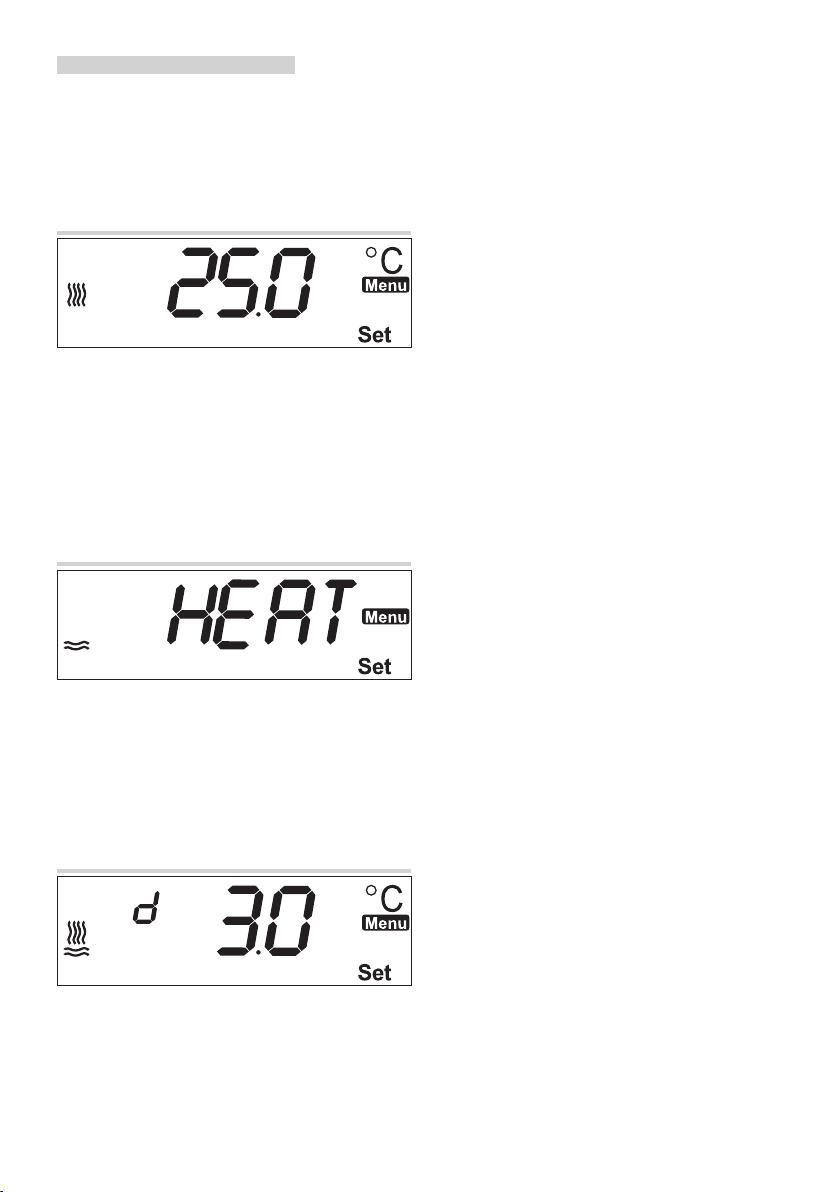
3.4 Temperature Alarm: When the water temperature falls below, or exceeds the programmed temperature
set-point, an audible and visual temperature alarm is activated. The alarm window can be preset between +/-
1° and 5° C. +/-3° C is set as the factory default. The alarm function can be switched on or off.
By default the function is set to “off”, to prevent the alarm operating on initial use when the sensor is not yet
positioned in the aquarium and the room temperature is too high or too low.
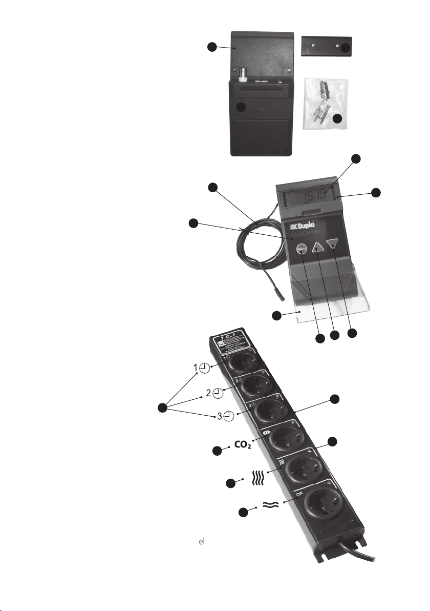
3.5 Circuit Times: Via 3 time-controlled channels, for example, day and night lighting, circulation pumps or
filters can be switched on and off, up to 8 times each, per day. External devices can be programmed daily,
Mo-Su, Mo-Fr, Sa-Su. The weekdays are abbreviated on the display. The capacity of the entire Power Unit is
1,500 W total. With individual channels having a maximum capacity of 1,000 W each.
3.6 pH Set Point: The pH set point can be adjusted within the limits of 4.0 - 9.9. Outside of these limits, the
pH channel is switched off. With the connection of a Dupla pH electrode, the pH level, may be continuously
monitored, and with a Dupla Magnetic Valve also connected to the Multicontrol, pH-controlled CO
2
fertilisation
may be utilised. Switch hystereris (the difference between the switching point and the triggering point) is 0.1
pH, and the control accuracy is +/- 0.1 (reference value). In order to ensure the accuracy of measurement and
therefore the control circuit, the MultiControl provides an optional six-week calibration memory function
CAUTION: If no pH electrode is connected to the MultiControl, so that the BNC socket is open, inevitably, ficti-
tious pH values will be displayed in individual as well as toggle mode (where the displayed values change from
one to the next in a 2 second cycle). To overcome this, by default, these values are hidden when a pH electrode
is not connected. If you want them to be displayed, please select “on” when programming the
pH point setting.
3.7 pH Alarm: When the programmed pH set-point is either not met or exceeded, there is an acustical and
optical pH alarm. The alarm window can be set between 0.5 and 4.0 pH deviation from the set point. By de-
fault, a deviation of pH 0.5 is preset. The alarm function can be enabled or disabled (switched “on” or “off”).
The beep can be silenced by pressing the ▲or ▼key.
3.8 Calibrate pH Electrode: The factory setting of the calibration points is pH 7 and pH 4, the calibration
sequence first is pH 7, then pH 4. The calibration process can be cancelled by pressing the ▲ and ▼ key
simultaneously.
3.9 Calibration Memory Function: With this feature enabled, every six-weeks “CAL” and “pH” flashes on
the display as a reminder to check the pH electrode calibration. In order to calibrate the pH electrode, enter
programming mode by pressing the “Menu” key and go to the menu item “CAL” and “pH”.
To disable of the calibration memory function, continue to scroll through the menu items and set the function
to “off”. If you prefer not to carry out a calibration at the moment, the memory display clears after activating
any key and reappears in another 6 weeks.
3.10 Time: The MultiControl has a built-in real-time clock. Changing from summer time to winter time must
be done manually.
77

4. Quick Start Guide to Programming
Switch display lighting ‘on’ or ‘off’: Press and hold the ▼ key = on/off.
Toggle mode: Temperature and time of day are displayed alternately
in a 2 second rhythm (factory preset).
Single mode: Optionally either pH value, temperature or time of day are displayed
continuously (by pressing the ▲and ▼key).
Hint: Shall the pH value be displayed in the toggle and single mode,
please select “on” when programming the pH set-point in
the menu item.
Changing from toggle to single mode: Press and hold the ▲ key.
Audible acknowledgment: Press key for a moment , i.e. a ‘tap’ = short sound
Hold key down, i.e. for 2 seconds = long sound.
Switching to programming mode: A) Pressing the “Menu“ key enters the main programming
menu. During programming the () symbol is displayed.
Moving within the menu structure: B) It is possible to scroll through the menu items with the ▲and
▼ keys (order: water temperature – substrate temperature differential
- cooling devices – temperature alarm – switching times – pH set
point – pH alarm – calibrate pH electrode – calibration memory - time)
Modifying programming: C) Quickly pressing “Menu“ enables the modification of programmed
values, the changeable value flashes.
D) Increase or decrease required values with the ▲ and ▼keys.
E) Acknowledge by activating the “Menu“ key.
For modification of other programmed values continue from step B).
Quitting the programming mode: F) Quitting the programming mode and accessing the operational
mode is done automatically after 3 minutes of inactivity or “Menu“
by holding down the key.
Enter programming menu
Scroll up or down in menu
Enable change in value
Increase or lower value
Acknowledge value change
Press & hold key, to quit programming
and access operating mode
8

5. Programming Instructions
First tap “Menu“ key to start the programming mode.
Hint: The symbol ”Menu” indicates you are in the programming mode. By holding down “Menu” it is possible
to quit the programming mode at any time.
5.1 Control of Water Temperature
When pressing the “Menu“ key, “25.0” flashes on the display.
Set the required value with the ▲or ▼key.
Acknowledge with “Menu” key, “0” will flash.
Set the required value with the ▲ or ▼key.
Acknowledge with the ”Menu“ key to return to the main menu.
Scroll through to the next menu item with the ▲key.
5.2 Switch to Cooling Operation
If the alternate cooling operation is not desired, scroll directly to the next menu item by pressing the ▲key.
Otherwise press the “Menu“ key -”HEAT“ flashes.
Change to “COOL“ with the ▲ key
Acknowledge with “Menu“ to return to the main menu.
Scroll through to the next menu item with the ▲ key.
5.3 Control of a Cooling Device
Press the “Menu” key, “3.0” flashes
Set the required value with the ▲ or ▼key.
Acknowledge with the “Menu“ key to return to the main menu.
Scroll through to the next menu item 10 with the ▲ key.
99

5.4 Setting Temperature Alarm
Press “Menu” key, “3.0” will flash.
Set the required value with the ▲or ▼key.
Acknowledge with “Menu”, “Off” will flash.
To activate the temperature alarm, set display to “On” with the ▲or ▼ key.
Acknowledge with ”Menu“ to return to the main menu.
Scroll to the next menu item with the ▲key.
5.5 Setting Switching Times
Press the “Menu” key, “1” flashes.
Press the “Menu” key to set the switch-on time of the slot, “00:” will flash.
Set the desired hour switching-on time with the ▲or ▼ key.
Acknowledge with “Menu” key, “:00” will flash.
Set the desired minutes switching-on time with the ▲or ▼ key.
Acknowledge with the “Menu” key, “Off” will flash.
Now set switching-off time of slot .
Set the desired hour switching-off time with the ▲or ▼ key.
Acknowledge with “Menu”, “:00” will flash.
Set the desired minutes switching-off time with the ▲or ▼ key.
Acknowledge with “Menu”, “Off” will flash.
Set the day or days with the ▲or ▼ key.
Acknowledge with “Menu”, “1” will flash.
If you want to set (up to 7) other switching on/off times of the slot , press ▲ and program in the same
way. In order to quit sublevels of switching times of , hold down „Menu“ to return to the main menu.
Scroll through to the next menu item 11 with ▲.
10

5.6 pH Program Set Point
Press the “Menu” key, “7.0” flashes.
Set the required value with the ▲or ▼ key.
Acknowledge with the “Menu” key, “Off” flashes.
With the ▲or ▼ key, set the display to “On” when a pH electrode is disconnected.
Acknowledge with the ”Menu“ key to return to the main menu.
Scroll to the next menu item with the ▲ key.
5.7 Setting pH Alarm
Press the “Menu” key, “0.5” flashes.
Set the required value with the ▲or ▼ key.
Acknowledge with “Menu” - “Off” flashes. Set to “On” if a pH electrode is connected.
Otherwise set to “Off” , to avoid a meaningless pH value being displayed in normal or toggle mode if no
electrode is connected and the pH BNC socket is open.
To activate the pH alarm, set the display to “On” with the ▲or ▼ key.
Acknowledge with the “Menu” key to return to the main menu.
Scroll through to the next menu item with the ▲key.
5.8 Calibrating pH Electrode
1. Connect the pH electrode to the MultiControl and remove the protective cap from electrode tip.
2. Rinse electrode tip briefly with Dupladest.
3. Press the “Menu” key - “7” appears at the top-left of the display.
4. Dip the electrode into the pH 7 solution. When the displayed measurement has settled, press and hold
the “Menu” key (until beep) to accept value; “4” appears at top-left of display.
5. Rinse electrode tip briefly with Dupladest.
6. Dip the electrodes into the pH 4 solution. When the displayed measurement settled, press and hold the
”Menu” key (until beep) to accept value; this will bring you back to the main menu.
7. Rinse electrode tip briefly with Dupladest.
8. Fix electrode in the aquarium with suction cups.
9. Scroll through to the next menu item with the ▲key.
The calibration can be interrupted at any time by pressing the ▲or ▼ key at the same time.
1111

5.9 Setting Calibration Memory
Press “Menu“ key, “On” display flashes.
Set key to “Off” with the ▲or ▼ key to turn off memory function.
Acknowledge with ”Menu“ to return to the main menu.
Scroll through to the next menu item with ▲key.
5.10 Setting Time
Press “Menu” key, “00:” flashes.
Set the current time in hours with the ▲or ▼ key.
Acknowledge with “Menu”, “:00” flashes.
Set the current time in minutes with the ▲or ▼ key.
Acknowledge with “Menu”, “Mo” flashes.
Set the current week day with the ▲or ▼ key.
Acknowledge with “Menu” to return to the main menu.
Scroll through to the next menu item with the ▲key.
To finish programming, hold ”Menu“ key down until display changes.
6. Factory Setting / Reset
Target temperature water heating: 25.0° C Target temperature substrate heating: 25.1° C
Difference heating / cooling differential: 3.0° C Temperature Alarm: 3° C (off)
Target pH control: 7 pH Alarm: 0.5 (off)
Calibration memory function: On Time switch position 1: Off
Time switch position 2: Off Time switch position 3: Off
Should your aquarium computer not be working correctly, please carry out a reset as follows:
1. Switch off power to MultiControl.
2. Turn power back on again while holding down the “Menu” key.
3. Release “Menu” key.
Caution: Activating the reset function will result in a loss of all programmed settings.
12

7. Source of Fault
In the case of a problem, first reset to the factory settings. If this does not solve the problem, please search for
the fault in the following table:
Fault Possible cause Solution
Temperature control is not
working
Immersion heater thermostat
overriding MultiControl
Set heater thermostat 3-4° C higher
than the MultiControl
Display E01 Temperature sensor cable break /
Temperature sensor not connected
Replace or connect temperature
sensor
Display E02 Temperature sensor hot-wired Replace temperature sensor
Alarm cannot be
deactivated
Temperature sensor defect Replace temperature sensor
External devices are not
operated at the preset time
Time setting inactive Check time setting and selection of
week-day
Fluctuating temperature
display
Temperature sensor cable too close
to a power cable
Re-locate temperature sensor
differently
pH value is not displayed Display was switched off Switch display on
pH value is not controlled pH control is not activated Activate pH control
Fluctuating pH value
pH electrode cable too close to a
power cable / the values displayed
during the calibration process had
not settled sufficiently.
Re-locate pH electrode cable / re-
calibrate pH electrode - if necessary,
2-3 times.
If repair is required, please return to where purchased.
1313

8. Technical Specifications
Operating voltage: 230 V / 50 Hz
Operating temperature: 0-60° C
Power Unit total load capacity: 1,500 W
Power Unit total fuse rating: 6.3 A/T
Data storage: power failure safe with E-Prom parameter memory
pH Control
pH control range: 4.0 - 9.9
Control accuracy: +/- 0.1 (reference value)
Alarm window: 0.5-4
Switching hysteresis: 0.1 pH
Connection power: 1,000 W
Calibration memory: Six-week
Water Temperature
Temperature control range: 15 – 35.9° C
Control accuracy: +/- 0.1 °C
Alarm window: 1.0 – 5.0° C
Switching: adjustable contact-less electronic triac
Switching hysteresis: 0.1° C
Connection power 1,000 W
Substrate Temperature / Cooling
Differential to water temperature: 1.0 – 5.0° C adjustable
Connection power: 1,000 W
Time-controlled slots
External equipment: user-defined
Connection power: 1,000 Wt
9. EC Declaration of Conformity
The manufacturer declares that the equipment meets the requirements of the applicable EHC standards and
therefore satisfies the provisions of the EC directives 89/336/EG.
Subject to technical modifications.
14

15
Dupla CO2Armatur Delta
Art. Nr. 80200
Dupla
CO2Armatur Alpha
Art. Nr. 80203
1
1
1
3
3
4
4
4
5
5
6
6
7
7
8
8
1
2
2
Dupla Magnetventil
Art. Nr. 80242
Dupla CO2Depot
500 g Art. Nr. 80220
1000 d Art. Nr. 80225
Dupla Thermik Set
20 W Art. Nr. 80680
40 W Art. Nr. 80681
60 W Art. Nr. 80682
Dupla Therm Set
100 W Art. Nr. 80685
150 W Art. Nr. 80686
200 W Art. Nr. 80687
250 W Art. Nr. 80688
Dupla Electra II
Dupla Turbomini
Art. Nr. 80360
Dupla CO2Reaktor 400
Art. Nr. 80185
Dupla CO2Reaktor S
Art. Nr. 80215
Dupla pH-Elektrodenset
Art. Nr. 80290
Connector plan of recommended
Dupla products

DOHSE AQUARISTIK KG
Otto-Hahn-Str. 9 • D-53501 Gelsdorf
Telefon: 0049-(0)22 25 - 94 15-0
Fax: 0049-(0)22 25 - 94 64 94
www.dohse-aquaristik.de
Other manuals for MultiControl
1
Table of contents
Other Dupla Aquarium manuals