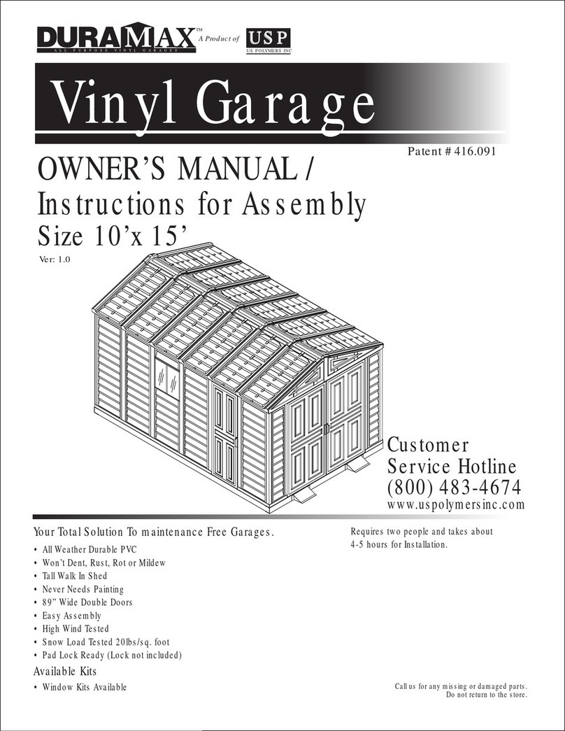
Dura-Max 10x15 Ft with Extension Kit User manual

A PRPE GARAGE
A roduct of
All Wether Durble C
Wont Dent Rust Rot or Mildew
Tll Wl In Shed
eer eeds intin
8” Wide Double Doors
Es Assembl
Hih Wind Tested
Snow Lod Tested 20lbs/s. oot
d Loc Red (Loc not included)
Cll us or n missin or dmed rts.
Do not return to the store.
Patent 416.091
M
F
Window its Ailble
1
HH
2
H
F
Instructions or Assembl
10F1F(Arox.)
Vinyl Garage
H
003
www.durmxb.com
Building imensions (ne Extension)
Approximate
ie torage Area
. Ft. Cu. Ft.
Exterior imension nterior imension
all to all
idth Inc
idth epth Height
10 2 12 26 34 160 3
31
123 3 31 72
Feet
inc inc inc
epth Inc Height Inc
125 3
Roof Edge to Edge
125 12 31 5 12
Base imension


Parts List
Cordless Drill - Philips Head
Hammer or Rubber mallet
Carpenters Square
8’ Step Ladder
Adjustable pliers
Level - 3ft.
Tape Measure
Caulk Gun
Waterproof Clear Silicon
Sealant
Hand Gloves
Tools You Will Need
ACCESSORIES
CODE
DESCRIPTION QTY
FDCL DOOR COLUMN FITTING LEFT 1
FDCLC DOOR COLUMN FITTING LEFT 1
FDCR DOOR COLUMN FITTING RIGHT 1
FDCRH DOOR COLUMN FITTING RIGHT 1
FCC CORNER COLUMN FITTING 4
FMC MIDDLE COLUMN FITTING 11
FCB CENTER BAND FITTING 4
RJ 90 DEGREE JOINT 4
PPG ROOF PLUG WITH WASHER 128
PIN ROOF PIN 128
EPS END PLUG SQUARE 7
CBC CENTER BAND COVER 3
TCH TOP CORNER 8
S1 DIA. 4.2 x 16mm. (5/32” x 5/8”)
SHEET METAL SCREW 420
S2 DIA. 4.2 x 32mm. (5/32” x 1 1/4”)
SHEET METAL SCREW 16
S7 DIA. 4.2 x 10mm. (5/32” x 3/8”)
SHEET METAL SCREW 40
S3 M4 x 10mm. (M5/32” x 3/8”)
MACHINE SCREW WITH NUT 33
S8 M8 x 25mm. (M5/16” x 1”)
HEX. BOLT & NUT WITH WASHER 9
CODE DESCRIPTION QTY
RS16L DOOR STOPPER LEFT 1
RS16R DOOR STOPPER RIGHT 1
RG RAMP 2
SP SIDE PANEL 15
FSPH FRONT SIDE PANEL 2
FPL FACIA PANEL LEFT 2
FPR FACIA PANEL RIGHT 2
RP ROOF PANEL 12
RRS RIDGE COVER 6
DL LEFT DOOR 1
DR RIGHT DOOR 1
DS DOOR SMALL 1
FOUNDATION
CODE DESCRIPTION QTY
F01H FOUNDATION ‘U’ CHANNEL 2
F02H FOUNDATION ‘U’ CHANNEL 2
F03 FOUNDATION ‘L’ ANGLE 4
F04A FOUNDATION ‘U’ CHANNEL 6
F05A FOUNDATION ‘U’ CHANNEL 6
F06A FOUNDATION ‘U’ CHANNEL 21
F07 FOUNDATION ‘U’ CHANNEL 18
F03H FOUNDATION ‘U’ CHANNEL 4
F08 FOUNDATION ‘U’ CHANNEL JOINT 8
S1 DIA. 4.2 x 16mm. (5/32” x 5/8”)
SHEET METAL SCREW 150
CODE DESCRIPTION QTY
B1LH FRONT ‘U’ CHANNEL LEFT 1
B1RH FRONT ‘U’ CHANNEL RIGHT 1
B1LA FRONT ‘U’ CHANNEL LEFT 1
B1RA FRONT ‘U’ CHANNEL RIGHT 1
B21 SIDE ‘U’ CHANNEL 1
B22 SIDE ‘U’ CHANNEL 1
B3LA BACK ‘U’ CHANNEL LEFT 1
B3RA BACK ‘U’ CHANNEL RIGHT 1
EXTL EXTENSION ‘U’ CHANNEL LEFT 3
EXTR EXTENSION ‘U’ CHANNEL RIGHT 3
CMA MIDDLE COLUMN 8
CMH MIDDLE COLUMN 3
CCA CORNER COLUMN 4
CDLA LEFT DOOR COLUMN 1
CDLH LEFT DOOR COLUMN 1
CDRA RIGHT DOOR COLUMN 1
CDRH RIGHT DOOR COLUMN 1
CB1A CB1 CENTER BAND 1
CB1H CB1 CENTER BAND 2
CB3A CB3 CENTER BAND 1
CB3XA CB3 CENTER BAND 5
CB4A CB4 CENTER BAND 1
CB4H CB4 CENTER BAND 2
CB6H CB6 CENTER BAND 1
RS1H RS1 ROOF STRUCTURE 4
RS2A RS2 ROOF STRUCTURE 4
RS3LA RS3 ROOF STRUCTURE LONG 5
RS3LH RS3 ROOF STRUCTURE LONG 1
RS4XA RS4 ROOF STRUCTURE 10
RS5A RS5 ROOF SRTUCTURE 4
RS6H RS6 ROOF STRUCTURE 8
RS7H RS7 ROOF STRUCTURE 8
RS13A RS13 ROOF STRUCTURE 8
RS8H RS8 ROOF STRUCTURE SUPP. LONG 4
RS9H RS9 ROOF STRUCTURE SUPP. SHORT 4
MJ MIDDLE JOINING SUPPORT 9
RS10A RS10 ROOF STRUCTURE SUPPORT 2
RS11A RS11 ROOF STRUCTURE SUPPORT SHORT 5
RS12A RS12 ROOF STRUCTURE SUPPORT LONG 3
RS14A SAGGING SUPPORT 24
DSHH DOOR STOPPER HORIZONTAL 1
RS19H VERTICAL SUPPORT - 1 4
RS20H VERTICAL SUPPORT - 2 4
RS15L RS15 ROOF STRUCTURE SUPPORT LEFT 2
RS15R RS15 ROOF STRUCTURE SUPPORT RIGHT 2
Note: Check all parts prior to installation.
MIDDLE COLUMNS
(CMA) (CMH)
U-Channels (B1LA, RA, LH,
RH)(B21) (B22) (B3LA) (B3RA)
ROOF STRUCTURE
(RS5A)(RS6H) (RS7H)
ROOF STRUCTURES (RS - 1H,
3LH, 3LA, 8H, 9H,19H,20H) (CB-
1A,1H, 2A, 3A, 4A,4H,6H) (MJ)
PVC 90 DEGREE JOINT
(RJ)
ROOF SUPPORT (RS2A)
(RS10A)
ROOF SUPPORT (RS4XA)
(RS11A) (RS12A)
MIDDLE COLUMN FITTING
(FMC)
CORNER COLUMN FITTING
(FCC)
LEFT DOOR COLUMN
(CDLA) (CDLH)
CORNER COLUMNS (CCA)
RIGHT DOOR COLUMN
(CDRA) (CDRH)
DOOR STOPPER
(DSHH)
CENTER BAND FITTING
(FCB)
DOOR COLUMN FITTING
(FDCL)
DOOR COLUMN FITTING
(FDCR)
DOOR COLUMN FITTING
(FDCLC)
DOOR COLUMN FITTING
(FDCRH)
ROOF PLUG WITH
WASHER (PPG)
ROOF PIN (PIN) END PLUG SQUARE (EPS)
SAGGING SUPPORT (RS14A) CENTER BAND COVER (CBC) TOP CORNER
(TCH)
MACHINE SCREW
(S3)
SHEET METAL SCREW
(S1), (S2), (S7)
FOUNDATION ‘L’ ANGLE
(F03)
FOUNDATION ‘U’ CHANNEL
(F01H,2H,3H,F04A,5A,6A,F07)
RAMP (RG)

Note: Check all parts prior to installation.
CODE DESCRIPTION QTY
EXTL EXTENSION ‘U’ CHANNEL LEFT 1
EXTR EXTENSION ‘U’ CHANNEL RIGHT 1
CMH MIDDLE COLUMN 2
CB2A CENTER BAND 2
RS3H RS3 ROOF STRUCTURE SHORT 2
MJ MIDDLE JOINING SUPPORT 4
RS4XA RS4 ROOF STRUCTURE 2
RS6H RS6 ROOF STRUCTURE 2
RS7H RS7 ROOF STRUCTURE 2
RS11A RS11 ROOF STRUCTURE SUPPORT SHORT 1
RS14A SAGGING SUPPORT 4
RS19H VERTICAL SUPPORT - 1 2
RS20H VERTICAL SUPPORT - 2 2
RS15L RS15 ROOF STRUCTURE SUPPORT LEFT 1
RS15R RS15 ROOF STRUCTURE SUPPORT RIGHT 1
SP SIDE PANEL 2
RP ROOF PANEL 2
RRS RIDGE COVER 1
One Extension Parts List
MIDDLE COLUMNS (CMH)
ROOF STRUCTURE
(RS6A) (RS7A) (RS13A)
ROOF PIN (PIN)
ROOF SUPPORT
(RS4XA) (RS11A)
ROOF STRUCTURES
(RS3H), (CB2A), (RS19H),
(RS20H), (MJ)
U-Channels (EXTL) (EXTR)
SAGGING SUPPORT (RS14A)
MIDDLE COLUMN FITTING
(FMC)
ACCESSORIES
CODE
DESCRIPTION QTY
FMC MIDDLE COLUMN FITTING 2
PPG ROOF PLUG WITH WASHER 58
PIN ROOF PIN 58
CBC CENTER BAND COVER 2
TCH TOP CORNER 4
S1 DIA. 4.2 x 16mm. (5/32” x 5/8”)
SHEET METAL SCREW 70
S2 DIA. 4.2 x 32mm. (5/32” x 1 1/4”)
SHEET METAL SCREW 4
S7 DIA. 4.2 x 10mm. (5/32” x 3/8”)
SHEET METAL SCREW 8
S8 M8 x 25mm. (M5/16” x 1”)
HEX. BOLT & NUT WITH WASHER 3
ROOF PLUG WITH WASHER
(PPG)
SHEET METAL SCREW
(S1), (S2), (S7)
FOUNDATION
CODE DESCRIPTION QTY
F06A FOUNDATION ‘U’ CHANNEL 3
F07 FOUNDATION ‘U’ CHANNEL 6
F03H FOUNDATION ‘U’ CHANNEL 2
F08 FOUNDATION ‘U’ CHANNEL JOINT 4
S1 DIA. 4.2 x 16mm. (5/32” x 5/8”)
SHEET METAL SCREW 26
FOUNDATION ‘U’ CHANNEL
(FO6A), (F07), (F03H)

Exploded View
FPL
FPR
RS1H
FPL
FPR
RS3LH
RS3LA
MJ
RS16R
RS3LA
RS3LA
RS2A
MJ
SP
SP
SP
SP
SP
SP
SP
SP
SP
SP
SP
SP
SP
SP
FSPH
FSPH
CDLA
CCA
CCA
CCA
CCA
CMA
CMA
CMA
CMA
CMA
CMA
CMA
CMA
CMH
CMH
CMH
CDRA
CDLH
CDRH
CB4H
CB4H
CB3XA
CB3XA
CB3A
CB4A
CB1A
CB6H
CB3XA
MJ
MJ MJ
CB3XA
CB3XA
B1LH
B1RH
B1RA
B1LA
EXTL
B22
B21
EXTR
B3LA
B3RA
F01H
F02H
F04A
F05A
F07
F07
F07 F02H
F01H
F04A
F05A
F07
F07
F07
SP
RS1H
RS4XA
RS4XA
RS4XA
RS2A
MJ
RS6H
RS7H
RS5A
RS1H
RS16L
DL
DR
DS
RS3LA
CB1H
CB1H
RG
RP
RP
RP
RP
RRS
RRS
RP
RP
RP
RP
MJ
RS2A
RS1H
RS4XA
RS3LA
RRS
RRS
RRS
RP
RP
RP
RP
RRS
SP
RS2A
RS4XA
RS4XA
RS15R
RS15R
RS15L

RS6H
RS7H
RRS
RP
RP
RS3H
RS3H
RS4XA
SP
SP
CMH
CMH
MJ
MJ
CB2A
CB2A
MJ
EXTL
EXTR
F07
F07
FO6A
Exploded View with One Extension

Roof Structure Exploded View

MJ
MJ
RS15L
RS15R
RS19H
RS20H
RS7H
RS7H
RS6H
RS6H
RS4XA
RS4XA
RS3H
RS3H
RS11A
Roof Structure Exploded View With One Extension

A. Foundation
Note: It is important that these instructions
are followed step by step.
1
1. Assemble the channel (F01H) & (F02H) together
using 4 (S1) screws. Make 2 sets.
F01H
S1 F02H
Parts Needed:
(2) Foundation ‘U’ Channel (F01H)
(2) Foundation ‘U’ Channel (F02H)
(4) Foundation ‘L’ Angle (F03)
(6) Foundation ‘U’ Channel (F04A)
(6) Foundation ‘U’ Channel (F05A)
(21) Foundation ‘U’ Channel (F06A)
(18) Foundation ‘U’ Channel (F07)
(4) Foundation ‘U’ Channel (F03H)
(8) Foundation ‘U’ Channel Joint (F08)
(1) Base ‘U’ Channel (B1LH)
(1) Base ‘U’ Channel (B1RH)
(1) Base ‘U’ Channel (B1LA)
(1) Base ‘U’ Channel (B1RA)
(1) Base ‘U’ Channel (B21)
(1) Base ‘U’ Channel (B22)
(1) Base ‘U’ Channel (B3LA)
(1) Base ‘U’ Channel (B3RA)
(3) Base ‘U’ Channel (EXTL)
(3) Base ‘U’ Channel (EXTR)
Screws (S1)
1. All parts are clearly marked and care
should be taken to use the correct one.
Note
Over lapping
Parts Needed For Each Extension:
(3) Foundation ‘U’ Channel (F06A)
(6) Foundation ‘U’ Channel (F07)
(2) Foundation ‘U’ Channel (F03H)
(4) Foundation ‘U’ Channel Joint (F08)
(1) Base ‘U’ Channel (EXTL)
(1) Base ‘U’ Channel (EXTR)
Screws (S1)
PART 1 : Assembling Shed With Extension Kit
2. Set the Torque limit of your Screw drill to
#3 or #4 to ensure the screws do not
strip the metal reinforcements.

2
2. Assemble the channel (F04A), (F05A) & (F07)
together using (S1) screws. Make 6 sets.
Add one (F07) for each Extension.
Make sure while assembling, the
channel position should be as
shown.
Note
3. Make a frame with the sub assemblies as shown
below.
Channel Position
Front
F01H
F02H F04A
F05A
F07
F07
F07
F01H
F02H
F04A
F05A
F07
F07
F07
S1
F04A
F05A
F07
F07
S1
F07
F07
F07
F07

4. Fix the ‘L’ angle (F03) to the channel at all the
four corners to make a perfect frame. See fig.
S1
F03
3
Make sure while assembling, the
channel position should be as
shown.
Note
5. Fix the channel (F04A), (F05A) & (F07) sub
assembly into the main frame as shown. See fig.
Front
F04A
F05A
F07
S1
6. Fix the channel (F06A) into the frame with
(S1) screws as shown. See fig.
Add 3 (F06A) for each Extension.
F07
F07
Channel Position
F06A
F07
F04A
F05A
F07
F07
F07
F07
F04A
F05A
F07
F07
F07
F07
F04A
F05A
F07
F07
F07
F07
F07
S1
Channel Position

. Assemble te ase U-Cannel on to of te
fondation it (1) scres as son in fi.
Add one (ET) (ETR) for each Extension.
Front
F01H
F02H
1H
1H
22
21
1
1
7. Place te cannel (F03H) into te frame ealy
saced as son. Use (F0) late to connect te
U cannel and te frame it (1) scres.
Add two (F03H) for each Extension.
1
F0
F03H
1
F0
F03H
3
3

5
b. Place te eterior rade CD 34 19mm.
lyood on to of te fondation. Plyood not
inclded.
ote
9. Place te ram (RG) to te front side of te
fondation and ee te distance accordin to te
eel distance. Use dia. 2.5mm. drill bit to transfer
te ole from (RG) and fi it (1) scres.
PT - 1.
Grael Floor with Plywood
a. After comletin te assembly of te base
U-cannel fill te ravel to te fondation to
srface only.
Fill the concrete inside the ramp also.
Concrete
Grael
Ramp
1
1220mm.
165mm. 223mm.
765mm. 627mm.
1220mm.
63mm.

B. alls Columns
Parts eeded
1 Door Colmn (CRA)
1 Door Colmn (CA)
1 Door Colmn (CRH)
1 Door Colmn (CH)
Middle Colmn (CA)
3 Middle Colmn (CH)
4 Corner Colmn (CCA)
15 Side Panel (P
)
2 ront Side Panel (FPH
)
2 C1 Center and (CB1H)
1 C1 Center and (CB1A)
1 C3 Center and (CB3A)
5 C3 Center and (CB3A)
2 C4 Center and (CBH)
1 C4 Center and (CBA)
1 C6 Center and (CBH)
3 Middle oinin Sort ()
2 Ram (RG)
4 Center and ittin (FCB)
3 Center and Cover (CBC)
7 nd Pl Sare (EP)
Scres (1)
Scres (2)
Macine Scres (3)
c. Secre te lyood to te fondation it
scres. Scres not inclded.
PT - 2.
Cement Floor with out Plywood.
After comletin te assembly of te base U-cannel
fill te concrete to te fondation to srface only.
Fill the concrete inside the ramp also.
Parts eeded For Each Extension
2 Middle Colmn (CH)
2 Side Panel (P
)
2 Center and (CB2A)
2 Middle oinin Sort ()
Ramp
Concrete
Concrete

1. Slide te door colmn (CRA) into te base
U-cannel (B1RH) on te rit side of te door.
ine te re drilled oles on colmn (CRA)
it base U cannel. Secre it to (1)
scres from inside. See fi.
Front
1H
1
23
1 Fig.3
1H
Always place panels into frame at an
angle on top and slide in sideways and
downward for easy insertion.
ote
Make sure panels are right side up with
panel shingles facing down. Check the
stamped label on top of all panels.
FSPH
2. Insert te front side anel (FPH ) into te
roove of colmn (CRA). Start at te bottom
of te anel at an anle ten s into lace.
ote FH
1H
FH
1
Fig.1
Fig.1
Fig.2
1H

8
3. Slide te corner colmn (CCA) into side anel
(FPH ) sin te colmn to te side anel.
Fig.1
Fig.2
Fig.3
FH
FH
1H
22
FH
1
1
23
4. i te center band fittin (FCB) to te colmn
(CCA) it (2) scre. eave it loose.
2
F

1
F
5. i te center band (CB1H) to te center band
fittin (FCB) it (1) scres. See fi.1. i te
oter end to te door colmn (CRA). See fi.2.
1H
1H
1
1H
1
2
Fig.1 Fig.2
6. i te center band (CBH) to te base U
cannel (B1RH) and door colmn (CRA) it
(1) scres. See fi.12. i te (EP) at te
end of (CB1H) (CBH). See fi.3.
1
H
H
1H
H
Fig.1 Fig.2
Fig.3
23
H
1H

7. orin from inside contine connectin te
7 side anels (P ) and colmns to te base U
cannel. Use (1) scres to fi colmn to base.
Add one side panel (P ) column (CH) for
each Extension.
H
H
1
. Slide te corner colmn (CCA) into side anel
(P ) sin te colmn to te side anel.
orin from otside se (1) scres to secre
colmn to base (ETR) (B3RA).
1
23
3
3
Fig.3
3
1
Fig.1 Fig.2
ote
H

Back
9. i te center band fittin (FCB) to te colmn
(CCA) it (2) scre. eave it loose.
2
F
10. Assemble te center bands (CB3A) it
middle oinin sort () it (1) Scres.
See fi.1. Assemble (CB3A) (CB3A)
toeter it (3) bolt nt. See fi. 2.
Assemble (CB3A) (CB2A) toeter it (1)
scres. See fi. 3.
Add one (CB2A) for each Extension.
1
2
3
3
3
3
1
Fig.1 Fig.2
3
3
1
3
3
3
2
3
Fig.3
3
2
1

11. Stabilie te side anels it center bands
(CB3A) (CB3A) assembly. See fi.1 to 6 and
follo te stes.
Fig.1 Fig.2
3
F
1
Fig.3 Fig.
H
1
2
1
1
F
Fig.5 Fig.
3 1H
1
H
H
H
3
3
3
15
2
2
3
2
2
12. orin from inside contine connectin te
3 side anels (P ) and colmns to te base U
cannel. Use (1) scres to fi colmn to base.
3
3
1
2
H
3
Table of contents
Other Dura-Max Tent manuals
Popular Tent manuals by other brands

Mountain
Mountain HardWear owner's manual

Forever Redwood
Forever Redwood ILLUMINATI PORCH PAVILION Assembly instructions

Dometic
Dometic TRT140 AIR Installation and operating manual

Coleman
Coleman Fossil Creek 9'x7' installation instructions

Trigano
Trigano DIABLO 6 Erection Instructions

llaza
llaza BIP-SCREEN 300 Technical manual

PLAYTIVE
PLAYTIVE 391882 2107 Instructions for use

Backyard Discovery
Backyard Discovery 14x10 BROCKTON PERGOLA Owner's manual & assembly instructions

CasualWay
CasualWay 2434589 instruction manual

Vaude
Vaude FERRET XT 3P user manual

DARCHE
DARCHE AIR-VOLUTION AT-4 instructions

Trustmade
Trustmade SCOUT installation manual