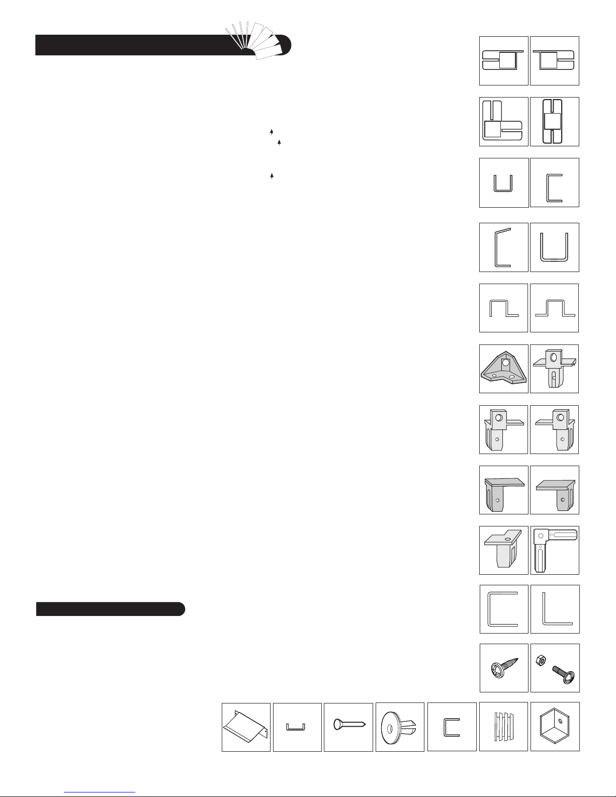
Parts List
Cordless Drill - Philips Head
Hammer or Rubber mallet
Carpenters Square
8’ Step Ladder
Adjustable pliers
Level - 3ft.
Tape Measure
Caulk Gun
Waterproof Clear Silicon
Sealant
Hand Gloves
Tools You Will Need
ACCESSORIES
CODE DESCRIPTION QTY
FDCL DOOR COLUMN FITTING LEFT 1
FDCLC DOOR COLUMN FITTING LEFT 1
FDCR DOOR COLUMN FITTING RIGHT 1
FDCRH DOOR COLUMN FITTING RIGHT 1
FCC CORNER COLUMN FITTING 4
FMC MIDDLE COLUMN FITTING 11
FCB CENTER BAND FITTING 4
RJ 90 DEGREE JOINT 4
PPG ROOF PLUG WITH WASHER 128
PIN ROOF PIN 128
EPS END PLUG SQUARE 7
CBC CENTER BAND COVER 3
TCH TOP CORNER 8
S1 DIA. 4.2 x 16mm. (5/32” x 5/8”)
SHEET METAL SCREW 420
S2 DIA. 4.2 x 32mm. (5/32” x 1 1/4”)
SHEET METAL SCREW 16
S7 DIA. 4.2 x 10mm. (5/32” x 3/8”)
SHEET METAL SCREW 40
S3 M4 x 10mm. (M5/32” x 3/8”)
MACHINE SCREW WITH NUT 33
S8 M6 x 20mm. (M1/4” x 3/4”)
HEX. BOLT & NUT WITH WASHER 9
CODE DESCRIPTION QTY
RS16L DOOR STOPPER LEFT 1
RS16R DOOR STOPPER RIGHT 1
RG RAMP 2
SP SIDE PANEL 15
FSPH FRONT SIDE PANEL 2
FPL FACIA PANEL LEFT 2
FPR FACIA PANEL RIGHT 2
RP ROOF PANEL 12
RRS RIDGE COVER 6
DL LEFT DOOR 1
DR RIGHT DOOR 1
DS DOOR SMALL 1
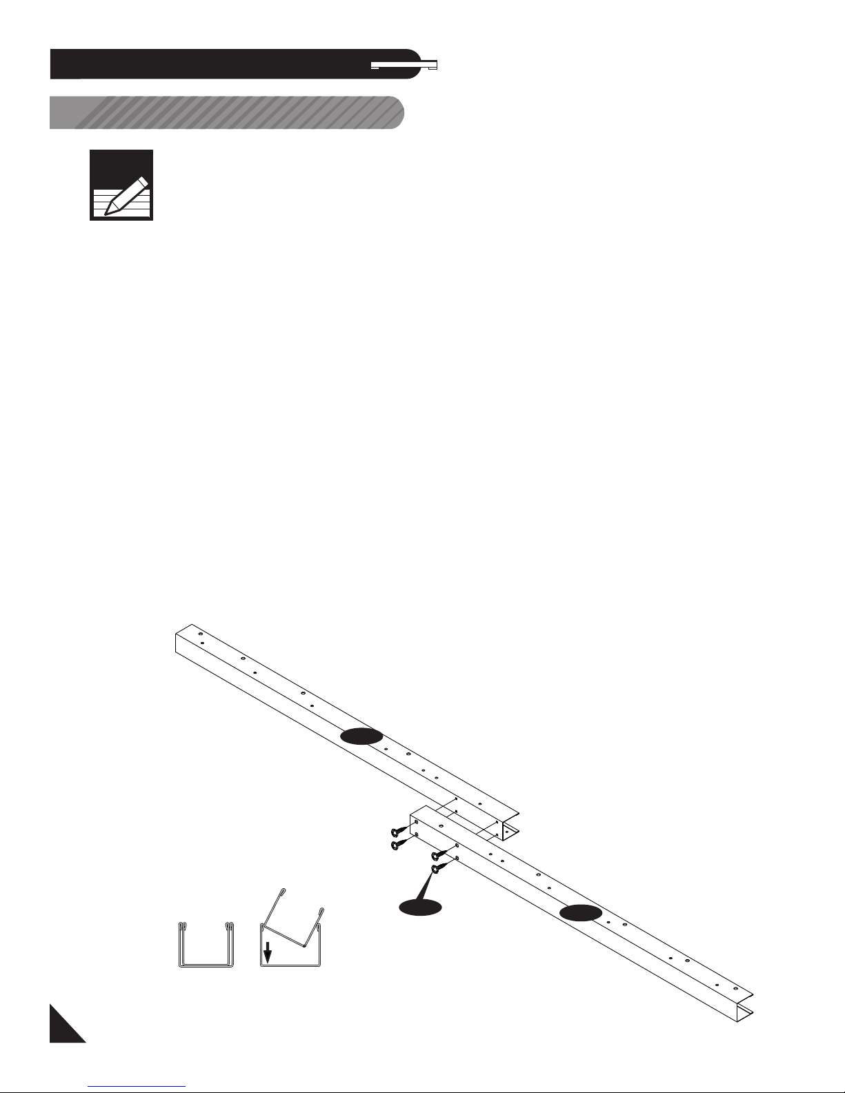
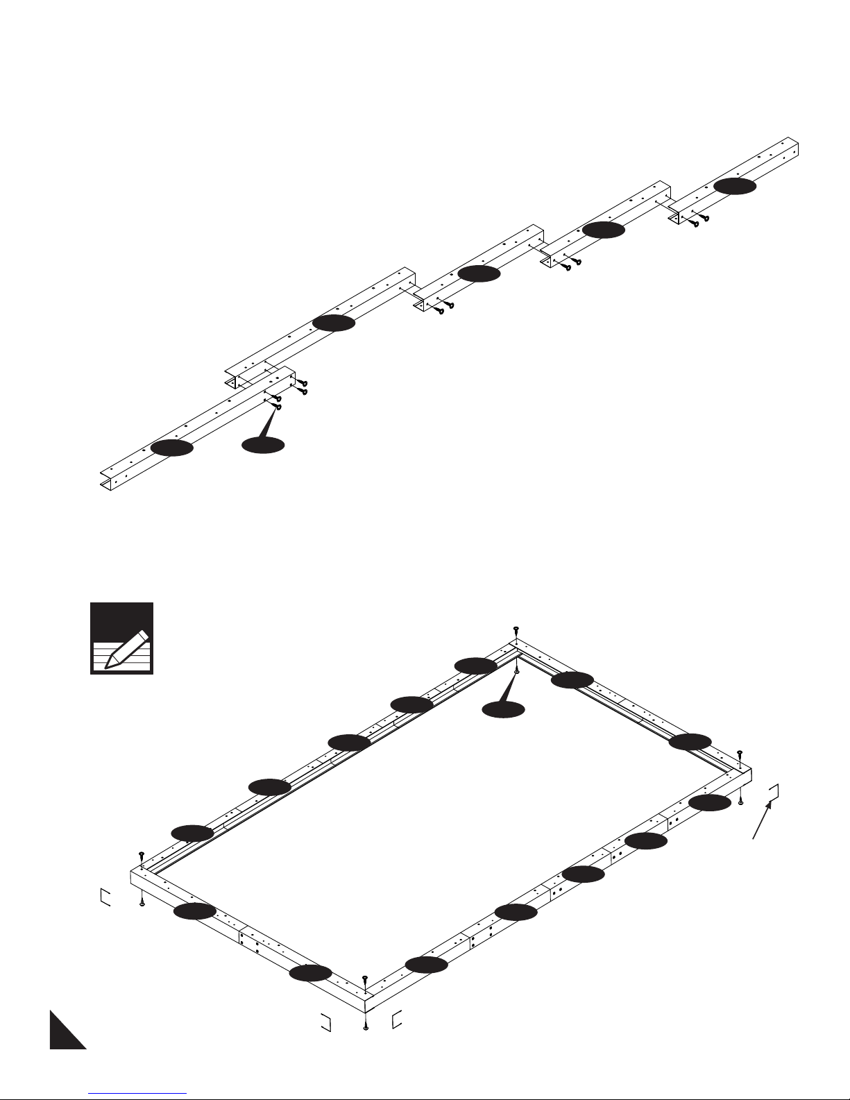
FOUNDATION
CODE DESCRIPTION QTY
F01H FOUNDATION ‘U’ CHANNEL 2
F02H FOUNDATION ‘U’ CHANNEL 2
F03 FOUNDATION ‘L’ ANGLE 4
F04A FOUNDATION ‘U’ CHANNEL 6
F05A FOUNDATION ‘U’ CHANNEL 6
F06A FOUNDATION ‘U’ CHANNEL 21
F07 FOUNDATION ‘U’ CHANNEL 18
F03H FOUNDATION ‘U’ CHANNEL 4
F08 FOUNDATION ‘U’ CHANNEL JOINT 8
S1 DIA. 4.2 x 16mm. (5/32” x 5/8”)
SHEET METAL SCREW 150
CODE DESCRIPTION QTY
B1LH FRONT ‘U’ CHANNEL LEFT 1
B1RH FRONT ‘U’ CHANNEL RIGHT 1
B1LA FRONT ‘U’ CHANNEL LEFT 1
B1RA FRONT ‘U’ CHANNEL RIGHT 1
B21 SIDE ‘U’ CHANNEL 1
B22 SIDE ‘U’ CHANNEL 1
B3LA BACK ‘U’ CHANNEL LEFT 1
B3RA BACK ‘U’ CHANNEL RIGHT 1
EXTL EXTENSION ‘U’ CHANNEL LEFT 3
EXTR EXTENSION ‘U’ CHANNEL RIGHT 3
CMA MIDDLE COLUMN 8
CMH MIDDLE COLUMN 3
CCA CORNER COLUMN 4
CDLA LEFT DOOR COLUMN 1
CDLH LEFT DOOR COLUMN 1
CDRA RIGHT DOOR COLUMN 1
CDRH RIGHT DOOR COLUMN 1
CB1A CB1 CENTER BAND 1
CB1H CB1 CENTER BAND 2
CB3A CB3 CENTER BAND 1
CB3XA CB3 CENTER BAND 5
CB4A CB4 CENTER BAND 1
CB4H CB4 CENTER BAND 2
CB6H CB6 CENTER BAND 1
RS1H RS1 ROOF STRUCTURE 4
RS2A RS2 ROOF STRUCTURE 4
RS3LA RS3 ROOF STRUCTURE LONG 5
RS3LH RS3 ROOF STRUCTURE LONG 1
RS4XA RS4 ROOF STRUCTURE 10
RS5A RS5 ROOF SRTUCTURE 4
RS6H RS6 ROOF STRUCTURE 8
RS7H RS7 ROOF STRUCTURE 8
RS13A RS13 ROOF STRUCTURE 8
RS8H RS8 ROOF STRUCTURE SUPP. LONG 4
RS9H RS9 ROOF STRUCTURE SUPP. SHORT 4
MJ MIDDLE JOINING SUPPORT 9
RS10A RS10 ROOF STRUCTURE SUPPORT 2
RS11A RS11 ROOF STRUCTURE SUPPORT SHORT 5
RS12A RS12 ROOF STRUCTURE SUPPORT LONG 3
RS14A SAGGING SUPPORT 24
DSHH DOOR STOPPER HORIZONTAL 1
RS19H VERTICAL SUPPORT - 1 4
RS20H VERTICAL SUPPORT - 2 4
RS15L RS15 ROOF STRUCTURE SUPPORT LEFT 2
RS15R RS15 ROOF STRUCTURE SUPPORT RIGHT 2
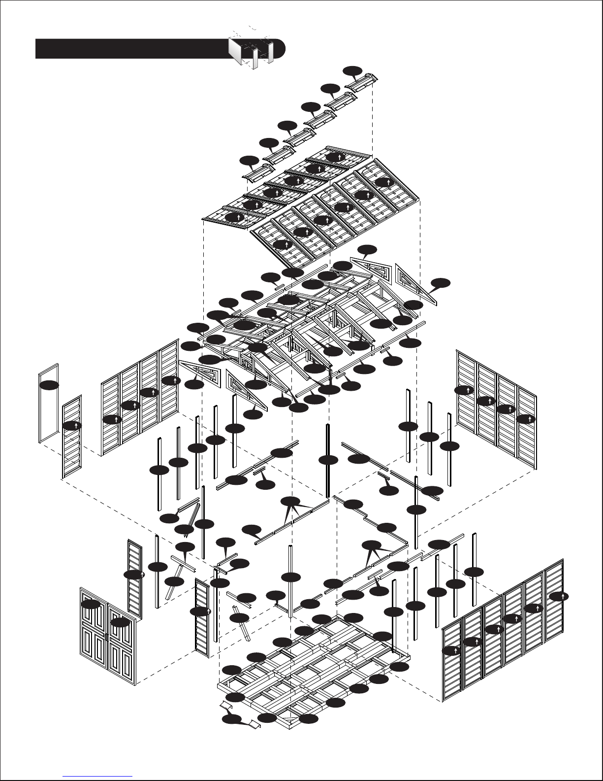
Note: Check all parts prior to installation.
MIDDLE COLUMNS
(CMA) (CMH)
U-Channels (B1LA, RA, LH,
RH)(B21) (B22) (B3LA) (B3RA)
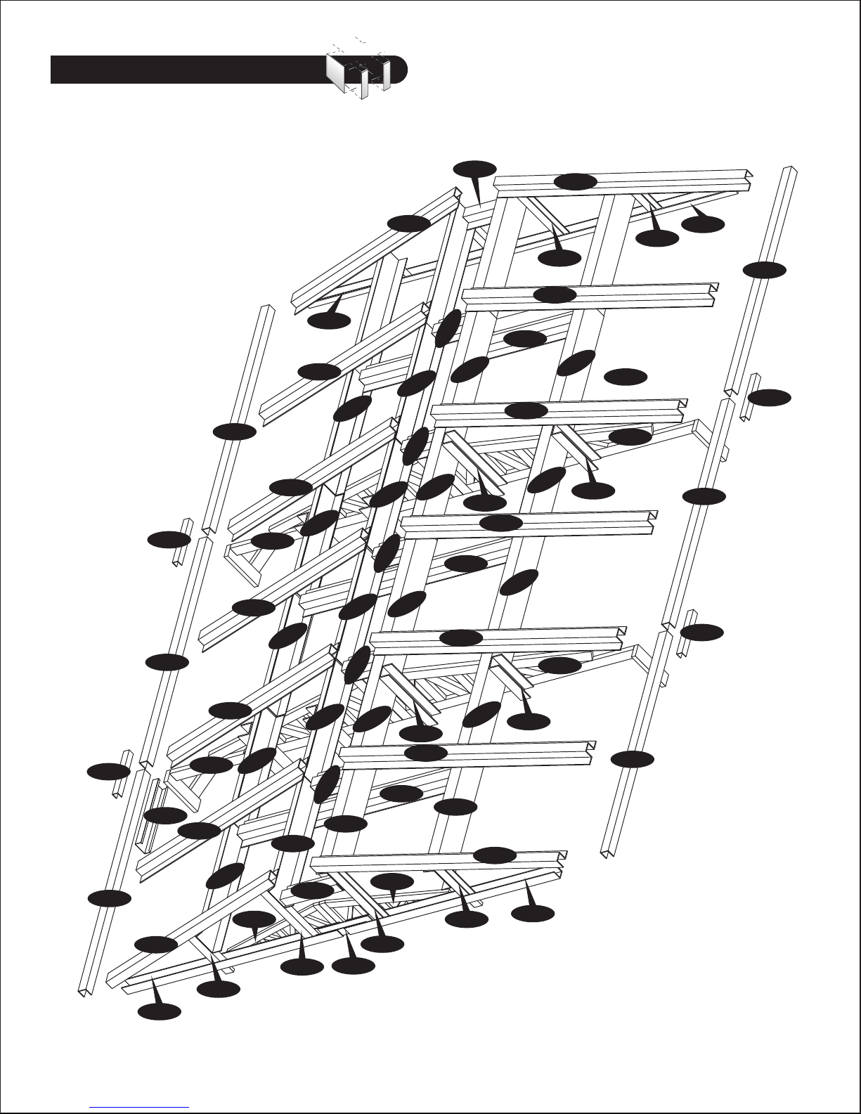
ROOF STRUCTURE
(RS5A)(RS6H) (RS7H)
ROOF STRUCTURES (RS - 1H,
3LH, 3LA, 8H, 9H,19H,20H) (CB-
1A,1H, 2A, 3A, 4A,4H,6H) (MJ)
PVC 90 DEGREE JOINT
(RJ)
ROOF SUPPORT (RS2A)
(RS10A) ROOF SUPPORT (RS4XA)
(RS11A) (RS12A)
MIDDLE COLUMN FITTING
(FMC)
CORNER COLUMN FITTING
(FCC)
LEFT DOOR COLUMN
(CDLA) (CDLH)
CORNER COLUMNS (CCA)
RIGHT DOOR COLUMN
(CDRA) (CDRH)
DOOR STOPPER
(DSHH)
CENTER BAND FITTING
(FCB)
DOOR COLUMN FITTING
(FDCL) DOOR COLUMN FITTING
(FDCR)
DOOR COLUMN FITTING
(FDCLC) DOOR COLUMN FITTING
(FDCRH)
ROOF PLUG WITH
WASHER (PPG)
ROOF PIN (PIN) END PLUG SQUARE (EPS)
SAGGING SUPPORT (RS14A) CENTER BAND COVER (CBC) TOP CORNER
(TCH)
MACHINE SCREW
(S3)
SHEET METAL SCREW
(S1), (S2), (S7)
FOUNDATION ‘L’ ANGLE
(F03)
FOUNDATION ‘U’ CHANNEL
(F01H,2H,3H,F04A,5A,6A,F07)
RAMP (RG)