Durst LABORATOR 184 User manual

Instructions for:
LABORATOR 184
Counter-weight spring adjustment.
DURST-PRO-USA, Inc.
1600 NE 25th Avenue
Hillsboro, Oregon 97124
USA
Phone 503 846 1492, fax 503 640 1878
www.durst-pro-usa.com
email:[email protected]


WARNING!
Working with the counterweight spring in a Durst Laborator 184, Laborator
138SP, or Laborator 138S is extremely dangerous. There is a high risk for per-
sonal injury and damage to the equipment when working with this counter weight
spring.
The spring combined with the spring tool is capable of releasing an impact with a
force of more than 2000 pounds per square inch.
This manual is put at your disposal on the clear condition that DURST-PRO-
USA, Inc. their employees, owners, Durst-Italy, the original reseller and the origi-
nal manufacturer of the enlarger under no circumstances what so ever can be held
responsible for personal injury or damage to the equipment, this also holds true if
this manual is faulty, in case of personal injury or damage to the equipment.
Breaking the seal on this envelope, to access the manual, constitutes your full
consent to the above – if you do not consent DO NOT break the seal and return
the envelope for a full refund – return freight is free of charge using the DURST-
PRO-USA, Inc. UPS account # 6404XW.
This manual is issued to_________________________________
To avoid any responsibility, on your part, from third party claims we advice not to
duplicate or copy this manual.

WARNING!
DO NOT ATTEMPT TO CARRY OUT THE SPRING ADJUSTMENT
ALONE!
SPRING ADJUSTMENT IS A TWO-PERSON JOB.
If this person continues the travel of the tool in a downwards direction the force
of the spring will make the enlarger travel in the direction of the red arrow, it will
pull you of the ladder and possible hit you in the head with the end of the tool.
NEVER STAND IN THE LINE OF TRAVEL OF THE TENSION TOOL.

WARNING!
DO NOT ATTEMPT TO CARRY OUT THE SPRING ADJUSTMENT
ALONE!
SPRING ADJUSTMENT IS A TWO-PERSON JOB.
If this person continues the travel of the tool in a downwards direction the force of
the spring will make the enlarger travel in the direction of the red arrow, as soon as
you start the upwards motion. It will pull you of the ladder and possible hit you in
the head with the end of the tool. The force released by the tension tool is several
thousand pounds per square inch, enough to KILL if hit in the head or the face.

Thetwospringsinsidethespringhous-
ing are each 4” wide, 1/8” thick and
fastened to a ½” chrome steel axle.
The front plate on the spring housing
is 4mm thick plate aluminum. If the
springisallowedtouncoiluncontrolled
itwillknockoffthisplate,rippingALL
SIX 4mm screws from their sockets.
If the spring is uncoiled uncontrolled
it will crack the ½ to1” thick cast alu-
minum housing

On this picture you will see the effect
of a spring accident. The force of the
spring knocked the ½ - 1” thick alumi-
num housing almost ½ inch out of
shape.
If you look careful at the image below
you can see that the entire 10 pound alu-
minum housing has been knocked out
of shape by more than 1/4”. The alumi-
num housing is 1/2” thick at its thinnest
place. The force released by an uncon-
trolled spring is several thousand pounds

The correct way to work
SPRING ADJUSTMENT IS A TWO-PERSON JOB.
This is the correct way to operate the spring tension tool. The person hold-
ing on to the chassis should be able to exert a force equal to lifting approx 50
pounds.Please use your common sense when working with the spring.
Go slow and anticipate your next move.
DO NOT ATTEMPT TO USE AN ADJUSTABLE WRENCH FOR SPRING
TENSIONING

A)
REMOVE THE LIGhT HEAD FROM
THE ENLARGER and drive the head
carriage to its BOTTOM position, this
willmovethecameraoutofthewayandit
will ensure that the spring-wire is in its
most exposed position.
B)
In some cases it is necessary to remove
the camera also to access the wire behind
the half-moon shaped scale.
On some models the wire is situated be-
hind two large 10mm bolts behind the
scale, it is not possible to reposition the
wire without removing the scale.
MANUAL FOR SPRING TENSION
AND SPRING REPLACEMENT ON A
DURST LABORATOR 184.

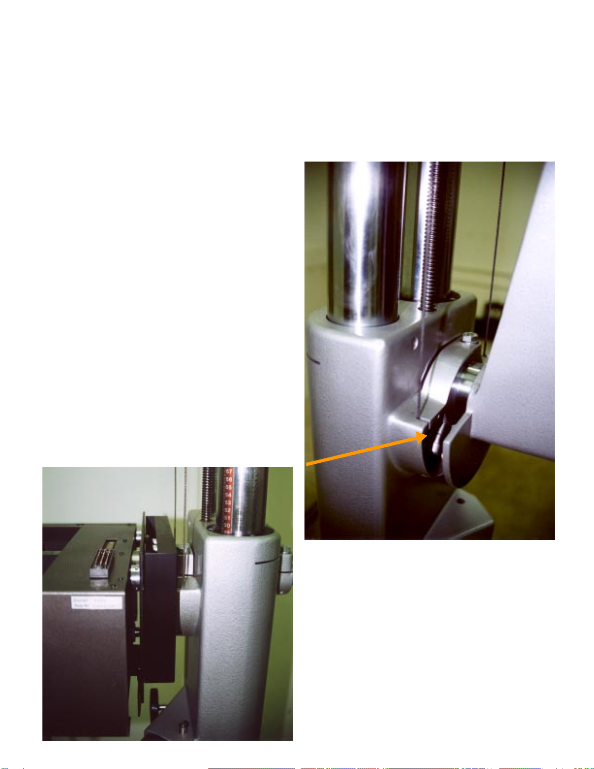
InordertoremovethecameraonanL184
it is only necessary to remove one screw.
When this screw is removed the camera
will slide off the support arm. Here it is
also helpful to be two persons, one per-
son to hold on to the chassis and one to
pull the camera off. The camera is quite
heavy, be careful not to drop it
The tool kit consist off:
1. Tension tool - 4 foot wrench w/
handle and stop.
2. Bolt to secure tool to spring hous-
ing.
3. “C” shaped ¼” steel bracket
4. Wire brace tool.
If a replacement wire has been ordered
the wire kit will be enclosed with the
tools. It is metric wire. It is important to
use the right thickness wire,
The wire is coiled up inside the wire
wheel.
If the wire is to thin it will break, and
ruin the spring housing, if it is to thick it
will not fit inside the wire wheel. An ex-
cess thickness of less than one millime-
ter – less than 1/32” of one inch – will
prevent the right amount of wire fitting
inside the wire wheel.
Remove the cover from both sides of the
spring housing.

1)
Move the enlarger head / head carriage
to it’s bottom position.
2)
Moving the head to to the bottom posi-
tion will thighten the counter weight
spring
2A)
.Continue by removing the cover from
the right side of the spring housing.
2B)
Please NOTE the round hole inside the
chrome axle. The axle is the round rod
inside the large nut. This hole is threaded
inside. The threads will accept the large
bolt which are part of the tool kit.

3)
Install the tension tool on the bolt on the
left side of the spring housing. Slide the
tool onto the chrome nut in a position
approximately as shown.
3A)
SECURE the tool with the enclosed 4”
long bolt, the bolt screws into the
threaded hole in the end of the chrome
axle.
MAKE SURE THAT YOU HAVE AN
ASSISTANT HOLDING ON TO THE
CHASSIS - THIS IS THE MOST
DANGEROUS POSITION OF THE
ENTIRE OPERATION.
The long tension tool will allow you to
excersise a force equal to several
hundrede pounds of lift and the
chassis is enclined to escape in the
direction of the red arrow.
4)
Turn the tool counter clockwise to a po-
sition where it is paralel with the chas-
sis and the wire is starting to slack.
Then have your assistant install the “C”
shaped bracket around the tool and the
column. You can hold on to the chassis.
5)
When the bracket is installed slowly let
go of the tenssion tool untill it is secured
by the “C” bracket in a position as shown
on the right.
The steel bracket has to be positioned in
such a manner that it will not SLIDE up
onthetool.Mostofour tools areequipped

with a cross rod for this purpose. If the
tool is not equipped with a cross rod use
tape or a rubber band to make sure that it
will not slide and loose the grip on the
tension tool.
This whole procedure is done with the
purpose of rendering the wire slack
enough to make it possible to remove the
wire on the right side of the spring hous-
ing.
6)
When the wire is slack it is possible to
remove the wire and the wire disk on the
right side of the spring housing.
First remove the screw and the disk hold-
ing the wire securely in place.
Then remove the pin sitting through the
axle and the nut using the pin extracter
enclosed with the tool set and a hammer.
The hammer is not supplied.
Thepinwillbeclearly thicker in one end,
it is important to knock it out by ham-
mering on the THIN end.
When the pin has been removed it is pos-
sible to remove the nut.
When the nut has been removed it is pos-
sible to remove the wiredisk. It is often
hard to remove the disk. The disk is at-
tached to the axcle with a pin on the back-
side. In order to disingage that pin it may
benecessary to manipulate thediskclock-
wiseandcounterclockwise,andpossible
tapping with a semi hard tool, a rubber

When the wire disk in the right side has
been removed and the wire hanging loose
itispossibletobring the tension tool back
to a position where it is parallel with the
column and then remove the “C” bracket.
7)
After the “C” bracket has been removed
it is possible to move the tension tool sev-
eral times clockwise until the spring in
completely slack and no tension is on the
tension tool.
While loosening the spring the existing
wire will be wound partly on to the wire
disk on the right side of the spring hous-
ing.
When this position is obtained the ten-
sion tool can be removed, the cover plate,
the nut and the wiredisk in the left side
of the spring housing can be removed.
After the left wire disk has been removed
it is possible to remove the old wire and
install a new fresh wire.
Please notice that the nut is NOT sym-
metrical, it is important to reinstall the
nut with the same side facing the spring
housing as was facing the spring hous-
ing before you removed it. If this little
detail is ignored it will not be possible to
align the pin hole in the nut with the pin
hole in the axle.
8)
THE NEW WIRE:
1) Install the nut on the left side of the
spring housing without any wiredisk in
place in either side of the head.
11) Tighten the spring entirely without
any wire disks installed in either side.
A)Release the spring 0.5 to 1 turn.
B) Install the “C” bracket.
13)install the wire disk in the right side
of the spring housing
To install the right wire disk you have to:
A) Secure the wire to the wire disk by
threading it through the hole in the disk,
create a wire loop and seal it with a cop-
per brace using the wire tool enclosed
with the tool kit, and finally securing the
wire loop with the screw and a thick
washer.
B) thread the wire through the hole in the
spring housing
C) install the wire disk on the axle by
threading the loose end of the wire
throughthehole in the spring housing and
angling the wire disk in place.
D) Refit the nut and the pin in the nut.
14)slack the spring entirely, or until the
wire taken up block further movement,
thus taking up the wire on the wire disk,
make sure that you keep the wire tight at
all times because the space is so limited
inside the spring housing that even the
least bit of slop will get the wire caught
between the disk and the spring housing.
15)Move the tension tool to the side
with the disk installed.
16)Retighten the spring using the ten-
sion tool. While doing so the wire that
was just wound up is now being exposed.
While the wire is being exposed it is im-

portant to keep the wire tight. If it gets
caught between the spring housing and
the wire disk it will get “kinked” and you
will have to start all over again.
A) When the spring is completely tight-
ened secure the tension tool using the “C”
bracket
B) Remove the nut in the left side of the
spring housing.
C) Thread the wire through the slots in
the camera carriage and through the hole
in the spring housing.
17) Thread the wire through the wire
wheel and slide the wire wheel in place
while
18)Pull the wire tight to make sure that
it remains without any “kinks”.
19) Secure the wire to the wire disk by
creating a copper sealed wire loop and
finally securing the wire loop with the
screw and a thick washer.
Replace the nut and the pin.
19) Replace the whire wheel covers.
Now the spring is completely tightened
with the camera in the lowest position.
This is ideal.
You are finished.
Onefinalremark - make sure thatthewire
is completely secured in both wire disks.
If not - it will slip and the spring will un-
coils it self and destroy the spring hous-
ing.
Good luck.

RESUME:
1) Head carriage in bottom position.
2) Spring is tight.
3) Install tension tool
4) Turn to slack wire.
5) Secure tension tool with “C” bracket.
6) Remove wire disk in opposite side of tension tool.
7) Slack spring until it is fully slack or blocked by wire taken up.
8) Install nut and pin in side without wiredisk installed.
9)Move tool to opposite side - the side with no wire disk and where
you just installed the nut and pin.
10) Tighten slightly to allow the second wiredisk to be removed.
11) after both wire disk are removed tension spring fully.
12) Install the new wire in the wire disk
13) Install wire wheel in opposite side of tension tool.
14) Release the spring until spring is completely slack or blocked
by the wire taken up.
15) move the tension tool to the side with the wire wheel installed.
16) Tighten spring completely or until further motion is blocked by
the wire taken up
17)thread wirethrough theheadcarriageloopand throughthe spring
housing.
18) pull the wire tight while sliding last wire wheel into position.
Avoid kinks.
19) install and secure wire in wire wheel.
20) replace wire wheel covers.
end.

Note.
It is possible to simplify the process by using the locking feature built into the
spring housing.
The two screws indicated with arrows are lock screws that can be used to lock the
two wire wheels in position, one at a time, without using the tension tool to lock the
spring.
These screws are prone to fail under strain and we strongly advice against using the
set screws.

Other Durst Industrial Equipment manuals