Durston Tools Quad Ringer User manual


1
These instructions contain very important safety information.
Please read them carefully before use.
The Quad Ringer is manufactured to help you to mass product jump rings using
non-ferrous jewellers’ metals like silver, copper, brass and gold. These instructions
are for using non-ferrous materials. The Quad Ringer is used with a flex shat
machine and Foredom no. 30 style handpiece. Excellent results can be achieved
for wire diameters in the range 0.8 to 1.5 mm. Wire diameters beyond this range
may be possible once you become more experienced with your ringer.
The supplied mandrels allow you to produce coils between 2.5mm to 12.0mm
inner diameter. The coil holder allows coil lengths of up to 100mm in length.
You are advised to practice on copper wire before committing to full length coils
of precious metals such as silver and gold. This will confirm that your set up is
correct. It is also good practice to cut short test coils of new sizes before
committing to full length coils.
For best results use fully annealed (dead soft) wire, but good results can be
achieved using harder tempers of silver, gold filled and solid gold wires with
practice. The thicker the wire, the more important that the wire be annealed.

2
Always wear eye protection. The coil winder can be permanently mounted to a bench or wall if you have
sufficient studio space. Alternatively, the coil winder can be mounted in a vice.
1. Select a mandrel that will be the inside diameter of your
jump rings. Insert the selected mandrel into the keyless
chuck with the wire holding hole just out of the chuck
jaws. Tighten the chuck.
2. Make a right-angle bend at the end of your wire and insert
it between two of the chuck jaws (or into the wire holding
hole –mandrels 4.5mm and above). Hold the wire firmly
in your left hand and turn the coil winder clockwise (up at
the front and down at the back) with your right hand.
3. Hold the wire against the coil (slightly to the right of the coil
end) to ensure a tight coil. A tight coil is necessary to make
good jump rings. Do not wind to the very end of your wire
as tension in the coil needs to be released carefully to avoid
injury to your fingers.
4. Remove the coil and trim the ends.
Making a Coil

3
It is very important that the blade turns in the correct direction when cutting the coil. Failure to follow
these instructions will result in poor results and could be hazardous.
The arrow on the saw blade must point in the
directions shown when assembling the blade
holder. Once the blade holder has been assembled,
place into your Foredom H30 handpiece.
Safety: Do not connect it to your flexshaft yet.
Slide the handpiece into the handpiece holder, with
the blade going in last.
Place the coil holder lid over the blade. Ensure that
the coil holder lid is pressed to the edge of the
handpiece holder and the blade is in the centre of
the slit in the coil holder lid. Tighten the grub screw
to hold the handpiece in the handpiece holder. Do
not over tighten, a 3mm allen key/wrench is
required.
Note the direction of the blade when in use and the
direction of the saw teeth.
Preparing the Blade Holder

4
Place your coil of wire in the coil holder. Use the
deepest channel so that the coil just stands
proud of the top of the channel. Apply Durston
Lubricant (or burr lube) along the top of the coil.
Push the coil up to the stop pin.
Attach the lid. Press the lid onto the coil and
hand tighten the screws evenly so that the lid
just starts to arch.
It can be helpful to place a small piece of
wooden dowel (trimmed to the outer diameter
of the coil) between the coil and the stop pin.
Place the coil holder firmly in a vice so that the
coil in the holder is closest to your body.
Cutting the Coil

5
Important!
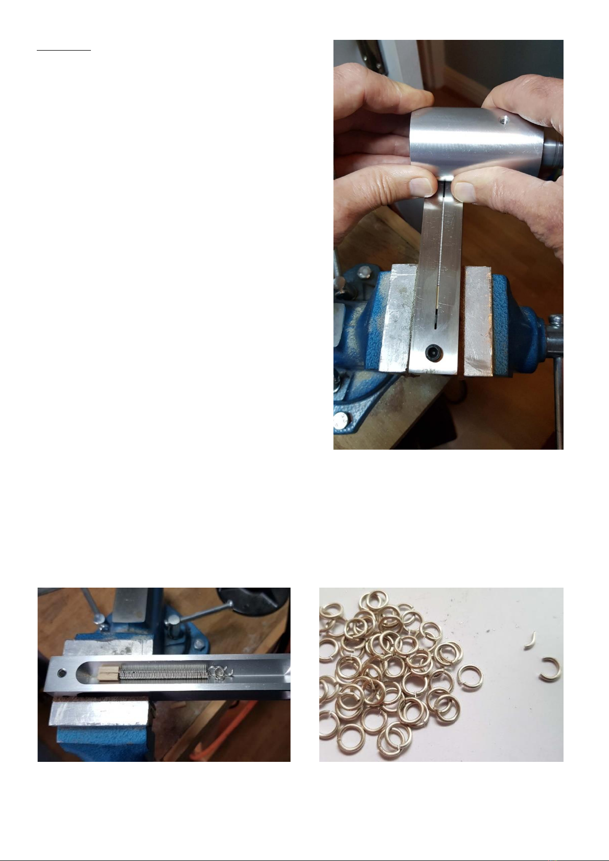
Hold the handpiece firmly and attach the flexshaft keeping
your hand and body clear of the blade.
Check that the motor is set to FORWARD (FWD).
Position the handpiece and blade holder at the end of the
coil holder furthest from your body in your right hand. The
stop pin end is closest to your body.
Start the motor at a medium speed. Keep the handpiece
holder horizontal and press the handpiece holder against
the left-hand side of the coil holder. Using two hands pull
the handpiece holder towards you. Adjust the motor
speed (if using a foot control) to maintain a constant motor
speed. When you reach the end of the cut stop the motor.
Wait until it has stopped completely before removing it.
Carefully remove the handpiece from the flexshaft.
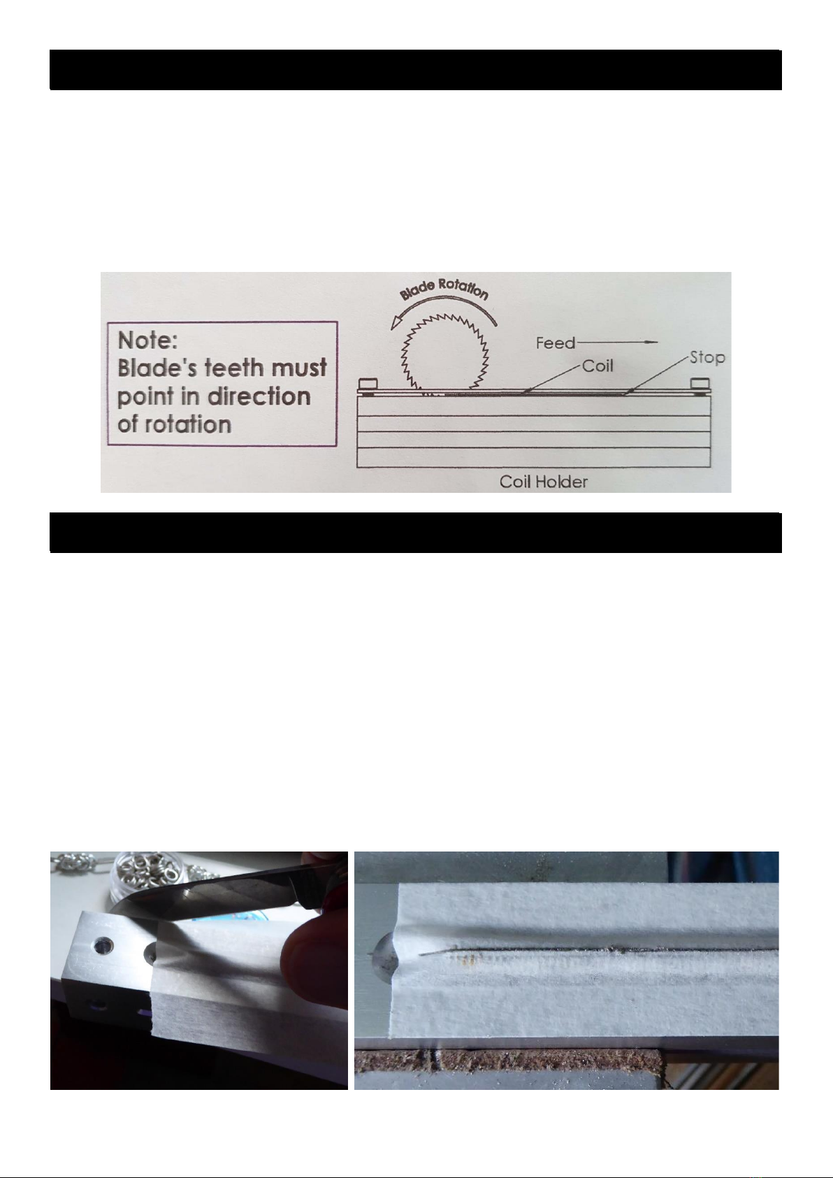
Note to left-handed users.
Complete the set up as described. This time you will put
the coil holder in the vice with the stop pin end furthest
away from you and handpiece in your left hand. Starting
at the end of the coil holder nearest to you, cut the coil by
pushing the flexshaft holder away from you.
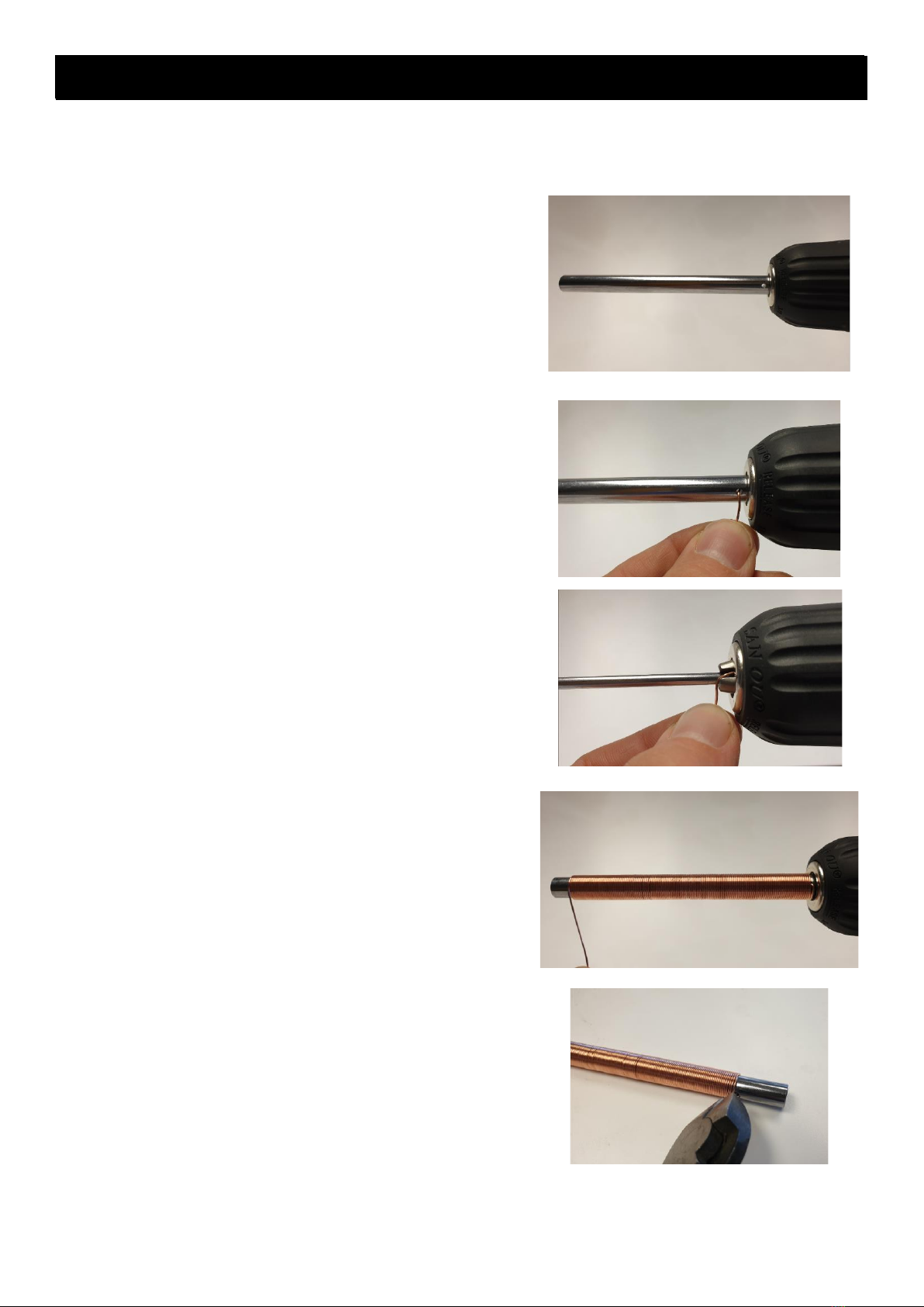
Finally, remove the jump rings from the coil holder.
The jump rings can be cleaned in an ultra-sonic cleaner and deburred in a tumbler as required. The jump rings
shown have an internal diameter of 4.5mm using 1mm sterling silver wire. A wooden dowel was used to
support the end of the coil at the end of the cut. The waste is shown on the right of the right-hand photo
below.

6
•Wear eye protection
•This is a high-speed cutting tool and could lead to serious injury if not used correctly
•Observe all safety instructions
•Attach the handpiece to the flex shaft only when you are making your cut and remove immediately
after use
•The blade must be set to that it cuts the coil upwards against the coil holder lid
•Check that the motor is set to Forward
The cut is not smooth
If your blade is not cutting smoothly stop the motor immediately and check you have set up your ringer
correctly. This will avoid spoiling the whole coil. Check your blade for wear/damage.
The final part of the cut fails
If the coil collapses at the end of the cut this is because the coil is not fully supported by the stop pin. Use a
piece of dowel trimmed to match the diameter of your coil as shown in the instructions.
Rings shoot out of the coil holder
Use the deepest channel available so the coil is just above the top side of the coil holder. A piece of masking
tape over the coil will help to keep the jump rings in the coil holder. Trim excess tape from the sides of the
holder.
Place the coil holder lid over the coil and tape.
Remember
Problem Solving

7
The blade breaks –most likely caused by incorrect use or using worn/damaged blades
Ensure that the blade is in the centre of the coil holder lid.
Hold the handpiece holder against one side of the coil holder with both hands and do not allow it to twist
during the cut. Keep it horizontal.
Check your saw blade does not have broken teeth and replace when it is wearing out.
Use Durston/burr lube every time to prolong the life of your blade.
Check that your blade will turn in the correct direction during the cut.
The coil slides away in the coil holder and is damaged
Motor in reverse! Always check your motor is set to Forwards before use.
The coil has a double cut
Ensure that you complete the cut with one smooth action. If you stop the motor during the cut do not start
up again. Remove the coil and rings from the holder and set up the remaining part of the coil up again.
Conversion Tables
American
Wire Gauge
Diameter
(AWG)
(mm)
14
1.63
15
1.45
16
1.29
17
1.15
18
1.02
19
0.91
20
0.81
21
0.72
22
0.65
23
0.57
24
0.51
Calculating the length of coil required for x jump rings.
Example:
50 jump rings are needed from 1mm wire.
Make a coil 50 x 1 = 50mm plus 2 to 4mm extra
50 jump rings from 1.3mm wire.
Make a coil 50 x 1.3 = 65mm plus 3 to 6 mm extra
Using square wire
Do not allow the wire to twist when forming the coil. Hold the wire in parallel pliers and wind the coil slowly
and carefully so that the flat side of the wire is firmly against the mandrel.
Standard
Wire Gauge
Diameter
(SWG)
(mm)
16
1.626
17
1.422
18
1.219
19
1.016
20
0.914
21
0.813
22
0.711
23
0.61
24
0.559
25
0.508
26
0.457
Further Notes and Tips

8
Description
Ordering code
Ringer Mandrel 2.5
9214
Ringer Mandrel 3
9215
Ringer Mandrel 3.5
9215
Ringer Mandrel 4
9217
Ringer Mandrel 4.5
9218
Ringer Mandrel 5
9219
Ringer Mandrel 5.5
9220
Ringer Mandrel 6
9221
Ringer Mandrel 6.5
9222
Ringer Mandrel 7
9223
Ringer Mandrel 7.5
9224
Ringer Mandrel 8
9225
Ringer Mandrel 8.5
9226
Ringer Mandrel 9
9227
Ringer Mandrel 9.5
9228
Ringer Mandrel 10
9229
Ringer Mandrel 10.5
9230
Ringer Mandrel 11
9231
Ringer Mandrel 11.5
9232
Ringer Mandrel 12
9233
Coil Holder Lid
9235
Blade Holder
9236
Flexshaft Holder
9237
Coil Holder
9238
Mandrel Holder
9239
Spare Blade
9303
Parts Breakdown


Thank you for purchasing the
Durston Quad Ringer.
With the correct use it will give you many years
of service.
This manual suits for next models
1
Table of contents