BIO-FIGHTER®XL INSTALLATION & OPERATION MANUAL
WARNING
UV Light Hazard.
Can cause serious eye and skin
damage.
Do not look at UV-C light. Wear UV-C
eye and skin protection.
SPECIAL INSTALLATION NOTESUNPACKING
PLACEMENT
Do not install in closet return grille
applications.
Do not expose wiring or plastic parts to
UV-C light.
Do not install where UV-C light can be seen
after installation.
Do not install beneath a humidifier.
If the UV device is installed on the inlet side
(return air side) of a coil, make sure that
the HVAC system is configured such that
the blower is located between the return
air filter and the inlet side (return air side)
of the coil, such as would be found in a
traditional upflow, or horizontal furnace with
the coil placed after the heat exchanger.
If the UV device is installed near an air filter,
check with filter manufacturer for UV-C
resistance properties.
If the desired UV installation location
is intended to irradiate an air filter, to
neutralize the microbiological matter on
the air filter surface, such as would be
found in the return air drop of a basement
application or in the return plenum of
a horizontal system in an attic; take
precautions as described in note above,
and make sure the UV fixture is placed
on the return side of the filter. DO NOT
INSTALL THE UV FIXTURE ON EITHER
SIDE OF THE FILTER IN HALL / CLOSET
RETURN AIR APPLICATIONS. (See
ATTENTION! Warning sheet #212945-00).
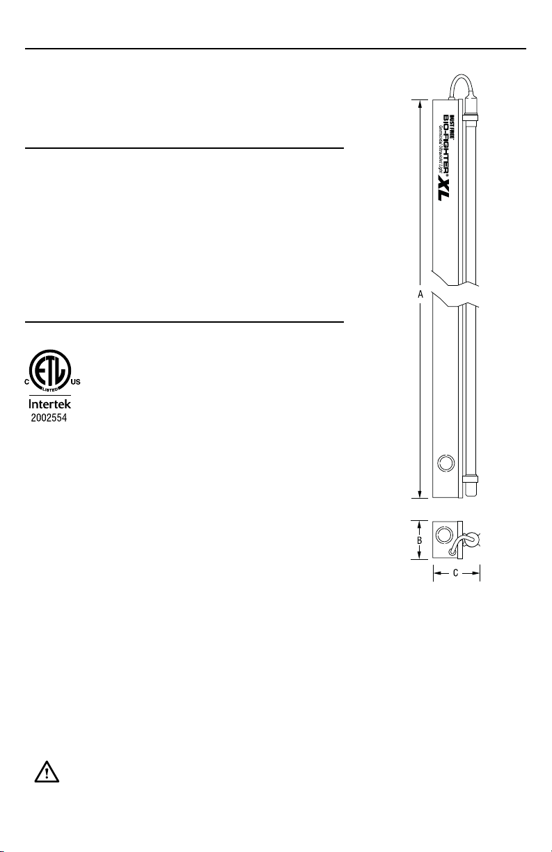
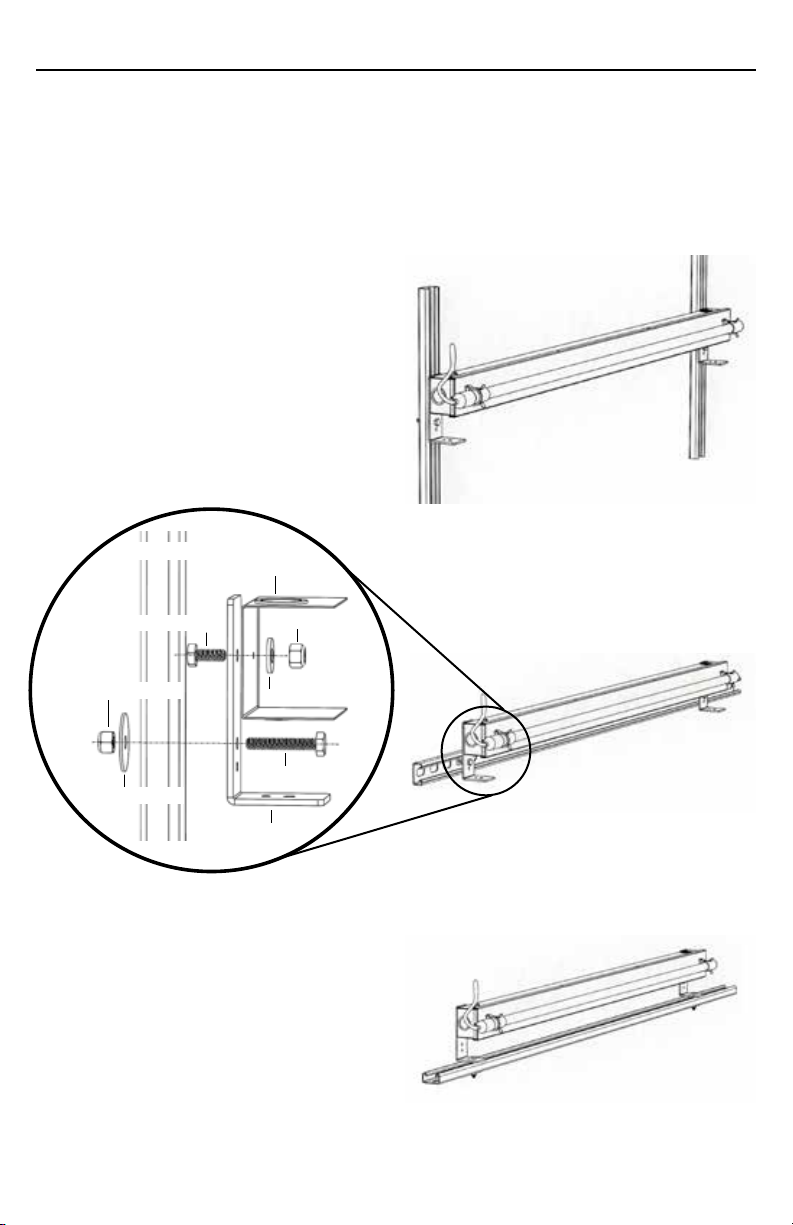
The Bio-Fighter® XL is packaged with a
clear protective film covering the polished
aluminum reflector. This film must be
removed prior to operation. First remove
the lamp from the lampholders and lay
to the side. Then peel the film from the
reflector.
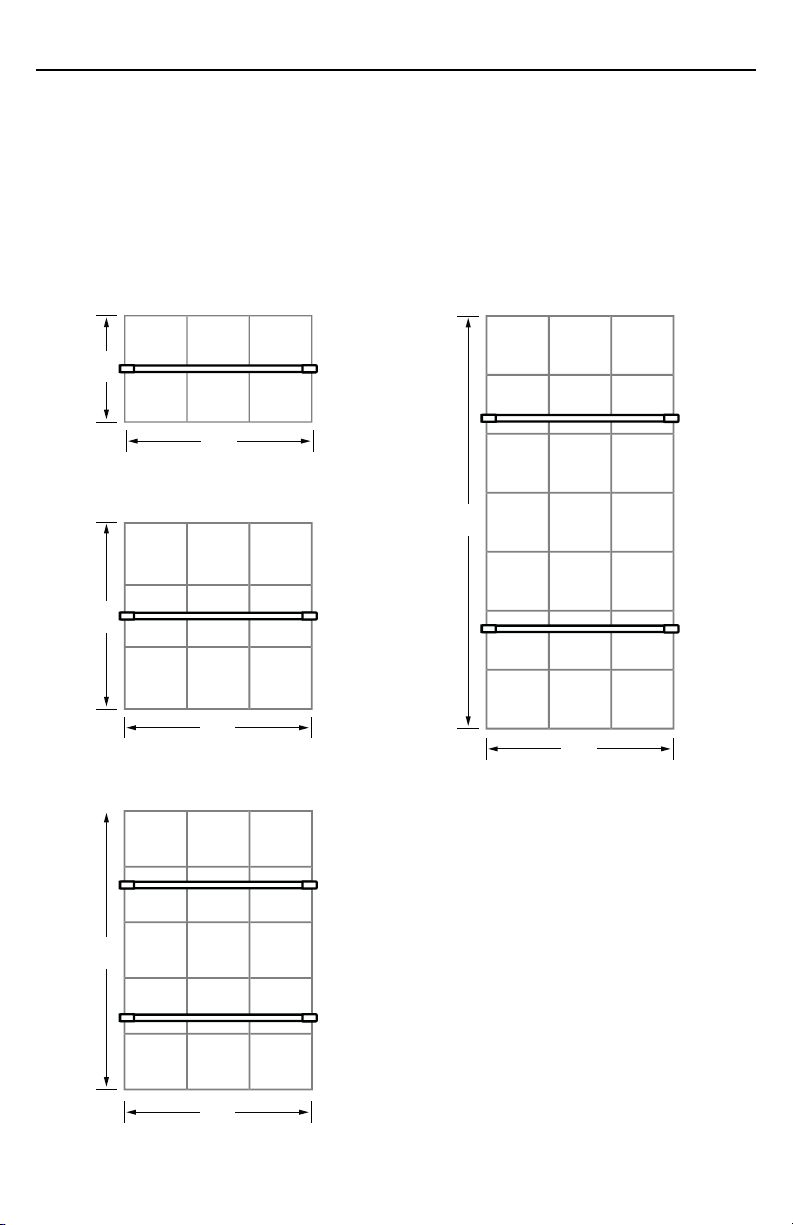
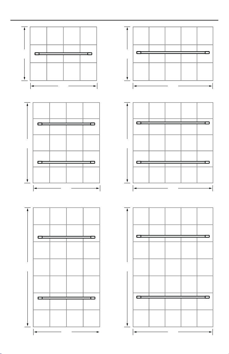
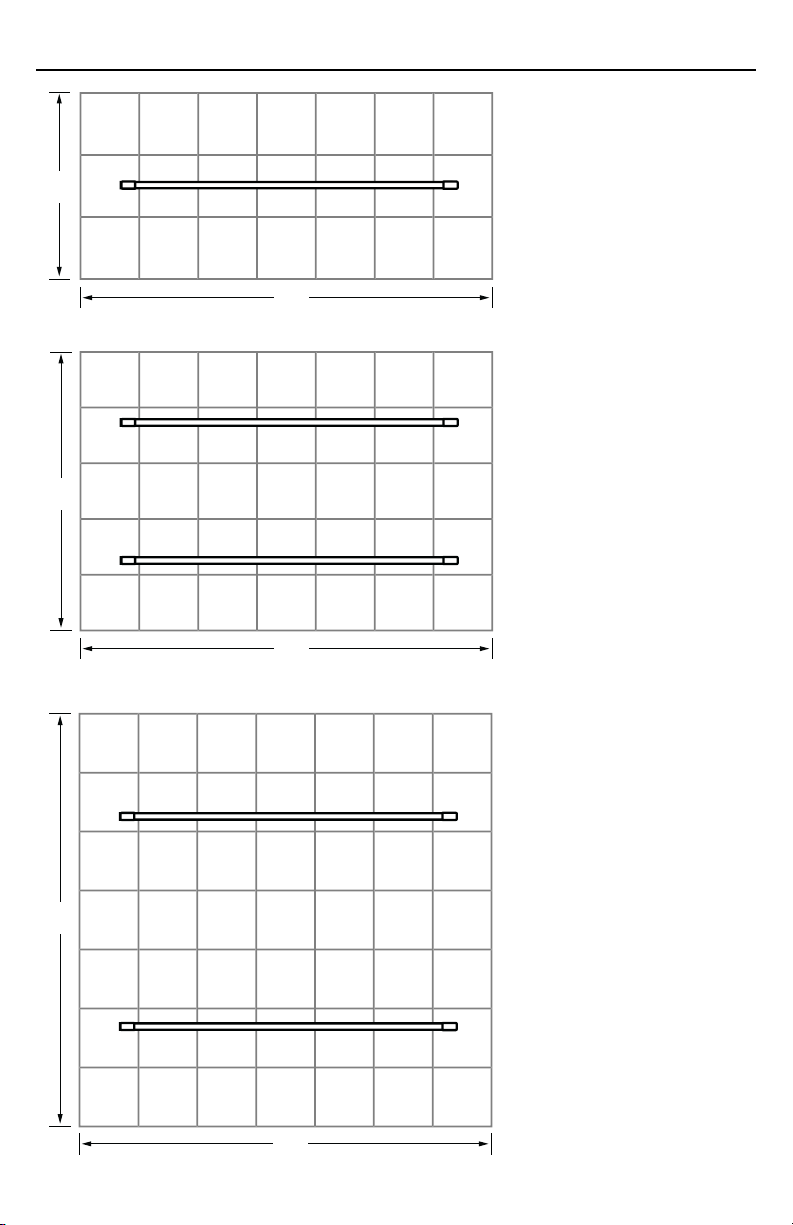
Each foot of fixture length will irradiate a
three square foot area. For example, one
five foot Bio-Fighter®XL can irradiate 15
square feet of surface area. To maximize
efficiency of the UVC light, each fixture
should be placed 18-22 inches from the
surface to be irradiated. Ensure no plastic
parts or wire insulation is exposed, and that
wherever the unit is placed, no light can be
seen after installation.
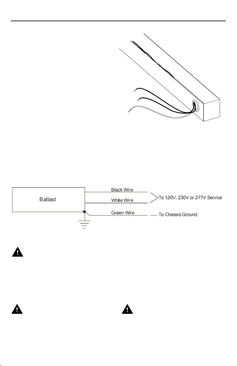
WARNING
Electric Shock Hazard.
Can cause injury or death.
Electrical wiring of the unit to the
HVAC system should be done by a
licensed HVAC technician or
electrical installer.