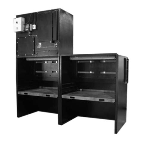
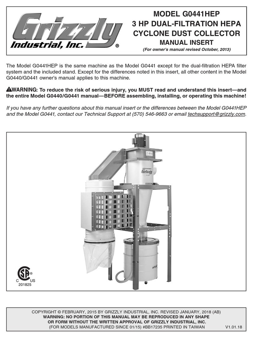
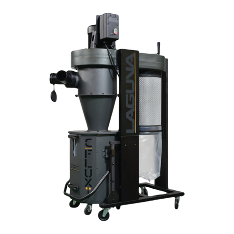
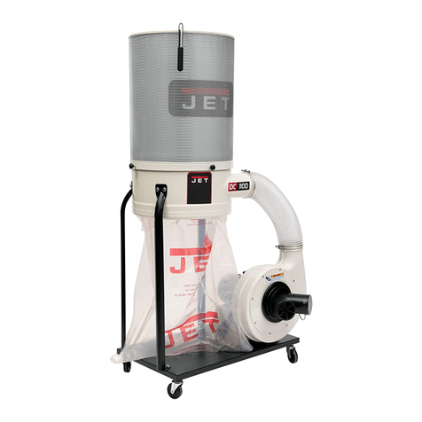
Dust-Hog SUPRA-CONIC User manual

SUPRA-CONIC®
Cartridge Dust Collector
Installation and Operation Manual

KNOW YOUR EQUIPMENT
READ THIS MANUAL FIRST.
Your DUST-HOG®SUPRA-CONIC®system should provide many years of trouble-free
service. This manual will help you understand the operation of your DUST-HOG®unit. It will
also help you understand how to maintain it in order to achieve top performance. For quick
future reference, fill in the system and filter information in the spaces below. Should you
need assistance, call the DUST-HOG®customer service number shown below. To expedite
your service, have the following information available when contacting UAS.
UAS ORDER #: ________________________________________________________________
UNIT MODEL #:________________________________________________________________
UNIT SERIAL #:________________________________________________________________
CARTRIDGE FILTER PART #: ____________________________________________________
SYSTEM ACCESSORIES:
______________________________________________________________________________
______________________________________________________________________________
______________________________________________________________________________
INSTALLATIONDATE: __________________________________________________________
DUST-HOG®CUSTOMER SERVICE
1-800-252-HOGS

i
TABLE OF CONTENTS
Page
SAFETY PRECAUTIONS.........................................................................................iii
1. IMPORTANT NOTICE.........................................................................................1
2. INTRODUCTION.................................................................................................1
2.1 Unit Nomenclature ........................................................................................1
2.2 Description and Operation ............................................................................1
2.3 Air Filtering Operation ...................................................................................1
2.4 Filter Cleaning Cycle.....................................................................................1
3. SUPRA-CONIC®SPECIFICATION TABLE.........................................................5
4. INSTALLATION...................................................................................................5
4.1 Inspection Note .............................................................................................5
4.2 Off Loading and Inspection...........................................................................5
4.3 Installation Planning......................................................................................5
4.4 Electrical Installation and Controls Configuration.........................................6
4.4.1 Electrical Air Pulse Cleaning Control System with
Customer-Supplied Motor/Blower Starter Controls.............................6
4.4.2 Electrical Air Pulse Cleaning Control System with
Manual Motor/Blower Starter Controls................................................7
4.4.3 Combination Electrical Air Pulse Cleaning Control System and
Magnetic Motor/Blower Starter Control Package................................7
4.4.4 Electrical Air Pulse Cleaning Control System Less Air Compressor
with Customer-Supplied Motor/Blower Starter Controls......................7
4.4.5 Electrical Air Pulse Cleaning Control System Less Air Compressor
with Manual Motor/Blower Starter Controls.........................................8
4.4.6 Combination Electrical Air Pulse Cleaning Control System Less Air
Compressor and Magnetic Motor/Blower Starter Control Package....8
4.5 Standard Dust Collection Configuration......................................................13
4.5.1 Dust Drawer Assembly......................................................................13
4.5.2 Hopper Assembly ..............................................................................13
4.5.3 Bin Vent Assembly.............................................................................13
4.6 Drum Lid Kit Installation for Hopper Assemblies ........................................13
4.7 Inlet Collar and Blank Cover Plate Installation ...........................................13
4.8 Standard Printed Circuitboard Configuration (Factory Settings).................13
4.9 Self-Contained Compressed Air Cleaning System .....................................15

ii
TABLE OF CONTENTS (cont.)
5. OPERATION.....................................................................................................15
5.1 Start-Up.......................................................................................................15
5.2 Checklist......................................................................................................17
5.3 Downtime Cleaning Adjustment Settings on Printed Circuitboard..............18
6. SERVICE...........................................................................................................19
6.1 Cartridge Filter Removal and Replacement................................................19
6.2 Cartridge Filter Seeding Procedure ............................................................20
6.3 Dust Removal..............................................................................................20
6.4 Servicing the Direct Drive Motor and Blower Wheel...................................20
6.5 Servicing Optional Exhaust Air Safety Filters and HEPAAfterfilters...........20
7. OPTIONALACCESSORIES AND INSTALLATION INSTRUCTIONS...............20
7.1 Hopper Assembly........................................................................................20
7.2 Magnehelic®Gage.......................................................................................21
7.3 Caster Assembly (SC600 and SC1700 Models only).................................21
7.4 ASHRAE and HEPAAfterfilter Assembly....................................................21
7.5 Downdraft Bench Assembly (SC1700 model only).....................................21
7.6 Open Bin Vent Assembly ............................................................................21
7.7 Inlet Gate Assembly....................................................................................29
7.8 Pneumatic Valve Assembly Kit....................................................................29
7.9 Remote Blower Start/Stop Assembly..........................................................29
7.10 Dust Re-Entrainment Baffle ......................................................................29
7.11 Prefilter......................................................................................................29
7.12 On-Site Compressed Air Supply ...............................................................30
8. TROUBLESHOOTING GUIDE..........................................................................31
9. ILLUSTRATEDPARTS......................................................................................34
SC600 Bill of Materials......................................................................................35
SC1700 Bill of Materials....................................................................................36
SC3400 Bill of Materials....................................................................................37

IMPORTANT SAFETY INSTRUCTIONS
To reduce the risk of fire, electric shock, or injury when using your air cleaner, follow these basic precautions:
iii
SAFETY PRECAUTIONS
We have provided many important safety messages in this manual and on your PORTA-HOG®air cleaner. Always read and
obey all safety messages.
• The air cleaner must be properly grounded.
• Disconnect power before servicing.
• Replace all access panels before operating.
• Wear protective clothing and safety glasses when handling
collection components or servicing the air cleaner.
• Electrical connections should only be made by qualified
personnel, and be in accordance with local and national
codes and regulations.
• Avoid mixing combustible materials, such as aluminum,
paper, wood or other organic dusts with dusts generated
from grinding metals. A fire hazard could develop from
sparks entering the dust collector.
• Consult national and local fire codes, waste disposal,
safety and other appropriate authorities and comply with
their recommendations for the proper installation and
operation of dust collection equipment.
• Do not use in explosive atmospheres.
• Use nonflammable cleaners.
• Do not collect emissions which are explosive.
• Keep flammable materials and vapors, such as gasoline,
away from air cleaner.
• The unit should be inspected frequently and dirt removed
to prevent excessive accumulation which may result in
flash-over or fire damage.
• When collecting emissions from spark-producing process-
es, care must be taken to reduce any potential fire haz-
ards. System design should include methods to prevent
sparks from entering the dust collector. Dust collectors do
not contain fire extinguishing equipment.
• Operate only in a safe and serviceable condition.
!
!D A N G E R
!WARNING
!WARNING
!C A U T I O N
C A U T I O N
This is the safety alert symbol.
This symbol alerts you to potential hazards that can kill or hurt you and others. All safety messages will follow the
safety alert symbol and the word “DANGER”, “WARNING”, or “CAUTION”. These words mean:
Indicates a hazardous situation which, if not avoided, will result in death or
serious injury.
Indicates a potentially hazardous situation which, if not avoided, could result
in death or serious injury.
Indicates a potentially hazardous situation which, if not avoided, may result
in minor or moderate injury.
CAUTION used without the safety alert symbol indicates a potentially
hazardous situation which, if not avoided, may result in property damage.

United Air Specialists, Inc.
Revised 9/02 Porta-Hog®
Supra-Conic®Cartridge Dust Collector
1. IMPORTANT NOTICE
This manual contains important safety information and
precautionary measures. It is impossible to list all
potential hazards associated with every dust collection
system in each application. Proper use of the equipment
must be discussed with United Air Specialists, Inc. (UAS)
or your local DUST-HOG®representative. Operating
personnel must be aware of, and adhere to the most
stringent safety procedures.
2. INTRODUCTION
Thank you for selecting DUST-HOG®dust collection
equipment to assist you in your commitment to a clean
and safe environment. We trust that in purchasing our
product you have recognized our commitment to
continually offer dust collection equipment engineered to
the highest standards.
The Supra-Conic®dust collector is designed to collect
process-generated dusts. The Supra-Conic®is a
high-efficiency, intermittent-duty, small cabinet cartridge
collector equipped with an exclusive UAS conical
cartridge filter with air distribution insert. Each
Supra-Conic®unit is also equipped with a self-contained,
reverse air pulse cleaning system.
The Supra-Conic®dust collector should not be used for
any purpose not listed in this manual. Refer to Figure 1
for overall Supra-Conic®dimensional information for dust
drawer model configuration.
As you review this manual, refer to Figure 2 for
assistance in locating unit parts.
2.1 UNIT NOMENCLATURE
Example: SC600
SC-DUST-HOG®Supra-Conic®small cabinet cartridge
collector models
1
Model Number
SC600
SC1700
SC3400
Filter System
Single
cartridge
Single
cartridge
Dual
cartridge
Airflow (Nominal)
400-700 CFM
(700-1,200 m3hr)
700-1,800 CFM
(1,200-3,000 m3hr)
1,800-3,400 CFM
(3,000-5,700 m3hr)
2.2 DESCRIPTION AND OPERATION
The DUST-HOG®Supra-Conic®is a high-efficiency,
cartridge dust collector designed for intermittent-duty
collection. The Supra-Conic®is equipped with a filter
cleaning system developed by UAS. The cartridge filter
is a conical filter with an integrated air distribution insert.
The filter is arranged in a vertical orientation to
precipitate contaminant release from the pleated filter
design. The dust collector is designed for automatic
downtime filter cleaning by means of a built-in
compressed air system (refer to Figure 2).
There are two primary modes of operation — the air
filtering operation and filter cleaning cycle (refer to
Figure 3).
2.3 AIR FILTERING OPERATION
The Supra-Conic®is a compact, high-efficiency, vertically
orientated dust collector equipped with a cone-shaped
cartridge filter. The unit includes a backward-inclined fan
wheel for quieter operation and higher airflow
performance, as well as a self-contained air pulse
cleaning system designed for downtime cleaning.
The contaminated airstream enters the dust collector
through the rear and/or side inlets. The airstream
velocity is reduced and channeled by a series of inlet
baffle plates which produce even dust loading distribution
across the conical cartridge filter(s). The conical shape
of the filter provides increased media surface area along
with an inherently lower pressure drop across the filter.
This allows greater external static pressure capabilities
and requires less horsepower (kilowatts) to run. The
filter media strips the dust from the airstream allowing
only the clean air to pass through the filter. The clean
airstream then moves through the tubesheet into the
lower blower chamber compartment which houses a
Goyen®diaphragm valve. The clean airstream is pulled
upward through a backward-inclined blower wheel and is
exhausted out the top of the cabinet.
2.4 FILTER CLEANING CYCLE
During normal operation of the intermittent-duty dust
collector, the surface of the cartridge filter(s) becomes
loaded with contaminants. Upon start-up, the downtime
filter cleaning system will automatically engage and the
air manifold is pressurized to 93 PSIG (6.5 BAR) by a
self-contained air compressor. However, the air pulse
blast does not activate until the unit is shut down. One
minute after the fan is deactivated, the diaphragm valve
will discharge 93 PSIG (6.5 BAR) of air into the center of
the conical filter for 0.5-1.0 seconds. The flexing of the
filter media and the pulse airflow breaks the collected
particles from the filter media and the particles fall
downward into the dust drawer, drum or pail. The
tapered design of the conical filter allow gravity to aid
particle removal and increase dust release.

Revised 9/02 Porta-Hog®
Supra-Conic®Cartridge Dust Collector
2
United Air Specialists, Inc.
FPO - Use new diagram provided.

Revised 9/02 Porta-Hog®
Supra-Conic®Cartridge Dust Collector
3United Air Specialists, Inc.

Revised 9/02 Porta-Hog®
Supra-Conic®Cartridge Dust Collector
4
United Air Specialists, Inc.

5United Air Specialists, Inc.
Revised 9/02 Porta-Hog®
Supra-Conic®Cartridge Dust Collector
4. INSTALLATION
4.1 INSPECTION NOTE
Upon receipt of your unit, check for any shipping
damage. A damaged carton indicates that the equipment
may have received rough handling during shipping that
may have caused internal damage. Notify your delivery
carrier and enter a claim if any damage is found.
4.2 OFF LOADING AND INSPECTION
Each Supra-Conic®unit is shipped completely assembled
on one skid. Another skid will contain the hopper/leg
assembly and other components. Other accessories
(afterfilters, assemblies, casters, storage drums, etc.)
may be on an additional, separate skid.
Hopper overall dimensional information can be found in
Figures 11, 12 and 13 in Section 7 of this manual.
Supra-Conic®dust collectors have high centers of
gravity due to the unique fan design. Extreme care
should be used when moving the collector to avoid
overturning the unit.
NOTE: Do not lay collector on its side or back as
damage to fan assembly may occur.
4.3 INSTALLATION PLANNING
Asolid, level surface is required for installation of a
standard Supra-Conic®dust collector. Acollector with
optional hopper assembly requires a level concrete
surface for installation. The concrete surface or pad is
3. SUPRA-CONIC®SPECIFICATION TABLE
Supra-Conic®Model
SC600 w/dust drawer
SC600 w/5 gallon (19 liter) pail
hopper assembly
SC1700 w/dust drawer
SC1700 w/30 gallon (114 liter)
drum hopper assembly
SC1700 w/55 gallon (208 liter)
drum hopper assembly
SC3400 w/dust drawer
SC3400 w/30 gallon (114 liter)
drum hopper assembly
SC3400 w/55 gallon (208 liter)
drum hopper assembly
Motor/Blower
HP (kW)
1.5 (1.1)
3 (2.2)
7.5 (5.5)
Filter Area
FT2(M2)
70 (6.5)
192 (17.8)
384 (35.7)
Filter
Quantity
1
1
2
Valve
Quantity
1
1
2
Unit
Weight
LBS (KG)
283 (128)
385 (175)
395 (179)
520 (236)
550 (249)
685 (311)
838 (380)
859 (390)
Maximum Sound
Power Noise Level
dB+
–5dB @ 5 ft. (1.5M)
73
79
85
usually reinforced. Refer to Section 4.5.2 and Section
7.1 for additional information on optional hopper
assembly installation requirements.
The Supra-Conic®dust collector is designed for indoor
operation and location only. The Supra-Conic®is
designed to operate at a maximum indoor temperature
environment of 100°F (38°C).
The built-in air compressor is designed to operate in
a light-duty environment. Heavy or dirty environments
will cause the air compressor to malfunction and/or
fail prematurely. In heavy or dirty environments, it is
recommended the customer provide compressed air
to the dust collector manifold.
Locate the Supra-Conic®dust collector as close as
possible to the dust source.
Certain items should be considered when locating the
unit, such as room to empty the dust storage container(s)
(dust drawer, drum or pail), filter removal requirements,
electrical connections and fan discharge direction. The
shortest duct length with a minimum number of elbows
will maximize the performance of the unit. Ease of
maintenance should also be considered when selecting
the location and orientation of the system.
Do not locate dust collector near dust source in cases
where dust is explosive or a fire hazard.
Supra-Conic®dust collectors are not designed as
explosion proof and/or spark resistant units.
C A U T I O N
!WARNING
!C A U T I O N

6
United Air Specialists, Inc.
Revised 9/02 Porta-Hog®
Supra-Conic®Cartridge Dust Collector
In the case of spark producing producing processes,
system design should incorporate measures to prevent
live sparks from entering the dust collector. Consult local
authorities for the location of this unit and any
precautions to consider when collecting combustible,
explosive or hazardous dusts.
Interconnecting ductwork should be designed to include
a volume control damper(s) for regulating system design
airflows. UAS offers optional volume control dampers
which can be installed on the air inlet collar(s) of the
Supra-Conic®dust collector to regulate unit airflow.
Ductwork must be properly sized to meet the
recommended air velocities for the material being
collected.
Follow ductwork design methods as listed in the
Industrial Ventilation Manual as recommended by the
American Conference of Governmental Industrial
Hygienists.
NOTE: If the dust collector is to be operated with
multiple inlets, ductwork must be sized to meet
the recommended air velocities for the material
being collected. Low air duct velocities may
cause dust to settle out during normal operation.
4.4 ELECTRICAL INSTALLATION AND
CONTROLS CONFIGURATION
The Supra-Conic®dust collector can be factory ordered
to any of the following electrical configurations:
1. Electrical air pulse cleaning control system with
customer-supplied motor/blower starter controls (refer
to Figures 4, 5 and 6).
2. Electrical air pulse cleaning control system with manual
motor/blower starter controls (refer to Figure 6).
3. Combination electrical air pulse cleaning control
system and magnetic motor/blower starter controls
package (refer to Figures 4 and 5).
4. Electrical air pulse cleaning control system less air
compressor with customer-supplied motor/blower
starter controls (refer to Figures 4, 5 and 6).
5. Electrical air pulse cleaning control system less air
compressor with manual motor/blower starter controls
(refer to Figure 6).
6. Combination electrical air pulse cleaning control
system less air compressor and magnetic
motor/blower starter control package (refer to Figures
4 and 5).
Customer shall supply a motor starter package
configured to either Figure 4, 5 or 6 in accordance with
local electrical codes, regulations and directives.
All electrical work should be performed by a qualified
electrician in accordance with local electrical codes,
regulations and directives. De-energize and
disconnect electrical power before installing or
servicing any electrical equipment. Refer to Figures 4,
5 and 6 for wiring schematics.
NOTE: Amotor starter is required for blower (fan motor)
operation. The motor starter must be properly
sized to meet the incoming power voltage and
full load amperage of blower (fan motor)
assembly. Refer to fan motor nameplate for this
information. As an option, UAS can provide
factory-installed electrical package
configurations which include motor/blower
starter assemblies.
4.4.1 ELECTRICAL AIR PULSE
CLEANING CONTROL SYSTEM
WITH CUSTOMER-SUPPLIED
MOTOR/BLOWER STARTER
CONTROLS
Refer to Figures 4, 5 and 6 for electrical schematics.
The electrical air pulse cleaning control system with
customer-supplied motor/blower starter controls requires
the customer to supply a motor starter package for
starting the blower (fan motor) assembly. The electrical
air pulse cleaning control system installed on the unit
consists of the following major components: air
compressor, diaphragm valve, pressure switch with
unloader valve, check valve, interconnecting tubing and
fittings, air manifold reservoir, printed circuitboard
controller card and conical filter assembly.
The air pulse cleaning control system requires 500 watts
of 100-120V, single-phase, 50/60 hertz power supply to
operate. Aprinted circuitboard (PC) controller card is
housed inside an 8 1/2" H (22cm) x 7 1/2" W (19cm) x
2 1/2" D (6cm) electrical enclosure located on the rear
wall of the dust collector above the air manifold
reservoir. The 100-120V, single-phase power supply
must be connected to the PC board terminals L(+), N(-),
G(E) – L(+) designates line power connection, N(-)
designates neutral connection and G(E) designates
earth ground connection.
For the cleaning system to operate correctly, a
normally open (N.O.) auxiliary motor starter contact
(designated 1M-B in electrical schematics Figures 4,
5 and auxiliary of Figure 6) must be wired across
terminal block designations AUX MOT on terminal
block 3 (TB3) of PC board. Refer to Figure 7 for
printed circuitboard (PC) controller card layout.
C A U T I O N
!WARNING

7United Air Specialists, Inc.
Revised 9/02 Porta-Hog®
Supra-Conic®Cartridge Dust Collector
When ordering a motor starter contactor, make certain to
select a contactor which has two N.O. auxiliary contacts
(designated as 1M-A and 1M-B on electrical wiring
schematics). The Supra-Conic®will be delivered with the
following items pre-wired to the PC board controller card:
air compressor, diaphragm valve and pressure switch.
4.4.2 ELECTRICAL AIR PULSE CLEANING
CONTROL SYSTEM WITH MANUAL
MOTOR/BLOWER STARTER
CONTROLS
Refer to Figure 6 for electrical schematics.
3-PHASE INSTALLATION:
The electrical air pulse cleaning control system with
manual motor/blower starter controls requires the
customer to supply separate 3-phase and single-phase
power supplies. The blower (fan motor) assembly
requires 3-phase power supply and the electrical air
pulse cleaning system requires single-phase power
supply. The factory-supplied electrical air pulse cleaning
control system and manual motor starter packages are
installed on the dust collector. This package
configuration consists of the following major components:
manual motor starter with blower start/stop push buttons
in an enclosure, air compressor, diaphragm valve,
pressure switch with unloader valve, check valve,
interconnecting tubing and fittings, air manifold reservoir,
printed circuitboard controller card, and conical filter
assembly.
The air pulse cleaning control system requires 500 watts
of 100-120V, single-phase, 50/60 hertz power supply to
operate. The printed circuitboard (PC) controller card is
housed inside an 8 1/2" H (22cm) x 7 1/2" W (19cm) x
2 1/2" D (6cm) electrical enclosure located on the rear
surface of the dust collector above the air manifold
reservoir. The 100-120V, single-phase power supply
must be connected to the PC board terminals L(+), N(-),
G(E) – L(+) designates line power connection, N(-)
designates neutral connection and G(E) designates earth
ground connection.
The manual motor starter is pre-wired to the blower (fan
motor) assembly and is installed on the rear surface of
the dust collector next to the 8 1/2" H (22cm) x 7 1/2" W
(19cm) x 2 1/2" D (6cm) electrical enclosure. Refer to
Figure 6 for wiring schematic. The Supra-Conic®will be
delivered with the following items pre-wired to the PC
board controller card: air compressor, diaphragm valve,
pressure switch, and AUX MOT starter auxiliary contact.
SINGLE-PHASE INSTALLATION:
The SC600 and SC1700 dust collectors may be factory
configured for a single-phase, 115V or 230V manual
motor starter to operate the blower (fan motor) assembly.
This configuration requires two power supplies: one
120V or 230V, single-phase, 50/60 hertz power supply
for blower (fan motor) assembly and one 120V, single-
phase, 50/60 hertz power supply for electrical air pulse
cleaning control system. Refer to Figures 5 and 6 for
wiring schematics.
4.4.3 COMBINATION ELECTRICAL AIR
PULSE CLEANING CONTROL
SYSTEM AND MAGNETIC
MOTOR/BLOWER STARTER
CONTROL PACKAGE
Refer to Figures 4 and 5 for electrical schematics.
The combination electrical airpulse cleaning control
system and magnetic motor/blower starter control
package provides a single point, 3-phase power supply
connection. The major components of this package
include: blower (fan motor) start/stop push buttons, fused
panel disconnect switch (optional), 100-120 VAC step-
down transformer, circuit fusing, magnetic motor starter
with overload relays, air compressor, diaphragm valve,
pressure switch with unloader valve, check valve,
interconnecting tubing and fittings, air manifold reservoir,
printed circuitboard controller card, conical filter
assembly, and all interconnecting electrical wiring.
All electrical components are provided and pre-wired for
the dust collector to operate after the 3-phase power
supply is connected. The electrical components are
housed inside an 18" H (46cm) x 18" W (46cm) x
8" D (20cm) enclosure mounted on the rear surface of
the dust collector above the air manifold reservoir
assembly.
As an option, the 18" H (46cm) x 18" W (46cm) x
8" D (20cm) enclosure may be factory mounted on the
right or left side of the dust collector blower
compartment.
4.4.4 ELECTRICAL AIR PULSE CLEANING
CONTROL SYSTEM LESS AIR
COMPRESSOR WITH CUSTOMER-
SUPPLIED MOTOR/BLOWER
STARTER CONTROLS
Refer to Figures 4, 5 and 6 for electrical schematics.
The electrical air pulse cleaning control system with
customer-supplied motor/blower starter controls requires
the customer to supply a motor starter package for
starting the blower (fan motor) assembly. The electrical
air pulse cleaning control system installed on the unit
consists of the following major components: diaphragm
valve, pressure switch with unloader valve, check valve,
interconnecting tubing and fittings, air manifold reservoir,
printed circuitboard controller card, and conical filter
assembly.
The air pulse cleaning control system requires 100 watts
of 100-120V, single-phase, 50/60 hertz power supply to
operate. A printed circuitboard (PC) controller card is
housed inside an 8 1/2" H (22cm) x 7 1/2" W (19cm) x
2 1/2" D (6cm) electrical enclosure located on the rear
wall of the dust collector above the air manifold reservoir.

8
United Air Specialists, Inc.
Revised 9/02 Porta-Hog®
Supra-Conic®Cartridge Dust Collector
The 100-120V, single-phase power supply must be
connected to the PC board terminals L(+), N(-), G(E) –
L(+) designates line power connection, N(-) designates
neutral connection and G(E) designates earth ground
connection.
For the cleaning system to operate correctly, a normally
open (N.O.) auxiliary motor starter contact (designated
1M-B in electrical schematics on Figures 4 and 5 and
auxiliary of Figure 6) must be wired across terminal block
designations AUX MOT on terminal block 3 (TB3) of PC
board. Refer to Figure 7 for printed circuitboard (PC)
controller card layout.
When ordering a motor starter contactor, make certain to
select a contactor which has two N.O. auxiliary contacts
(designated as 1M-A and 1M-B on electrical wiring
schematics). The Supra-Conic®will be delivered with the
diaphragm valve pre-wired to the PC board controller
card. A pressure switch with unloader valve is not
required.
4.4.5 ELECTRICAL AIR PULSE CLEANING
CONTROL SYSTEM LESS AIR
COMPRESSOR WITH MANUAL
MOTOR/BLOWER STARTER
CONTROLS
Refer to Figure 6 for electrical schematics.
3-PHASE INSTALLATION:
The electrical air pulse cleaning control system less air
compressor with manual motor/blower starter controls
requires the customer to supply separate 3-phase and
single-phase power supplies. The blower (fan motor)
assembly requires 3-phase power supply and the
electrical air pulse cleaning system requires single-phase
power supply. The factory-supplied electrical air pulse
cleaning control system and manual motor starter
packages are installed on the dust collector. This
package configuration consists of the following major
components: manual motor starter with blower start/stop
pushbuttons in an enclosure, diaphragm valve, air
manifold reservoir, printed circuitboard controller card,
and conical filter assembly.
The air pulse cleaning control system requires 100 watts
of 100-120V, single-phase, 50/60 hertz power supply to
operate. The printed circuitboard (PC) controller card is
housed inside an 8 1/2" H (22cm) x 7 1/2" W (19cm) x
2 1/2" D (6cm) electrical enclosure located on the rear
surface of the dust collector above the air manifold
reservoir. The 100-120V, single-phase power supply
must be connected to the PC board terminals L(+), N(-),
G(E) – L(+) designates line power connection, N(-)
designates neutral connection and G(E) designates earth
ground connection.
The manual motor starter is pre-wired to the blower (fan
motor) assembly and is installed on the rear surface of
the dust collector next to the 8 1/2" H (22cm) x 7 1/2" W
(19cm) x 2 1/2" D (6cm) electrical enclosure. Refer to
Figure 6 for wiring schematic. The Supra-Conic®will be
delivered with the following items pre-wired to the PC
board controller card: diaphragm valve and AUX MOT
starter auxiliary contacts.
SINGLE-PHASE INSTALLATION:
The SC600 and SC1700 dust collectors may be factory
configured for a single-phase, 115V or 230V manual
motor starter to operate the blower (fan motor) assembly.
This configuration requires two power supplies: one
120V or 230V, single-phase, 50/60 hertz power supply
for blower (fan motor) assembly and one 120V, single-
phase, 50/60 hertz power supply for electrical air pulse
cleaning control system. Refer to figures 5 and 6 for
wiring schematics.
4.4.6 COMBINATION ELECTRICAL AIR
PULSE CLEANING CONTROL
SYSTEM LESS AIR COMPRESSOR
WITH MAGNETIC MOTOR/BLOWER
STARTER CONTROL PACKAGE
Refer to Figures 4 and 5 for electrical schematics.
The combination electrical airpulse cleaning control
system less air compressor with magnetic motor/blower
starter control package provides a single point, 3-phase
power supply connection. The major components of this
package include: blower (fan motor) start/stop
pushbuttons, fused panel disconnect switch (optional),
100-120 VAC step-down transformer, circuit fusing,
magnetic motor starter with overload relays, air
compressor, diaphragm valve, air manifold reservoir,
printed circuitboard controller card, conical filter
assembly, and all interconnecting electrical wiring.
All electrical components are provided and pre-wired for
the dust collector to operate after the 3-phase power
supply and plant compressed air line are connected.
The electrical components are housed inside an 18" H
(46cm) x 18" W (46cm) x 8" D (20cm) enclosure
mounted on the rear surface of the dust collector above
the air manifold reservoir assembly.
As an option, the 18" H (46cm) x 18" W (46cm) x
8" D (20cm) enclosure may be factory mounted on the
right or left side of the dust collector blower
compartment.

9United Air Specialists, Inc.
Revised 9/02 Porta-Hog®
Supra-Conic®Cartridge Dust Collector

10
United Air Specialists, Inc.
Revised 9/02 Porta-Hog®
Supra-Conic®Cartridge Dust Collector

11 United Air Specialists, Inc.
Revised 9/02 Porta-Hog®
Supra-Conic®Cartridge Dust Collector

12
United Air Specialists, Inc.
Revised 9/02 Porta-Hog®
Supra-Conic®Cartridge Dust Collector

13 United Air Specialists, Inc.
Revised 9/02 Porta-Hog®
Supra-Conic®Cartridge Dust Collector
4.5 STANDARD DUST COLLECTION
CONFIGURATION
The Supra-Conic®dust collector is designed to allow
collected particles to be bulk stored in three model
configurations: dust drawer, drum/pail or open bin.
4.5.1 DUST DRAWER ASSEMBLY
The dust drawer configuration is standard on all Supra-
Conic®models. The dust drawer package consists of a
dust drawer(s), bottom filter housing panel and fasteners.
The individual dust drawers have a collection volume
capacity of 1.8 cubic ft (51 liters). The SC600 and
SC1700 are equipped with a single dust drawer and the
SC3400 is equipped with two dust drawers. Dust drawer
configured Supra-Conic®models are shipped fully
assembled from the factory. Field installation for dust
drawer assembly is not required. The bottom filter
housing panel is removable to allow for upgrading the
collection method to a hopper or caster assembly
configuration in the field.
4.5.2 HOPPER ASSEMBLY
Pail and drum configured Supra-Conic®units require a
hopper assembly. The hopper assemblies are shipped
separately from the Supra-Conic®unit and require field
assembly. For hopper installation instructions, refer to
Section 7.1. Figure 9 highlights the method necessary to
mate the hopper assembly to the Supra-Conic®module.
4.5.3 BIN VENT ASSEMBLY
The Supra-Conic®dust collector may be configured from
the factory for a bin vent application. The bin vent
package allows the Supra-Conic®module to be
configured with an outboard flange around the base of
the filter housing. The bin vent configuration requires
field assembly. The outboard flange plate is shipped
loose along with fasteners for connecting the outboard
plate to the Supra-Conic®inner base flange. A dimension
sheet and installation instruction drawing are provided
with the bin vent package.
4.6 DRUM LID KIT INSTALLATION FOR
HOPPER ASSEMBLIES
Remove the drum lid kit package from its shipping
carton. Place the drum lid on the 5-gallon (19 liter) pail,
30-gallon (114 liter) shortened drum or the 55-gallon
(208) liter drum. Slide the 8" (20cm) or 14" (36cm) hose
over the drum lid and secure with a hose clamp.
Position the drum assembly over the unit, slide the hose
onto the discharge adapter collar on the hopper and
secure with a hose clamp. Slide gates are factory
installed at UAS when this option is ordered. Open the
slide gate prior to using the dust collector.
NOTE: The hopper is not designed for dust storage.
The slide gate should remain open during
normal operation.
4.7 INLET COLLAR AND BLANK COVER
PLATE INSTALLATION
Inlet collar and blank cover plates bolt directly to the
Supra-Conic®dust collector housing. Inlet collar
assemblies are specified with the initial order. If inlet
diameters and locations are not specified with the initial
order, the dust collector is supplied with all blank cover
plates.
4.8 STANDARD PRINTED CIRCUITBOARD
CONFIGURATION
(FACTORY SETTINGS)
The printed circuitboard is factory set to the following:
Downtime
pulse(s)
Built-in
Air
Compressor
Customer-
Supplied
Compressed Air
Configuration
Single pulse at
unit shutdown
Supra-Conic®unit
is supplied with
air compressor
Supra-Conic®unit
is not supplied with
air compressor
PC Board
Switch Settings
SW2 position 2
and 3 should be
preset to OFF
position
SW2 position 1
should be preset to
OFF position
SW2 position 1
should be preset to
ON position
Shows switch SW2
position 3 is OFF
Shows switch SW2
position 2 is OFF
Shows switch SW2
position 1 is OFF

14
United Air Specialists, Inc.
Revised 9/02 Porta-Hog®
Supra-Conic®Cartridge Dust Collector

15 United Air Specialists, Inc.
Revised 9/02 Porta-Hog®
Supra-Conic®Cartridge Dust Collector
United Air Specialists, Inc.
Shut off the disconnect panel and lock out all electrical
power to the dust collector before performing any
service work.
Loosen check valve (white plastic part) connected to
brass tee threaded into air manifold reservoir to
completely relieve air pressure prior to performing any
service work on the air pulse cleaning system (refer to
Figure 8).
The Supra-Conic®dust collector is supplied with a self-
contained air pulse cleaning system which has been
factory installed by UAS. The air pulse cleaning system
consists of the following major components: air
compressor, diaphragm valve, pressure switch with
unloader valve, check valve, interconnecting tubing and
fittings, air manifold reservoir, printed circuitboard
controller card, and conical filter assembly. The air pulse
cleaning control system requires 500 watts of 100-120V,
single-phase, 50/60 hertz power supply to operate.
The dust collector may be configured without a built-in air
compressor, in which the customer is to supply the clean,
dry, oil-free compressed air to the air manifold reservoir.
!WARNING
5. OPERATION
5.1 START-UP
Never operate dust collector without the blower
compartment bolt-on panel being installed.
Shut off unit disconnect and lock out all electrical
power to the dust collector prior to performing
service work.
UNIT BLOWER (FAN)
Inspect the installation area and make certain no tools,
parts, etc. have been left anywhere on or inside the
Supra-Conic®dust collector. Check blower discharge to
make certain it is free from all debris.
Start motor/blower and check for proper rotation. A
rotation arrow is located in the blower compartment
beside the fan wheel. All blower wheels rotate in a
clockwise rotation as viewed from the driven end (motor
end with motor cooling fan). If the blower is rotating in
the opposite direction, disconnect the power to the motor
starter. For 3-phase power, interchange any two power
wires to the motor at the load side of the motor starter
contactor (for single-phase power, refer to motor
nameplate for which two wires to interchange at motor
junction box), engage starter disconnect, start blower
and recheck rotation.
NOTE: Proper blower rotation is required to move the
designed amount of air. A blower rotating in the
incorrect direction will only move about 40% of
design airflow and cause the fan motor to pull
excessive running load amps. Running blower in
incorrect rotation for an extended period of time
will cause fan motor damage and reduce life of
motor/blower.
PC CONTROLLER BOARD
The Supra-Conic®dust collector is equipped with a
printed circuitboard (PC) controller card which controls
the air pulse cleaning cycle. Refer to Figure 7 for PC
board layout and fuse information.
The PC controller card is equipped with four board LED
lights which can be seen through the electrical enclosure
lid. The four LED lights indicate the following conditions:
FAULT – Activates after a pulse valve or pressure
switch failure
PULSE – Indicates when pulse valve is energized
SYSTEM – The LED continuously illuminates to indicate
the air pulse cleaning system has been
energized.
The LED flashes to indicate the pulse cycle is
sequencing, allowing the pulse valve to
activate.
COMPRESSOR – Indicates the compressor is running.
!WARNING
4.9 SELF-CONTAINED COMPRESSED AIR
CLEANING SYSTEM
Table of contents
Popular Dust Collector manuals by other brands

King Canada
King Canada KC-3105C instruction manual

RoboVent
RoboVent VentBoss G110 owner's manual

Chiko
Chiko SK-750AT-PM instruction manual

WAMGROUP
WAMGROUP SILOTOP R03 Series Installation, operation and maintenance

Donaldson
Donaldson Torit RF Series Installation and operation manual

Jet
Jet DC-1900C owner's manual