Dutch Thermal Engineering CoolMaster K2 Series User manual


T h e N e t h e r l a n d s
w w w . d t e . e u
Dutch Thermal Engineering n.v.
Westerbroekstraat 18
7011 EX Gaanderen
Phone : +31(0)315-328311
Specialist in:
Industrial ….Cooling
….Heating
….Tempering
….Heat Recovery
V00-08-2017 Page 1
(Translation of the original instructions)
INDEX
1DISCLAIMER ......................................................................................................................................................................................2
2EU-DECLARATION OF CONFORMITY ..................................................................................................................................................3
3SAFETY INSTRUCTIONS AND WARNINGS ...........................................................................................................................................4
3.1 Water draining, packing, transport and storage instructions of DTE installations. .......................................................................5
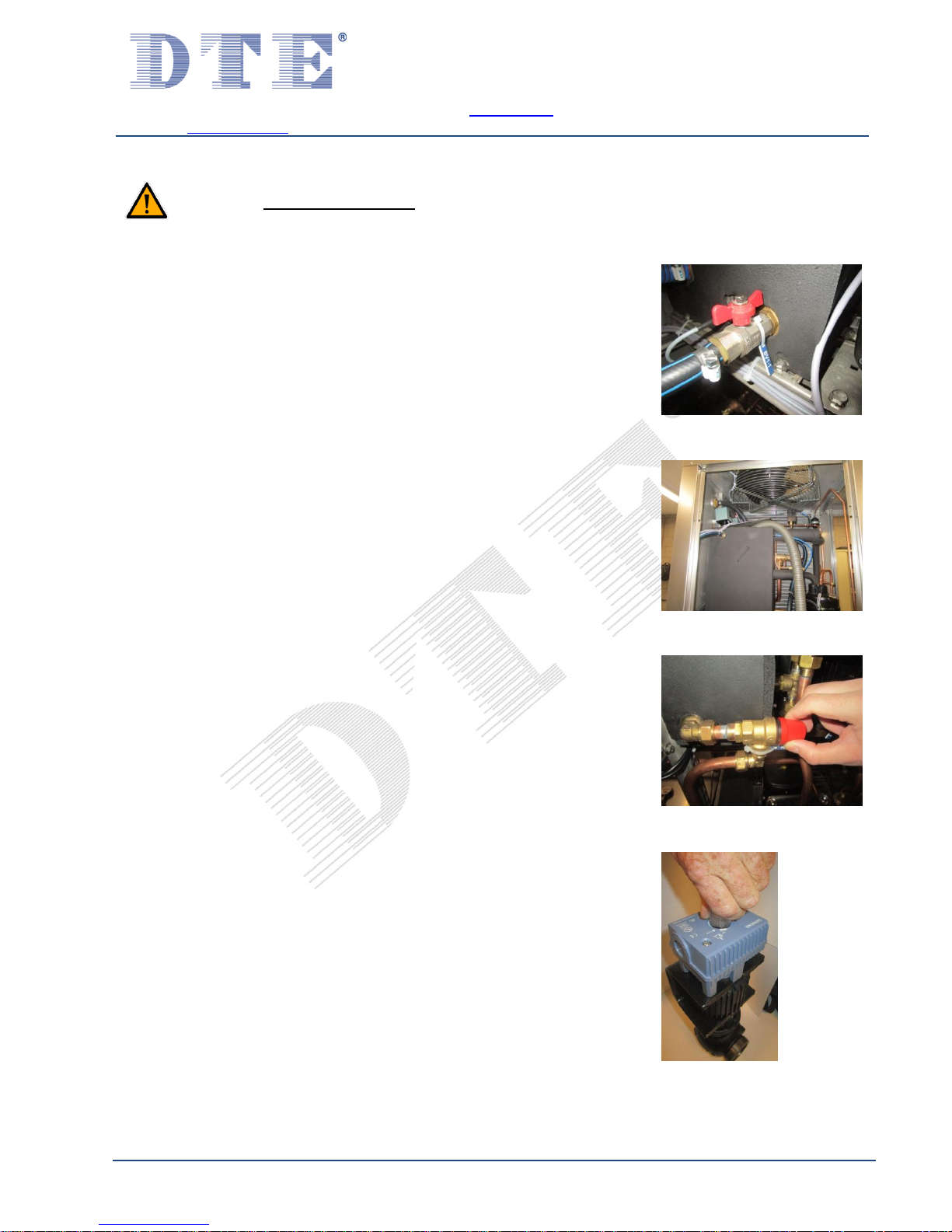
3.1.1 Draining water from the machine .............................................................................................................................................5
3.1.2 Packing, transport and storage instructions .............................................................................................................................7
3.2 Correct applications.......................................................................................................................................................................7
3.3 Application area ............................................................................................................................................................................7
4GENERAL DESCRIPTION .....................................................................................................................................................................8
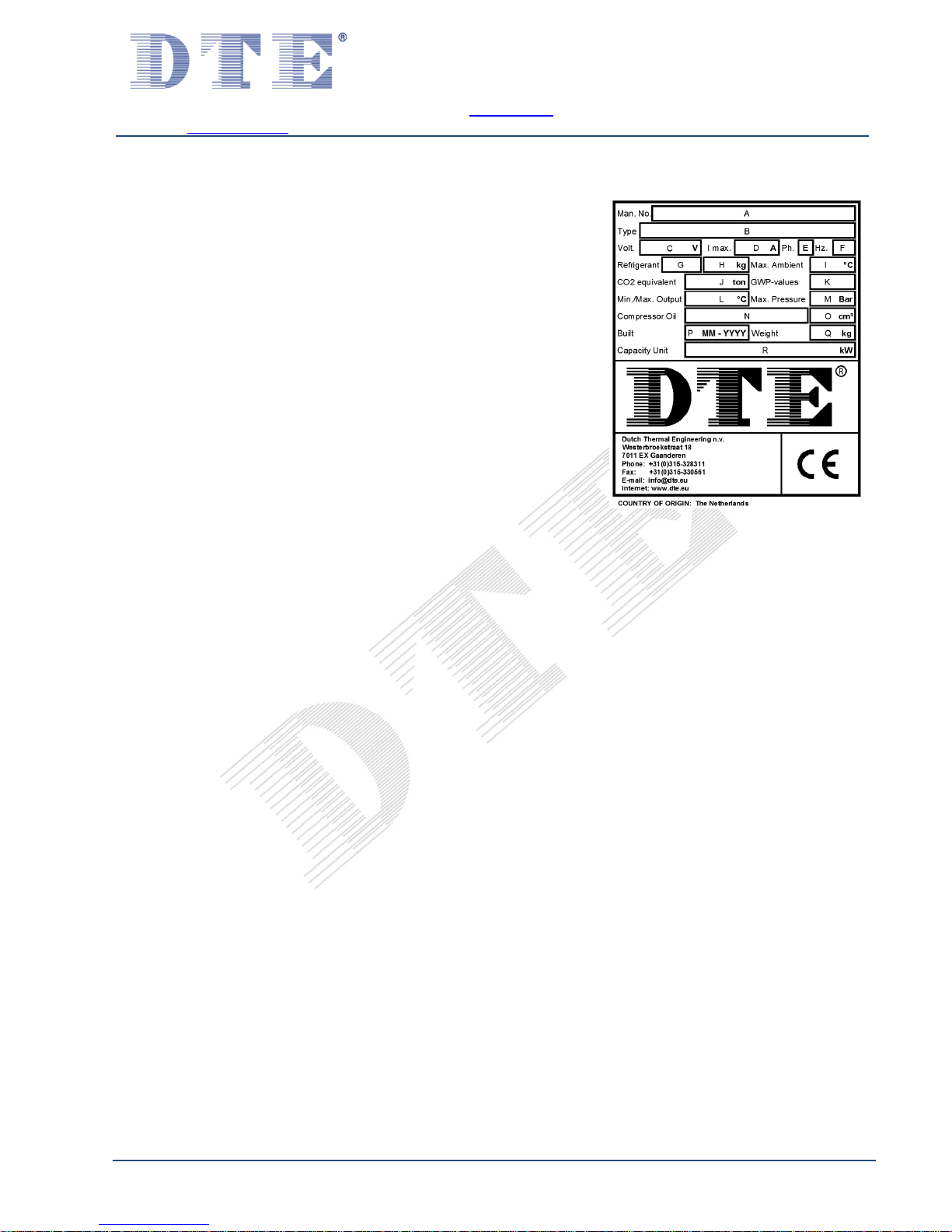
4.1 Identification..................................................................................................................................................................................9
5COMMISSIONING ............................................................................................................................................................................10
5.1 Connecting cooling water pipes...................................................................................................................................................11
5.2 Connecting overflow pipe ............................................................................................................................................................12
5.3 Connecting power supply............................................................................................................................................................. 12
5.3.1 Plug-in terminals .....................................................................................................................................................................13
5.4 Connecting external contacts ......................................................................................................................................................13
5.5 Water quality...............................................................................................................................................................................14
5.6 Filling of (external) pipes and systems CoolMaster (K) ................................................................................................................15
5.7 Filling of (external) pipes and systems CoolMaster (N)................................................................................................................ 16
5.8 Filling of the system CoolMaster (K) ............................................................................................................................................ 19
5.9 Filling of the system CoolMaster (N)............................................................................................................................................20
5.10 Deaerating...................................................................................................................................................................................21
5.11 Setting thermostat....................................................................................................................................................................... 22
5.12 Commissioning after long standstill ............................................................................................................................................23
6MEANING OF ALARMS (IF APPLICABLE) ...........................................................................................................................................24
7FAULT ANALYSIS..............................................................................................................................................................................25
8MINIMUM INSPECTION-INTERVAL SCHEME.....................................................................................................................................26
9CLEANING OF THE MACHINE............................................................................................................................................................27
10 CHECKS .......................................................................................................................................................................................27
11 SERVICE.......................................................................................................................................................................................27
12 GUARANTEE ................................................................................................................................................................................28
13 REMOVAL....................................................................................................................................................................................28
14 APPENDIX ...................................................................................................................................................................................29
14.1 Options ........................................................................................................................................................................................30
14.2 Connection diagram filling the system ........................................................................................................................................31
14.3 Watertreatment ..........................................................................................................................................................................32
14.4 Guidline for water quality in DTE installations............................................................................................................................. 33
14.5 User manual thermostat.............................................................................................................................................................. 34
14.6 Safety information sheets............................................................................................................................................................37
14.7 Comments....................................................................................................................................................................................45
14.8 Technical information.................................................................................................................................................................. 46
* Specification list ..................................................................................................................................................................................... 46
* Machine drawing ...................................................................................................................................................................................46
* Parts list .................................................................................................................................................................................................46
* Flow scheme ..........................................................................................................................................................................................46
* Electrical scheme....................................................................................................................................................................................46
* User manual thermostat........................................................................................................................................................................46
* Safety data sheet refrigerant.................................................................................................................................................................46
* Other...................................................................................................................................................................................................... 46
ENGLISH

T h e N e t h e r l a n d s
w w w . d t e . e u
Dutch Thermal Engineering n.v.
Westerbroekstraat 18
7011 EX Gaanderen
Phone : +31(0)315-328311
Specialist in:
Industrial ….Cooling
….Heating
….Tempering
….Heat Recovery
V00-08-2017 Page 2
1
1
D
Di
is
sc
cl
la
ai
im
me
er
r
The manufacturer reserves the right to change parts at any time to change, without prior or immediate notice to the customer. The contents of
this manual may also be changed without prior warning. This is an original manual, and is valid for the machine in its standard version. The
manufacturer can therefore not be held liable for any damages resulting from specifications that deviate from the standard version delivered to
you. For information on adjustments, maintenance and repair insofar as this guide does not provide it, please contact the technical department
of your supplier. This manual was drawn up with the greatest possible care, however the manufacturer cannot accept any liability for any errors
in this book or any consequences thereof. Finally, this manual is a personal and confidential communication to the user. No part of this
publication may be reproduced, copied, altered or transmitted in any form or in any manner whatsoever without written permission from Dutch
Thermal Engineering n.v.

T h e N e t h e r l a n d s
w w w . d t e . e u
Dutch Thermal Engineering n.v.
Westerbroekstraat 18
7011 EX Gaanderen
Phone : +31(0)315-328311
Specialist in:
Industrial ….Cooling
….Heating
….Tempering
….Heat Recovery
V00-08-2017 Page 3
2
2
E
EU
U-
-D
De
ec
cl
la
ar
ra
at
ti
io
on
n
o
of
f
c
co
on
nf
fo
or
rm
mi
it
ty
y
Manufacturer: D.T.E. n.v.
Address: Westerbroekstraat 18
7011 EX GAANDEREN / HOLLAND
Hereby certifies that:
The CoolMaster meets the requirements of the Machinery Directive
(Directive 2006/42/EC, as amended),
and the national legislation implementing this Directive;
Meets the provisions of the following other EU directives.
- 2014/35/EU Low Voltage Directive
- 2014/30/EU EMC directive
- 2014/68/EU Pressure Equipment Directive (PED)
And furthermore certifies that
The following (parts of) harmonised standards are applied:
- NEN-EN-IEC 60204-1:2006/C11:2010
- NEN-EN-ISO 12100:2010
- NEN-EN 378-2:2016
- NEN-EN-ISO 13857:2008
The following (parts of) national technical standards and specifications are used:
- Cooling Systems Leak Tightness Arrangement (Dutch abbreviation: RLK).
Person authorised to draw up technical documentation:
Mr T.J.H.M Ratering
(Manager Engineering)
Signed in Gaanderen on 09-12-2016
F.G.R. Geerdink
General Manager

T h e N e t h e r l a n d s
w w w . d t e . e u
Dutch Thermal Engineering n.v.
Westerbroekstraat 18
7011 EX Gaanderen
Phone : +31(0)315-328311
Specialist in:
Industrial ….Cooling
….Heating
….Tempering
….Heat Recovery
V00-08-2017 Page 4
3
3
S
Sa
af
fe
et
ty
y
i
in
ns
st
tr
ru
uc
ct
ti
io
on
ns
s
a
an
nd
d
w
wa
ar
rn
ni
in
ng
gs
s
Always observe the following safety instructions and warnings!
WARNING!
Warning of possible damage to the device, environment or user
WARNING!
Warning of electricity and / or current threat
WARNING!
Warning of possible entrapment hazard
Compliance with the technical manual is a prerequisite for fault-free operation and the honouring of any
warranty claims. Therefore please read the technical manual carefully before you start working with your
device! The manual must therefore be kept near the machine. The CoolMaster is under pressure with a
refrigerant, more information about this can be found in Appendix 14.6.
This user’s manual was written for types similar to DTE CoolMaster (K), (N) type machines. Therefore
certain topics may not apply to your machine. For the same reason, the images may differ slightly from
how your machine actually looks. When deviating from the standard, a machine drawing is included as
an attachment.

T h e N e t h e r l a n d s
w w w . d t e . e u
Dutch Thermal Engineering n.v.
Westerbroekstraat 18
7011 EX Gaanderen
Phone : +31(0)315-328311
Specialist in:
Industrial ….Cooling
….Heating
….Tempering
….Heat Recovery
V00-08-2017 Page 5
3
3.
.1
1
W
Wa
at
te
er
r
d
dr
ra
ai
in
ni
in
ng
g,
,
p
pa
ac
ck
ki
in
ng
g,
,
t
tr
ra
an
ns
sp
po
or
rt
t
a
an
nd
d
s
st
to
or
ra
ag
ge
e
i
in
ns
st
tr
ru
uc
ct
ti
io
on
ns
s
o
of
f
D
DT
TE
E
i
in
ns
st
ta
al
ll
la
at
ti
io
on
ns
s.
.
These actions are general and have to been carried out, of course, if applicable for the
application by qualified personal!
3
3.
.1
1.
.1
1
D
Dr
ra
ai
in
ni
in
ng
g
w
wa
at
te
er
r
f
fr
ro
om
m
t
th
he
e
m
ma
ac
ch
hi
in
ne
e
Step 1: Close the filling connection (D1)
Step 2: Drain the Water tank of the cooling system by opening the ball
valve. (See Figure 3.1) Further draining of the Water tank with a wet
vacuum cleaner. (See Figure 3.2)
Step 3: Drain the Tempering/Hot water tank by opening the
drainage/overflow valve. (See Figure 3.3)
Step 4: If present, switch on all solenoid valve by external power.
Step 5: If present, switch al 3 way-mix- regulation valve into the middle
position. (See Figure 3.4)
Figure 3.1
Figure 3.2
Figure 3.3
Figure 3.4

T h e N e t h e r l a n d s
w w w . d t e . e u
Dutch Thermal Engineering n.v.
Westerbroekstraat 18
7011 EX Gaanderen
Phone : +31(0)315-328311
Specialist in:
Industrial ….Cooling
….Heating
….Tempering
….Heat Recovery
V00-08-2017 Page 6
Step 6: Drain all connection on the machine with a wet vacuum
cleaner. (See Figure 3.5)
Step 7: Open all BVS valves if present (See flow diagram) and
remove the interior (See Figure 3.6). Drain the connection on the
outside of the machine with a wet vacuum cleaner. The interior will be
transported separately and has to be assembled before
commissioning.
Step 8: Remove all plugs of the water pumps. After this drain al pumps
with a wet vacuum cleaner. (See Figure 3.7 and Figure 3.8)
Figure 3.5
Figure 3.6
Figure 3.7
Figure 3.8

T h e N e t h e r l a n d s
w w w . d t e . e u
Dutch Thermal Engineering n.v.
Westerbroekstraat 18
7011 EX Gaanderen
Phone : +31(0)315-328311
Specialist in:
Industrial ….Cooling
….Heating
….Tempering
….Heat Recovery
V00-08-2017 Page 7
3
3.
.1
1.
.2
2
P
Pa
ac
ck
ki
in
ng
g,
,
t
tr
ra
an
ns
sp
po
or
rt
t
a
an
nd
d
s
st
to
or
ra
ag
ge
e
i
in
ns
st
tr
ru
uc
ct
ti
io
on
ns
s
Before packing, transport and storage, first follow the instructions of chapter 3.1.1 Draining water
from the machine.
Attention! Before transport the machine has to be protected with the also delivered cardboard
box or has to be wrapped with bubble wrap. The machine has to be transported and stored
perpendicular at all time on its fundament on the provided pallet!
The machine has to be placed perpendicular on its fundament at all time.
Attention! In no way the machine can be stacked or overturned. This during transport and storing
as well during repairs and commissioning. Even when the machine is not used it should be
perpendicular at all times.
Attention! Not following these instruction can cause big damage to the machine.
Use at all time the right equipment such as a pallet truck and a forklift truck.
3
3.
.2
2
C
Co
or
rr
re
ec
ct
t
a
ap
pp
pl
li
ic
ca
at
ti
io
on
ns
s
The CoolMaster (K)(N) may only be kept inside a cool, well-ventilated, frost-free building!
The minimum and maximum ambient temperature can be found in the relevant specifications list.
The CoolMaster (K) is only suitable for tap water of drinking quality.
The CoolMaster (N) is only suitable for tap water of drinking quality, mixing with appropriate antifreeze
(glycol) in suitable mixing ratio.
Information on the correct water-glycol ratio and the recommended type of glycol can be found on the
specification list corresponding to the machine.
Please consult the relevant specification list for information on the minimum and maximum
environmental temperature, the right water-glycol ratio and the recommended type of glycol.
Attention! In no way the machine can be stacked or overturned. This during transport and storing
as well during repairs and commissioning. Even when the machine is not used it should be
perpendicular at all times.
Attention! Not following these instruction can cause big damage to the machine.
3
3.
.3
3
A
Ap
pp
pl
li
ic
ca
at
ti
io
on
n
a
ar
re
ea
a
CAUTION! Application is prohibited:
- In explosive atmospheres.
- In environments with hazardous oils, acids, gases, fumes, substances, radiation, etc.
- Corrosive environment.

T h e N e t h e r l a n d s
w w w . d t e . e u
Dutch Thermal Engineering n.v.
Westerbroekstraat 18
7011 EX Gaanderen
Phone : +31(0)315-328311
Specialist in:
Industrial ….Cooling
….Heating
….Tempering
….Heat Recovery
V00-08-2017 Page 8
4
4
G
Ge
en
ne
er
ra
al
l
d
de
es
sc
cr
ri
ip
pt
ti
io
on
n
The CoolMaster is a complete plug and play water cooler with integrated water cooler tank, pump, condenser and
controls. Is built for perfect cooling in closed industrial process water systems.
A
=
Cooling water inlet, see specification list
B
=
Cooling water outlet, see specification list
C
=
Drain water tank, see specification list
D1
=
Filling water connection, see specification list
(not present in machines, specified as (N)(NF))
D2
=
Filling water facility
E
=
Overflow water tank, see specification list
F
=
Bushing coupling electrical supply cable
G
=
Control panel
H
=
Incoming condenser air
I
=
Removable cover
CAUTION! POSITION THE COVER(I) BEFORE SWITCHING ON THE
MACHINE!
J
=
Fixing bolts cover, 10 pieces
K
=
Air grille outgoing condenser air
L
=
Rubber legs, 4 pieces
P
=
Sight glass
Maximum glycol/water level
Minimum glycol/water level
S1
=
Main switch
* When deviating from the standard, a machine drawing is included as an attachment!
OFF
OFF
0
0
ON
1
S1
IJ
G
P
D2
C
F
FF
D1
A
B
E
I
H
L
K

T h e N e t h e r l a n d s
w w w . d t e . e u
Dutch Thermal Engineering n.v.
Westerbroekstraat 18
7011 EX Gaanderen
Phone : +31(0)315-328311
Specialist in:
Industrial ….Cooling
….Heating
….Tempering
….Heat Recovery
V00-08-2017 Page 9
4
4.
.1
1
I
Id
de
en
nt
ti
if
fi
ic
ca
at
ti
io
on
n
The identification plate is located on the left next to the fan. (Figure 4.1)
A
=
Machine number/ serial number
Figure 4.1
B
=
Machine type
C
=
Voltage
D
=
Maximum Current
E
=
Number of phases
F
=
Frequency in Hz.
G
=
Refrigerant type
H
=
Refrigerant mass
I
=
Maximum ambient temperature
J
=
CO2 equivalent
K
=
GWP-values
L
=
Thermostat Temperature range
M
=
Maximum pressure
N
=
Compressor lubrication
O
=
Compressor oil volume
P
=
Built
Q
=
Weight
R
=
Cooling capacity

T h e N e t h e r l a n d s
w w w . d t e . e u
Dutch Thermal Engineering n.v.
Westerbroekstraat 18
7011 EX Gaanderen
Phone : +31(0)315-328311
Specialist in:
Industrial ….Cooling
….Heating
….Tempering
….Heat Recovery
V00-08-2017 Page 10
5
5
C
Co
om
mm
mi
is
ss
si
io
on
ni
in
ng
g
See for the connections chapter 4.
CAUTION! The installation work must be carried out by a certified professional!
Place the CoolMaster at a level position and at least 1 meter from a wall. For a good functioning of the
CoolMaster we recommend keeping the distance between the CoolMaster and the user to a minimum.
The cooling water pipes between the CoolMaster and the user must be longer than 15 meters.
WARNING! The diameter of the pipes/hoses must at least match with the connections on the
CoolMaster.
The hoses MUST be reinforced with braided fibre to prevent kinking the hose.

T h e N e t h e r l a n d s
w w w . d t e . e u
Dutch Thermal Engineering n.v.
Westerbroekstraat 18
7011 EX Gaanderen
Phone : +31(0)315-328311
Specialist in:
Industrial ….Cooling
….Heating
….Tempering
….Heat Recovery
V00-08-2017 Page 11
5
5.
.1
1
C
Co
on
nn
ne
ec
ct
ti
in
ng
g
c
co
oo
ol
li
in
ng
g
w
wa
at
te
er
r
p
pi
ip
pe
es
s
1
1
Let op! Before making any connections to the CoolMaster,
clean the external pipes. Dirt must be prevented from
entering the CoolMaster. It may cause serious damage to
the system and the CoolMaster.
Connect the following pipes:
- A and B: cooling water pipes between CoolMaster and the
User.
- D1: If you wish to fill automatically.
(does not apply to machinery specified as (N))
Step 1:
1. Install the ball valve (BVS-1) on the cooling water inlet (A)
2. Install cooling water pipe between CoolMaster (BVS-1) and
User. (See Figure 5.1)
The ball valve (BVS-1) must be kept closed, unless otherwise
indicated!
Step 2:
1. Install the ball valve (BVS-2) on the cooling water outlet (B).
2. Install the ball valve (BVS-3) on the T-piece (central section).
3. Install the cooling water pipe between CoolMaster
(on the T-piece) and the user. (See Figure 5.2)
The ball valves (BVS-2 and BVS-3) must be kept closed, unless
otherwise indicated!
Step 3:
1. Connect the cooling water pipes between CoolMaster and
user. (BVS-1 and BVS-3), See appendix §14.2
2. Connect D1 to a water tap if you wish to fill
automatically.
(does not apply to machinery specified as (N))
Figure 5.1
Figure 5.2
1Ball valves are not supplied as standard.
Available by DTE with art. no. 87000090

T h e N e t h e r l a n d s
w w w . d t e . e u
Dutch Thermal Engineering n.v.
Westerbroekstraat 18
7011 EX Gaanderen
Phone : +31(0)315-328311
Specialist in:
Industrial ….Cooling
….Heating
….Tempering
….Heat Recovery
V00-08-2017 Page 12
5
5.
.2
2
C
Co
on
nn
ne
ec
ct
ti
in
ng
g
o
ov
ve
er
rf
fl
lo
ow
w
p
pi
ip
pe
e
Connect the overflow pipe (E). To enable good outflow of superfluous water, the overflow pipe must be
able to flow out into the open sewer without any foreseeable obstructions. The length of the overflow
pipe should be kept to a minimum. The pipe should also flow downwards, from the perspective of the
CoolMaster (E).
CAUTION! For machines filled with a mixture of water and glycol (machines displaying (N)), the
excess mixture from connection (E) must not be discharged into public sewers for reasons
relating to environmental law.
5
5.
.3
3
C
Co
on
nn
ne
ec
ct
ti
in
ng
g
p
po
ow
we
er
r
s
su
up
pp
pl
ly
y
Attention! Work may only be carried out on the electrical installation of the CoolMaster by an
authorised, professionally competent person.
Attention! The CoolMaster must only be connected to a clockwise rotary field.
Turn off the main switch on the control panel (G).
Connect your electrical power supply cable to the appropriate terminals in the control box via the cable
entry (F). Refer to the electro-technical diagram for the connection of the cable cores. Consult the
diagram number as stated on the technical specifications sheet corresponding to the serial number of
the CoolMaster.
Consult the type plate for the correct voltage.
Attention! Ensure the voltage as stated on the type plate is also the voltage on each phase wire.
Of no less importance is the mains frequency (50 or 60 Hz) corresponding to the frequency on the type
plate. The maximum voltage deviation is +6% and –10% from the voltage indicated on the type plate.

T h e N e t h e r l a n d s
w w w . d t e . e u
Dutch Thermal Engineering n.v.
Westerbroekstraat 18
7011 EX Gaanderen
Phone : +31(0)315-328311
Specialist in:
Industrial ….Cooling
….Heating
….Tempering
….Heat Recovery
V00-08-2017 Page 13
5
5.
.3
3.
.1
1
P
Pl
lu
ug
g-
-i
in
n
t
te
er
rm
mi
in
na
al
ls
s
Use a screwdriver with a 3mm wide point. Push the screwdriver
in the square recess to open the spring. (See Figure 5.3)
Figure 5.3
Place the 10mm stripped wire with cable end into the round
recess and press the wire into the terminal as deeply as
possible. (See Figure 5.4)
Figure 5.4
Remove the screwdriver. Check whether the wire is firmly
connected. (See Figure 5.5)
Figure 5.5
5
5.
.4
4
C
Co
on
nn
ne
ec
ct
ti
in
ng
g
e
ex
xt
te
er
rn
na
al
l
c
co
on
nt
ta
ac
ct
ts
s
Also connect the electrical cables for the external contact(s).
See for supplied wiring diagram.

T h e N e t h e r l a n d s
w w w . d t e . e u
Dutch Thermal Engineering n.v.
Westerbroekstraat 18
7011 EX Gaanderen
Phone : +31(0)315-328311
Specialist in:
Industrial ….Cooling
….Heating
….Tempering
….Heat Recovery
V00-08-2017 Page 14
5
5.
.5
5
W
Wa
at
te
er
r
q
qu
ua
al
li
it
ty
y
CAUTION! The CoolMaster is not suitable for use with demineralized water or water containing
high levels of minerals or iron.
The filling water which is used must be of good quality. It must at least be of drinking water quality and
the water must not contain high levels of lime and/or iron, as it may cause serious damage.
You must check the water regularly.
The minimum filling pressure must be 2,5 bar.
See Appendix 14.3 for extra information.
See Appendix 14.4 for directive water quality.
CAUTION! The CoolMaster (N) are only suitable for tap water of drinking water quality mixed with
the correct ratio of a suitable anti-freeze (glycol).

T h e N e t h e r l a n d s
w w w . d t e . e u
Dutch Thermal Engineering n.v.
Westerbroekstraat 18
7011 EX Gaanderen
Phone : +31(0)315-328311
Specialist in:
Industrial ….Cooling
….Heating
….Tempering
….Heat Recovery
V00-08-2017 Page 15
5
5.
.6
6
F
Fi
il
ll
li
in
ng
g
o
of
f
(
(e
ex
xt
te
er
rn
na
al
l)
)
p
pi
ip
pe
es
s
a
an
nd
d
s
sy
ys
st
te
em
ms
s
C
Co
oo
ol
lM
Ma
as
st
te
er
r
(
(K
K)
)
Step 1:
1. All the connections must be made in accordance with §5.1
2. Turn the air vent(s) in your system to “open”. (The venting
must take place at the highest point(s) in pipe(s))
CAUTION! Do not use automatic air vents!
CAUTION! CoolMaster (N) filling procedure in §5.9
3. Connecting the filling water (min. 2.5 Bar) to BVS-3.
4. Turn the valve (BVS-3) to “open”. (See Figure 5.6)
Step 2:
Excess air will be released from the pipe(s) though the air
release valve(s).
If the water spills from the air release valve(s), the external
pipes/systems are filled with water.
1. Turn the ball valve (BVS-3) to “closed”. (See Figure 5.7)
2. Turn the air release valve(s) in your system to the
"closed" position.
3. Turn the water fill line to “closed”.
4. Remove the fill water line which is mounted on BVS-3.
Step 3:
1. Turn the ball valve (BVS-1) to “open”. (See Figure 5.8)
2. Turn the ball valve (BVS-2) to “open”. (See Figure 5.9)
When these steps have been completed correctly, the entire
system will be filled with water.
Figure 5.6
Figure 5.7
Figure 5.8
Figure 5.9

T h e N e t h e r l a n d s
w w w . d t e . e u
Dutch Thermal Engineering n.v.
Westerbroekstraat 18
7011 EX Gaanderen
Phone : +31(0)315-328311
Specialist in:
Industrial ….Cooling
….Heating
….Tempering
….Heat Recovery
V00-08-2017 Page 16
5
5.
.7
7
F
Fi
il
ll
li
in
ng
g
o
of
f
(
(e
ex
xt
te
er
rn
na
al
l)
)
p
pi
ip
pe
es
s
a
an
nd
d
s
sy
ys
st
te
em
ms
s
C
Co
oo
ol
lM
Ma
as
st
te
er
r
(
(N
N)
)
Step 1:
1. The connections must be made in accordance with §5.1.
The ball valve (BVS-1) must be kept closed, unless otherwise
indicated! (See Figure 5.10)
CoolMaster (N)
Filling set for mixture of water and glycol2
Step 2:
See Figure 5.11 and Figure 5.12. for a complete image from
the filling set. The mixture of water and glycol will be provided
in the supplied tank.
The ratio of the mixture is indicated in the relevant specification
list.
Figure 5.10
Figure 5.11
Figure 5.12
Figure 5.13
2The fillingset is not supplied as standard.
Available by DTE with art. no. 87000089

T h e N e t h e r l a n d s
w w w . d t e . e u
Dutch Thermal Engineering n.v.
Westerbroekstraat 18
7011 EX Gaanderen
Phone : +31(0)315-328311
Specialist in:
Industrial ….Cooling
….Heating
….Tempering
….Heat Recovery
V00-08-2017 Page 17
1. Install the cooling water pipe between CoolMaster
(on the T-piece) and the user.
The ball valve (BVS-2 and BVS-3) must be kept closed, unless
otherwise indicated! (See Figure 5.13)
2. Install the link (BVS-5) onto the ball valve (BVS-3) (Minimum
pressure 2.5 bar). (See Figure 5.14)
Step 3:
1. Turn the air release valve(s) to “open”. (It is essential
that the air release(s) takes place at the highest
point(s) in the pipe(s))
CAUTION! Do not use automatic air release valves!
2. Turn the ball valve (BVS-5) to “open”.
(See Figure 5.15)
3. Turn the ball valve (BVS-3) to “open”.
(See Figure 5.16 and Figure 5.17)
Figure 5.14
Figure 5.15
Figure 5.16
Figure 5.17

T h e N e t h e r l a n d s
w w w . d t e . e u
Dutch Thermal Engineering n.v.
Westerbroekstraat 18
7011 EX Gaanderen
Phone : +31(0)315-328311
Specialist in:
Industrial ….Cooling
….Heating
….Tempering
….Heat Recovery
V00-08-2017 Page 18
Step 4:
Excess air will be released from the pipe(s) though the air
release valve(s).
If the water and glycol mixture spills from the air release
valve(s), the external pipes/systems are filled with the water
and glycol mix.
1. Turn the ball valve (BVS-3) to “closed” (See Figure 5.18)
2. Turn the air release valve(s) in your system to the
"closed" position.
3. Turn the ball valve (BVS-5) to “closed”:
4. Remove the ball valve (BVS-5) (See Figure 5.19)
Step 5:
1. Turn the ball valve (BVS-1) to “open” (See Figure 5.20)
2. Turn the ball valve (BVS-2) to “open” (See Figure 5.21)
When these steps have been completed correctly, the entire
system will be filled with the water and glycol mixture.
Figure 5.18
Figure 5.19
Figure 5.20
Figure 5.21

T h e N e t h e r l a n d s
w w w . d t e . e u
Dutch Thermal Engineering n.v.
Westerbroekstraat 18
7011 EX Gaanderen
Phone : +31(0)315-328311
Specialist in:
Industrial ….Cooling
….Heating
….Tempering
….Heat Recovery
V00-08-2017 Page 19
5
5.
.8
8
F
Fi
il
ll
li
in
ng
g
o
of
f
t
th
he
e
s
sy
ys
st
te
em
m
C
Co
oo
ol
lM
Ma
as
st
te
er
r
(
(K
K)
)
Fill the CoolMaster with water (fill automatically or manually):
1. Auto fill (D1) (a power supply is required; a minimum filling
pressure of 2.5 bar is required). (See Figure 5.22)
2. Manual fill (D2). (See Figure 5.23)
External systems must be filled via an external filling point.
See chapter §5.6 for instructions.
WARNING! To add any chemicals or other substances,
please consult the supplier.
Figure 5.22
Figure 5.23
Table of contents
Popular Accessories manuals by other brands

Mianyang Weibo Electronic
Mianyang Weibo Electronic WBI414N21 user manual

Omron
Omron FZ3 Series user manual

Flexco
Flexco MHCP Precleaner Installation, operation and maintenance manual

Panasonic
Panasonic MIR-H163-PA Service manual

Commercial Electric
Commercial Electric 5310-WH installation guide

Chauvet
Chauvet COLORstrip LED-FS1 user manual