WATER QUALITY
Your RADIANT water heater has been manufactured to suit water conditions of most
Australian metropolitan supplies. Please note that harsh water supplies can have a
detrimental effect on the water heater and its life expectancy. If you are unsure about your
water quality you can obtain information from your local water supply authority.
The water heater is designed for use in areas where the Total Dissolved Solids (TDS)
content of the water supply is less than 2500 mg/L.
In areas where the TDS exceeds 600mg/L it is possible that the magnesium alloy anode
(supplied in the heater) may become over reactive. To alleviate this, the magnesium alloy
anode should be replaced with an aluminium alloy anode, available from your local Dux
supplier, by removing the seven (7) screws in the case top to gain access to the anode
socket.
Water can also be very corrosive, the measure of this is the saturation index, if the water
saturation index is greater than 0.40 a expansion control valve should be fitted and where
the index is greater than 0.80 an aluminium anode should be fitted. Please consult our
Service Department for advise if required.
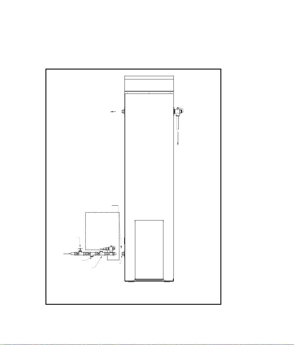
TESTING THE WATER HEATER
Test operation by lighting the water heater (see Operating Instructions). Check that the
test point pressure of water heater complies with the Data Plate. Check burner aeration
and check that the pilot flame plays on the last 4mm of the thermocouple. If necessary,
adjust accordingly by following the instructions under “Adjustments” in the Service
Instructions.
Note: Instruct owner in water heater operation before leaving.
The appliance is not intended for use by young children or infirm persons without
supervision. Young children should be supervised to ensure that they do not play
with the appliance.
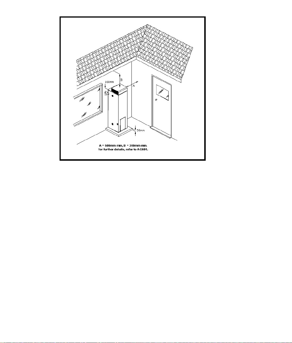
WARNING!
It is essential for the safe operation of this gas heater that clothing or any other flammable
material should not be placed against or on top of the water heater. In addition, do not
store flammable or corrosive materials, such as dry cleaning fluids, pool chemicals, etc., in
close proximity to the heater.
The use of aerosol sprays in the vicinity of the heater should be avoided. The propellant
gases used in these devices, e.g. fly-spray, hair-spray and laundry aids, can breakdown in
the flames of the burner and produce corrosive agents.
8


 null")
 null")


 Operation and maintenance instructions")