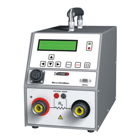
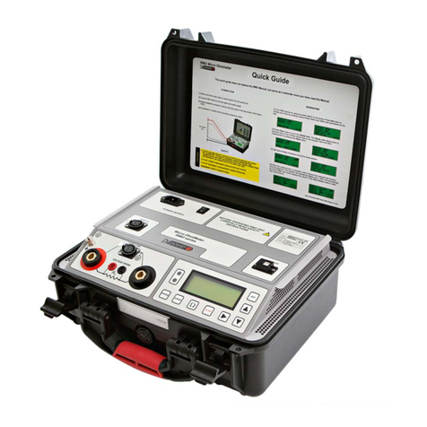
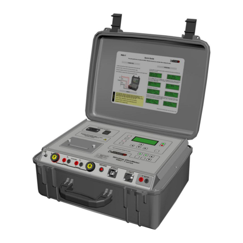
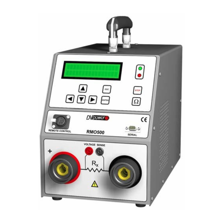
DV Power RMO-H User manual

Micro ohmmeter RMO-H
Handheld Micro Ohmmeter RMO-H
Manual
Manual Version: M-RH00NN-300-EN
This Manual refers to the firmware version 1.0x
Publishing date: 2018-01-10

Manual RMO-H
M-RH00NN-300-EN 2
Contents
1Introduction …………………………………………………………………………………………………...3
1.1 Safety Instructions.....................................................................................................................3
1.2 Intended Use.............................................................................................................................5
2Description …………………………………………………………………………………………………….6
2.1 Front Panel Components...........................................................................................................7
3. Getting Started.................................................................................................................................8
3.1 Connecting RMO-H to Test Object ............................................................................................8
3.2 Connecting RMO-H to Circuit Breaker.......................................................................................9
3.3 Connecting RMO-H to Both Sides Grounded (BSG) Circuit Breaker .......................................11
3.4 Settings...................................................................................................................................12
3.5 Measuring with RMO-H ...........................................................................................................14
3.6 Measurement parameters........................................................................................................16
4Error Messages..............................................................................................................................16
4.1 Error Message "SD Card Initiation Failed"...............................................................................16
4.2 Error Message "Connection VS"..............................................................................................16
4.3 Error Message "Open Connection"..........................................................................................17
5Troubleshooting .............................................................................................................................18
5.1 Measurement Accuracy Check................................................................................................18
5.2 Battery check...........................................................................................................................18
6Customer Service...........................................................................................................................19
7Packing the Instrument for Shipment..............................................................................................20
8Technical Data...............................................................................................................................21
9Instrument & Accessories...............................................................................................................23
Manufacturer Contact Information..........................................................................................................24

Manual RMO-H
M-RH00NN-300-EN 3
1 Introduction
This Manual provides instructions on how to use the RMO-H instruments safely, properly and efficiently.
The following instructions will help the user avoid unsafe situations, reduce maintenance costs and will
ensure the reliability and durability of the RMO-H instruments.
The RMO-H must be used in accordance with all existing safety requirements and regulations based on
national/local standards for accident prevention and environmental protection. In addition, the relevant
international standards are listed in the “Technical Data” paragraph section of this document.
1.1 Safety Instructions
Safety is the responsibility of the user. Before operating the RMO-H, please read the following safety
instructions carefully.
It is not recommended the RMO-H being used (or even turned on) without careful observation of the
instructions listed in this Manual. The RMO-H should only be operated by trained and authorized
personnel.
1.1.1 Safety Terms and Symbols
Terms in this Manual
These terms may appear in the Manual:
WARNING: Warning statements identify conditions or practices that could result in an injury or a loss
of life.
CAUTION: Caution statements identify conditions or practices that could result in damage to this
product or to the other property.
Terms on the Device
The following warning terms used in this document may appear on the device:
WARNING: indicates that a potential hazard may occur.
CAUTION: indicates that a potential damage may occur to the instrument or to the test object
connected to the instrument.
Symbols on the Device
The following symbols may appear on the device:
Refer to Manual
Protective Earth Terminal

Manual RMO-H
M-RH00NN-300-EN 4
1.1.2 Terms of Use
•The RMO-H shall be used only if it is in a good technical condition. Its use shall be in accordance
with local safety and industrial regulations. Adequate precautions must be taken to avoid any risks
related to high voltages associated with this equipment and nearby objects.
•The RMO-H shall be used only for the application purposes described in the ”Intended Use” section.
The manufacturer and distributors are not liable for a damage resulting from the wrong usage. The
user bears responsibility for not following the instructions defined in this document.
•Do not remove the protective casing of the RMO-H.
•All service and maintenance work must be performed by qualified personnel only.
1.1.3 Orderly Practices and Procedures
•The Manual shall always be available on the site where the RMO-H is used.
•Before using the RMO-H, all personnel (even personnel who only occasionally, or less frequently,
work with the RMO-H) assigned to operate the RMO-H should read the operations Manual.
•Do not make any modifications, extensions, or adaptations to the RMO-H.
•Use the RMO-H only with the original accessories provided by the manufacturer.
•Use the RMO-H and its original accessories for the device’s intended use only.
1.1.4 Device maintenance
Device should be kept in a clean condition to prevent excessive dust or other contaminants affecting
its operation. It should be cleaned with water/isopropyl alcohol after noticing any dirt/contaminants
on its surfaces.
1.1.5 Operator Qualifications
•Testing with the RMO-H should only be carried out by authorized and qualified personnel.
•While receiving training, instruction or education on the RMO-H device personnel should remain
under the constant supervision of an experienced operator while working with the test set and the
test object.
1.1.6 Safe Operating Procedures
•Before putting the RMO-H into operation, check the test set for any visible damage.
•Do not operate the RMO-H under wet or moist conditions (condensation).
•Do not operate the RMO-H if explosive gas or vapors are present.
•Only the external devices which meet the requirements for SELV equipment according to EN 60950
or IEC 60950 should be connected to the RMO-H through the serial interface.
•Removing the RMO-H protective casing will void the warranty. Any work inside the instrument
without prior authorization from DV Power will also void the warranty.
•If the RMO-H seems to be malfunctioning, please contact the DV Power Support Team (refer to the
“Manufacturer Contact Information” section) after previously checking the “Error Messages” section.
Manual RMO-H
M-RH00NN-300-EN 5
•Do not use the RMO-H without the extra protective ground cables supplied with the RMO-H. It must
never be operated in a non-grounded configuration as this may result in an electrical shock to the
user or damage the RMO-H. Always establish this connection first before establishing any other
connections and remove this connection as the very last one.
1.2 Intended Use
The Micro Ohmmeter RMO-H is a portable, handheld device designed for measuring contact resistances
of non-inductive test objects used in the electric power industry or similar branches.
It is employed for resistance measurement during manufacturing, commissioning and testing of:
•High, middle and low voltage circuit breakers,
•High, middle and low voltage disconnecting switches,
•High-current bus bar joints,
•Cable splices,
•Welding joints,
•Groundings.
CAUTION: Any use of the RMO-H other than mentioned above is being
considered improper and will void the warranty and exempt the
manufacturer from its liability for repair or exchange.
.

Manual RMO-H
M-RH00NN-300-EN 6
2 Description
RMO-H is a handheld Micro Ohmmeter based on a state of the art technology, using the most advanced
battery and switch mode technique available today. RMO-H is the battery supplied device, independent
from the mains power supply.
The high-capacity Li-Po battery enables generating a true DC ripple-free current up to 300 A. The test
current is user selectable and generated in an automatic regulated test ramp. By sloping the current up
and down, magnetic transients are virtually eliminated.
The RMO-H instrument can store internally up to 1000 measurements. The results are saved on the
micro SD card. All measurements are time and date stamped.
DV-Win software enables download and analysis of the results, creating and exporting test reports in
different formats, as well as full control of the test device. Communication between the RMO-H and a PC
is through a Bluetooth connection.
The set is equipped with the thermal and overcurrent protection. The RMO-H has a very high ability to
cancel electrostatic and electro-magnetic interference in HV electric fields. This is achieved by very
efficient filtration utilizing a proprietary hardware and software.
Figure 2-1:
Automatically
regulated test
current ramp

Manual RMO-H
M-RH00NN-300-EN 7
2.1 Front Panel Components
1 –LCD Display
TFT LCD 2.8 in (43,2 mm x 57,6 mm / 1.8 in x 2.3 in)
4 –Current output terminal (–)
2 –Keyboard
Used to control the device
5 –Protective Earth Connector
Used for protection against parasitic currents or voltages
3 –Current output terminal (+)
6 –Charger Connector
7 –Connectors for the voltage sense cables
(+) Standard banana connector (red)
(–) Standard banana connector (black)
8 - Remote control connector
1
Figure 2-2:
Front panel components
Figure 2-3:
Voltage sense and remote
control connectors
2
3
4
5
6
7
8

Manual RMO-H
M-RH00NN-300-EN 8
CAUTION: For protection against parasitic currents or voltages, always connect the
RMO-H protective earth connector to the protective earth (PE).
Please use only the manufacturer provided cable.
For safety reasons, always establish the protective earth connection before
establishing any other connection, and remove this connection as the very last step.
Voltage terminals
Voltage sense cable terminal –connecting the voltage sense test cable.
Charger Connector
The connector for charging the internal battery.
Operator Control
2.8 inches color touch-screen display
Displays the settings as well as the measured values during and after a test operation.
Keyboard
3. Getting Started
3.1 Connecting RMO-H to Test Object
NOTE: Cables should be connected and removed to/from RMO-H device ONLY
when the RMO-H is switched off.
CAUTION: Always connect the measuring cables to the RMO-H first and then to the
test object; and when disconnecting, always disconnect the cables from the test
object first and after that from the RMO-H. The grounding wire PE should be
disconnected last. Failure to do this may result in a serious injury or even a loss of
life.
Use this button to turn on/off the device.
Use the Ωbutton to start the test.
Use the ENTER button to confirm the defined
test parameters, language, time, date and
limits.
Use the UP/DOWN buttons to navigate
through active menu.
Use the MEM button to go to Memory Menu.
Use the SET button to go to Settings Menu.
Figure 2-4:
Keyboard

Manual RMO-H
M-RH00NN-300-EN 9
To maximize accuracy and measurement repeatability make sure that all clamps have a good
connection to the test object and avoid any connection between Sense and Current clamps.
In case that combined current and sense cables are provided with the RMO-H device, the user only
needs to connect the TTA clamps to the connection points. The resistance between these points will be
measured by the device.
3.2 Connecting RMO-H to Circuit Breaker
Before connecting the RMO-H to a circuit breaker make sure that:
the breaker is disconnected or separated from its circuit on both sides of the breaker in
accordance with the national safety regulations; always comply with local safety regulations
when using the RMO-H,
the breaker is properly grounded to a protective earth (PE),
the RMO-H itself is properly grounded. To do so, connect the grounding screw of the RMO-H to a
PE using only the manufacturer provided grounding cable.
When testing high-voltage circuit breakers with RMO-H, a different cable’s length could be used. The
short cable (red cable, 1,3 m) connects the RMO-H to the CB’s bushing which is closer to the test person
and the device, while long cable (black cable, 3 or 5 m) is connected to the distant bushing on the other
side of the breaking point.
The connection diagram to a one-side grounded circuit breaker is illustrated in the figure below:
With RMO-H turned off, connect RMO-H
to the test object (Rt) in such a way that
the measuring cables from the "Voltage
Sense" input sockets are attached as
close as possible to the test object RX, and
closer to Rtthan the connection points of
the current feeding cables. That way,
resistance of both, cables and clamps is
almost completely excluded from the
resistance measurement.
Please pay attention to the polarity
while connecting the measuring
cables, otherwise the measurement
results will be incorrect.
Figure 3-1:
Connecting a test
object to RMO-H

Manual RMO-H
M-RH00NN-300-EN 10
1. Short test leads (current and voltage sense cables labeled with red color)
2. Longer test lead (current and voltage sense cables labeled with black color)
When testing MV Circuit Breakers, it is convenient to use Current and Sense cables with Kelvin probes.
Figure 3-2:
Connecting RMO-H
to a high-voltage
circuit breaker
Figure 3-3:
Connecting RMO-H to
circuit breaker using
cables with Kelvin
probes

Manual RMO-H
M-RH00NN-300-EN 11
3.3 Connecting RMO-H to Both Sides Grounded (BSG) Circuit Breaker
The RMO-H device provides a safer measurement approach to the breakers with both terminals
grounded. The connection method for both sides grounded circuit breakers is the same as for one side
grounded circuit breakers. This type of a measurement could provide less accurate results comparing to
a traditional one side grounding measurement, because of a small amount of current that can flow
through groundings. The inaccuracy depends of the resistance of the grounding loop. The measured
resistance of the circuit breaker mains contacts can be corrected if the resistance of the grounding loop
is known (or measured). The procedure is described in Application Note originally published by DV
Power (IBEKO Power AB) in Year 2011: “Main contact resistance measurement of a Circuit breaker with
both sides grounded (BSG)”.
The connection diagrams of the RMO-H device applied to both sides grounded circuit breaker is
presented in the following figure.
1. Short test leads (current and voltage sense cables labeled with red color)
2. Longer test lead (current and voltage sense cables labeled with black color)
3. Ground cable
4. Ground cable (used in case of Both Sides Grounded testing)
NOTE: The connection diagram for measurement in Both Sides Grounded
conditions is the same as for one side grounded circuit breaker.
Figure 3-4:
Connecting RMO-H
to both sides
grounded CB

Manual RMO-H
M-RH00NN-300-EN 12
3.4 Settings
If the RMO-H device is turned ON for the first time, or some additional system settings are required,
pressing the SET button will invoke the Settings menu, as illustrated below.
In the Settings menu Memory, Limits, Time & Date, Language parameters can be modified. In addition,
the Bluetooth option can be enabled/disabled. The UP and DOWN buttons are used for navigation and
the ENTER button for entering the selected submenu.
Setting Memory
To set default memory location on RMO-H, please use ENTER button to activate the Memory menu. In
the Memory menu, use UP and DOWN buttons to change values (status) in the selected fields.
ENTER button is used to confirm and SET button to cancel selected values (status).
Setting Rmax
To set RMO-H’s Rmax value, please use the RIGHT button, and then ENTER button to select the Set
Rmax menu.
Figure 3-5:
The Settings Menu
Figure 3-6:
The Memory screen

Manual RMO-H
M-RH00NN-300-EN 13
In the Rmax menu, define the status of Rmax (On or Off) and the assigned value of resistance.
Using UP/DOWN buttons select Off (Figure 3-7) or On option in order to DISABLE/ENABLE Rmax
function. Press ENTER to confirm and change cursor on Rmax value field.
Using UP/DOWN buttons in Rmax value field select a desired value between 1 µΩ and 1999 µΩ. The
default value is 100 µΩ. When the device is turned off and then turned on, the RMO-H remembers the
last saved setting of an Rmax value and a status.
Once these parameters are defined, press ENTER to return to the Settings menu.
Setting Time & Date
To set RMO-H’s date and time, please use the UP/DOWN buttons, and then ENTER button to select the
Time & Date menu.
Change the values in the selected fields with the UP/DOWN buttons and use ENTER button to confirm set
values.
One of three different date formats can be selected:
1. YY-MM-DD
2. DD-MM-YY
3. MM-DD-YY
Pressing ENTER to confirm, returns you to the Settings menu.
Pressing SET to cancel, returns also to the Settings menu, but without saved Time & Date settings.
Figure 3-8:
The Time & Date
screen
Figure 3-7:
The Rmax screen

Manual RMO-H
M-RH00NN-300-EN 14
Setting Language
To set RMO-H’s language, please use the UP/DOWN buttons, and then ENTER button to select the Set
Language menu.
If the user is satisfied with the values, all the selections can be confirmed by pressing ENTER.
Setting Bluetooth (ON/OFF)
To activate the Bluetooth option, press the ENTER button when the “Bluetooth” field is selected. When
Bluetooth is activated, the screen looks like in the figure below (green colored status):
3.5 Measuring with RMO-H
The start screen for setting the measurement parameters is presented in the figure below:
User can set the test current by using UP/DOWN buttons. No additional setting is needed for starting the
test. The measurement can start by pressing the Ω button or with the trigger button on the Kelvin probes.
Figure 3-9:
The Language screen
Figure 3-11:
Setting the test current in
start screen
Figure 3-10:
The Bluetooth
activation

Manual RMO-H
M-RH00NN-300-EN 15
Once a test is finished, the RMO-H automatically changes to the Result menu to display the test results.
The Result menu provides the result memory location, measured resistance value, measured test
current and voltage, as well as the parameters set for the test (set test current).
3.5.1 Test Results with Rmax Function Enabled
If the Rmax menu is set to option ON, once the test is finished, RMO-H automatically changes to the
Rmax to display the test results. In case the measured resistance is equal to or greater than maximum
assigned value, the result will be displayed in “red” color, as presented in the figure below:
In case the measured resistance is lower than set Rmax value the result will be displayed in “green” color,
as presented in the figure below:
The default value for Rmax is 100 µΩ. When the device is turned off and then turned
on, the RMO-H remembers the last saved setting of an Rmax value and a status.
Figure 3-13:
The Rmax showing
the test results
Figure 3-12:
The Result menu
showing the test results
obtained in Single test
Test current reached
Memory position that holds the results
Measured resistance
of test object
Figure 3-14:
The Rmax showing
the test results
Test current set
Measured voltage drop
at test object
101.4 µΩ
101.4 µΩ

Manual RMO-H
M-RH00NN-300-EN 16
3.6 Measurement parameters
The table below provides RMO-H device accuracy parameters under the maximal test current per the
range being used.
Table 3-1 Measurement parameters for RMO-H
Range
Recommended
Test Current
Nominal
Resistance
Full Range
Display
Resolution
Typical accuracy
1
100 A –300 A
1 mΩ
999,9 µΩ
0,1 µΩ
± 0,1 % rdg ± 0,1 % FS
2
50 A - 200 A
10 mΩ
9,999 mΩ
1 µΩ
± 0,1 % rdg ± 0,1 % FS
3
50 A - 100 A
20 mΩ
20,00 mΩ
10 µΩ
± 0,1 % rdg ± 0,1 % FS
4
20 A - 50 A
50 mΩ
50,00 mΩ
10 µΩ
± 0,1 % rdg ± 0,1 % FS
5
10 A - 20 A
100 mΩ
99,99 mΩ
10 µΩ
± 0,1 % rdg ± 0,1 % FS
6
5 A - 10 A
500 mΩ
500,0 mΩ
0,1 mΩ
± 0,1 % rdg ± 0,1 % FS
7
1 A - 5 A
1 Ω
999,9 mΩ
0,1 mΩ
± 0,1 % rdg ± 0,1 % FS
8
1 A –5 A
2 Ω
2000 mΩ
1 mΩ
± 0,1 % rdg ± 0,1 % FS
*The measurement parameters stated in the table are valid at the rated battery voltage (3,7 V), + 25 °C ambient
temperature and use of recommended accessories.
4 Error Messages
Any operational error is indicated by an error status message.
4.1 Error Message "SD Card Initiation Failed"
The RMO-H device has a built-in SD card. The SD card is used to store internal device information and
is not accessible to the user.
The SD cards are initialized during the device startup stage. If there is no SD card in the SD card slot, or
if the initialization is not successful, the following message will be displayed. In case the message is
frequently displayed, please contact the DV Power Customer Support Department.
The device will display the message for three seconds and return to the Main Menu.
4.2 Error Message "Connection VS"
If one of the "Voltage Sense" cables is disconnected from the test object, or from the test set at the start
of the test, the error message "Connection VS" is displayed.
Figure 4-1:
Error message
"SD Card init failed"

Manual RMO-H
M-RH00NN-300-EN 17
NOTE: Voltage Sense cables disconnection, occurred during the test, will provide
an erroneous result. The display will not show this as an error message.
4.3 Error Message "Open Connection"
If one of RMO-H Current Cables ("+" or "-") is disconnected, from the test set or from the test object at
the start or during the test, the error message "Open Connection" is displayed.
Note: The error message "Open Connection" can be displayed not only in
case one of the current cables is disconnected, but also in case of
high test resistance due to bad contact. It is recommended to clean
the contact surface of the circuit breaker terminal before testing with
the RMO-H device.
Figure 4-4:
Disconnection of the
current cables and
corresponding error
message
Figure 4-2:
Disconnection of a
"Voltage Sense" cable
and corresponding
error message

Manual RMO-H
M-RH00NN-300-EN 18
5 Troubleshooting
If it is suspected the device is presenting inaccurate results, the following tests should be performed:
5.1 Measurement Accuracy Check
If it is suspected that the device is presenting inaccurate results, the accuracy check described below
should be performed:
1. Connect the RMO-H instrument with the test shunt 100 μΩ, as it is shown in the Figure 5.1.
2. Turn ON the RMO-H instrument.
3. Perform tests with 100 A, 150 A and 200 A test currents.
4. Repeat the same procedure with the test shunt 1 mΩ.
5. If it is suspected that the instrument is measuring inaccurately, please send e-mail to DV Power
support team (support@dv-power.com) with the following information:
- Declared test shunt resistance value,
- Declared accuracy of the test shunt
- Result measured with the instrument (resistance, voltage drop and generated current).
5.2 Battery check
If it is suspected that the device is having battery issue or if it is not possible to turn ON the RMO-H
instrument, procedure described below should be performed:
1. Turn ON the RMO-H instrument.
2. Connect the RMO-H instrument to the charger.
3. Check if the battery is charging (charging is illustrated in the battery symbol –upper right part of
the display)
4. If it is not possible to turn ON the RMO-H, connect it to the charger and again try to turn ON the
instrument.
5. If the instrument is able to turn ON when it is connected to the charger, wait until the battery is
fully charged.
6. Disconnect the charger and again try to turn ON the instrument.
7. If the instrument is able to turn ON, the battery is working properly.
Figure 5-1:
Connection scheme

Manual RMO-H
M-RH00NN-300-EN 19
6 Customer Service
Before calling or sending an e-mail to Customer Service for assistance, please perform the following
steps:
1. Check all cable connections.
2. Try the test on another instrument, if available.
3. Perform the troubleshoot procedure.
4. Have the following information available:
•Instrument serial numbers, hardware configuration, and software revision
•Exact description of the problem, including the test object information, error messages and the
sequence of events before it appeared
•List of solutions that have been tried
The Customer Support Department can be reached at:
Local support (Sweden): +46 8 731 78 24
International support: +46 70 0925 000
E-mail: suppor[email protected]m
Note: Email communication is preferred for support issues, since the case is
then documented and traceable. Also, the time zone problems and issues
with occupied telephones do not occur.

Manual RMO-H
M-RH00NN-300-EN 20
7 Packing the Instrument for Shipment
If you need to send the instrument to DV Power for servicing, please contact the DV Power Customer
Service for return instructions at:
Local support (Sweden): +46 8 731 78 24
International support: +46 70 0925 000
E-mail: suppor[email protected]m
Note: DV Power is not responsible for shipping damage. Please protect each
instrument from shipping and handling hazards carefully. Please ensure
protective covers are securely in place. Instruments should be sent to DV
Power freight pre-paid, unless other arrangements have been authorized in
advance by DV Power Customer Service.
To prepare an instrument for shipment, please follow these instructions:
1. Disconnect and remove all external cables. Do not include manuals and cables, unless
recommended by DV Power Customer Service.
2. Reuse the original packing material if it is available. If it is not, pack the instrument for shipment
according to the instructions for fragile electronic equipment. It is recommended use two-wall
minimum corrugated cardboard box with a minimum 5 cm (2 inch) thick poly foam padding, or a
wooden crate with minimum of 5 cm (2 inch) thick poly foam padding all around.
Table of contents
Other DV Power Measuring Instrument manuals

DV Power
DV Power RMO25W User manual

DV Power
DV Power RMO200 User manual

DV Power
DV Power RMO60TD User manual

DV Power
DV Power RMO200D User manual

DV Power
DV Power RMO100A User manual

DV Power
DV Power BVR11 User manual

DV Power
DV Power RMO100G User manual

DV Power
DV Power RMO10T User manual

DV Power
DV Power RMO600 User manual

DV Power
DV Power RMO30T User manual