DV Power RMO60TD User manual

RMO60TD
T A P C H A N G E R A N A L Y Z E R
&
W I N D I N G O H M M E T E R
Manual

2
RMO60TD Contents
Contents
1Introduction ......................................................................................................................................3
2Safety Instructions............................................................................................................................3
3Designated Use................................................................................................................................4
4Functionality.....................................................................................................................................4
5Description.......................................................................................................................................7
6Getting Started...............................................................................................................................10
7DV-Win Software............................................................................................................................24
8Error Messages..............................................................................................................................46
9Technical Data...............................................................................................................................49
10 Accessories....................................................................................................................................50
Manufacturer Contact Information..........................................................................................................50
Manual Version: RMO60TD. MV.RT6D-8.10
This Manual refers to the firmware version RT6D-8.10
IBEKO Power AB 2012
This Manual is a publication of IBEKO Power AB, 181 33 Lidingö, Sweden.
All rights including translation reserved. Reproduction of any kind, e.g., photocopying, microfilming or storage in
electronic data processing systems, requires the explicit consent of IBEKO Power AB. Reprinting, wholly or in part,
is not permitted.
This Manual represents the technical status at the time of printing. The product information, specifications, and all
technical data contained within this Manual are not contractually binding. IBEKO Power AB reserves the right to
make changes at any time to the technology and/or configuration without announcement. IBEKO Power AB is not
to be held liable for statements and declarations given in this Manual. The user is responsible for every application
described in this Manual and its results.
IBEKO Power AB explicitly exonerates itself from all liability for mistakes in this Manual.
IBEKO Power AB translates this Manual from its source language English into a number of other languages. Any
translation of this Manual is done for local requirements, and in the event of a dispute between the English and any
non-English versions, the English version of this Manual shall govern.

3
RMO60TD Introduction, Safety Instructions
1 Introduction
This Manual contains helpful instructions on how to use RMO60TD in a safe, proper and efficient way.
Following these instructions can help you avoid dangerous situations, repair costs and other miss
happenings due to incorrect operation. Furthermore it ensures the reliability and life cycle of your
RMO60TD.
RMO60TD must be used in observance of all existing safety requirements and regulations from
national/local standards for accident prevention and environmental protection.
Reading the RMO60TD Manual alone does not exempt the user from the duty of complying with all
national and international safety regulations relevant for working with RMO60TD.
2 Safety Instructions
Before operating RMO60TD, please read carefully the following safety instructions.
It is not recommended that the RMO60TD is used (or even turned on) without the understanding of this
Manual.
RMO60TD should only be operated by trained and authorized personnel.
Rules for Use
• RMO60TD should only be used when in a technically fit condition. Its use should be in accordance
with the safety regulations for the actual working site and application. Always be aware of the dangers
of high voltages and currents associated with this equipment and its environment. Pay attention to the
information provided in the Manual.
• RMO60TD is intended exclusively for the application areas specified in ”Designated Use”. The
manufacturer and distributors are not liable for damage resulting from wrong usage. The user alone
assumes all responsibility and risk.
• The instructions provided in this Manual are considered part of the rules governing proper usage.
• Do not open RMO60TD. All service and maintenance work must be performed by qualified
personnel.
Orderly Practices and Procedures
• The Manual should always be available on the site where the RMO60TD is used.
• Before using RMO60TD, all personnel (even personnel who only occasionally, or less frequently, work
with RMO60TD) assigned to RMO60TD should read the operations Manual.
• Do not undertake any modifications, extensions, or adaptations to the RMO60TD.
• Use RMO60TD in conjunction with original accessories only.
• Use both RMO60TD and its original accessories for its designated use only.
Cleaning
To clean RMO60TD, use a cloth dampened with isopropanol alcohol or water.
Operator Qualifications
• Testing with RMO60TD should only be carried out by authorized and qualified personnel.
•Personnel receiving training, instruction, direction or education on the RMO60TD should remain under
the constant supervision of an experienced operator while working with the test set and the test
object.

4
RMO60TD Designated Use, Functionality
Safe Operation Procedures
• Hazardous voltages of up to 400 V can occur inside RMO60TD. Therefore, it is not permitted to open
RMO60TD.
• Do not insert objects (e.g., screwdrivers, etc.) into the ventilation slots.
• Before putting RMO60TD into operation, check the test set for any visible damage.
• Do not operate RMO60TD under wet or moist conditions (condensation).
• Do not operate RMO60TD when explosive gas or vapors are present.
• The serial interface of RMO60TD should only have external devices connected that meet the
requirements for SELV equipment according to EN 60950 or IEC 60950.
• When setting up RMO60TD, make sure that the air slots of the test set remain unobstructed.
• If RMO60TD is opened by the customer, all guarantees are invalidated.
• If RMO60TD seems to be functioning improperly, please contact the DV-Power (refer to section
”Manufacturer Contact Information”) after first checking the section Error Messages.
• Do not use RMO60TD without the extra protective ground cables for RMO60TD and winding
connection.
Always establish this connection as the first one before you do any other connections, and separate
this connection as the very last one.
• Never open the measuring circuit while current flows as dangerous high voltage may occur. This
is indicated by the red discharge LED and the beeper.
Power Supply
•Supply RMO60TD only from a power outlet that is equipped with protective ground.
• Instead of supplying RMO60TD from phase –neutral (L1-N, A-N), it may also be supplied from phase
to phase (e.g., L1-L2; A-B). However, the voltage must not exceed 240 V AC, please refer to the
section Technical Data.
Warning
This is a class A product. In a domestic environment this product may cause radio interference in which
case the user may be required to take adequate measures.
3 Designated Use
The Winding
Ohmmeter RMO60TD is designed for measuring resistances of inductive test objects used
in the electric power industry or similar industries. It is employed for resistance measurement during
manufacturing, commissioning and testing of:
transformers,
on-load tap changers,
generators and electrical motors,
high current busbar joints,
cable splices.
Any other use of the RMO60TD than the ones mentioned above is to be considered improper and will
not only invalidate all customer warranty claims but also exempt the manufacturer from its liability for
repair or exchange.
4 Functionality
4.1 Current Test
The RMO60TD generates a filtered (true) DC current.
RMO60TD test set can measure the winding resistance of any transformer; small or very large, single or
three phase, star, delta or zig-zag connected. There are two independent measuring channels which can
be used to simultaneously measure resistance of up to two windings at the same time.

5
RMO60TD Designated Use, Functionality
Choose the test current so that the maximum value is obtained for the expected resistance (refer
to section 6.1).
The inductance value of a transformer depends on the current injected in the windings. When the
transformer is saturated the inductance is minimized. A transformer is normally designed to reach
saturation when the current is 1,2 times the peak value of the no-load current. The no-load current is
normally in the range of 0,2 % to 5 % of the nominal winding current.
When measuring the DC resistance, the test current should be at least 1,2 times the no-load current of
the transformer. This is to ensure that the transformer core is saturated. Note also that the test current is
NOT to exceed approximately 10 % to 15 % of the nominal winding current.
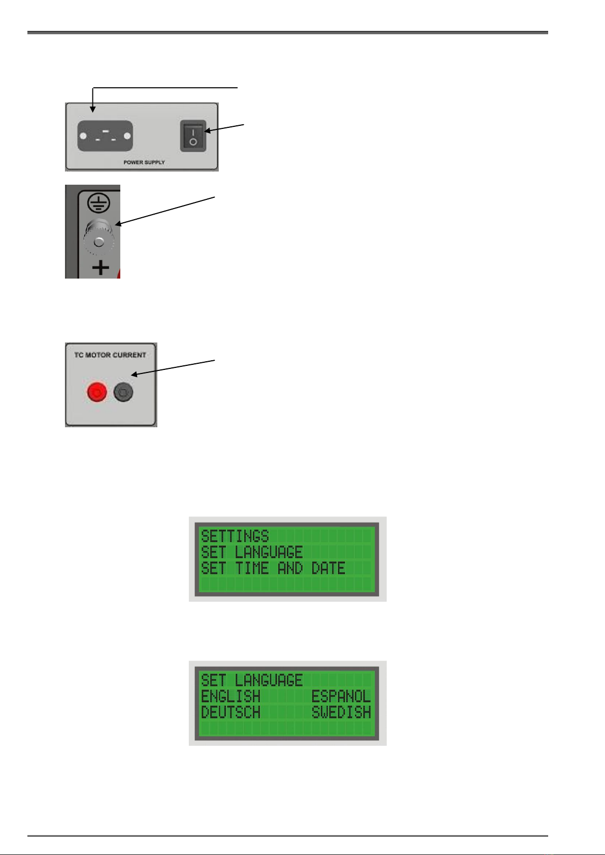
Note: The Voltage sense measuring channels are automatically selected connecting measuring cables
to those channels.
At the start of each test a check of cable continuity is done. In case of open circuit, an alarm is activated,
and the error message is shown on the display.
The test is started by pressing the START button. The RMO60TD injects current with a voltage as high
as 60 V. This ensures the test to be as short as possible and that the desired test current is reached
faster.
When the current is stabilized, RMO60TD measures the resistance of the test object. The test result is
displayed as R=U/I. During the testing period, a new result is shown on the display approximately each
second.
Tests could be finished or interrupted two ways:
- Pushing the STOP button,
- Automatically, after the selected time has expired.
In both cases, upon completion of the test, a measured value of the resistance is recorded to pre-
selected internal memory location.
Each time the Ωbutton is pushed, results of the resistance, the ripple and the test current value are
stored into the internal memory of RMO60TD, and memory location changes to the next one.
Minimum measurement time is 30 seconds.
By pushing the STOP button test could be completed at any time. When the STOP button is pushed, the
last measured result will remain saved in the internal memory.
After the selected test time has expired, the last result remains saved at selected memory location.
Note: Using DV-Win the results could be stored to a PC, where reading interval of results is adjustable.
Results will be shown in a table in Excel format with an option to perform additional edit and graphic
presentation.
Using DV-Win after the test in order to transfer the results from selected internal memory location to a
PC, will allow transfer of the last test result only.
When the measurement is complete, RMO60TD starts discharging the energy from the inductance.
During current discharging, the red discharge LED is lit and the buzzer is ON. Discharge is complete
when the discharge LED and the buzzer are OFF and when discharging message is disappeared from
the display.
Both, injection of current and discharging energy from the inductance is fully automatically regulated. An
intrinsically safe discharge circuit, with indicator, dissipates the stored magnetic energy rapidly after the
test. The discharging circuit is independent of power supply.
Cooling of RMO60TD is supported by a built-in fan that is automatically activated when the device is
turned on.

6
RMO60TD Designated Use, Functionality
4.2 Tap Changer Test
The TapC menu offers a user friendly way of measuring winding resistance in tap changers. The
RMO60TD test set measures the winding resistance of individual taps of a power transformer’s tap
changer, and checks whether the On-Load Tap Changer (OLTC) switches without a discontinuity. In the
moment the tap is changed from tap to tap, the device detects the sudden, very short drop of the current
flow. A properly working tap changer differs from a malfunctioning one in a discontinuity during the
change, by the magnitude of the current ripple value.
Comparison with ‘’fingerprint’’ results, which were taken when the unit was in a known (good) condition,
and comparing with other phases, allows for an efficient analysis. Disposition of all current ripple
changes (or of the current flow on the graph) depends on a particular transformer and OLTC design, so it
is always recommended to compare results obtained on the same unit with previous measurements.
Note: In TapC menu only Ch:1 is the active channel. Maximum test current selected in the TapC mode is
20 A.
At the start of the test a check of cable continuity is performed. In case of disconnection, an alarm is
activated, and the error message is shown on the display.
Note: Using DV-Win in TapC menu the results could be stored to a PC. By pushing the Ωbutton a
resistance result and current ripple value are stored in internal memory location, and the memory
location is automatically increased to the next one.

7
RMO60TD Description
5 Description
5.1 Front Panel Components
STOP
Press to stop a test or stop the alarm buzzer.
START
Press to start a test
Test parameters must be selected beforehand
Pressing START at the same time with SET allows you to go to setting menu for the language, time and
date settings.
Ω
Press to measure the resistance current value.
Press to measure the resistance value in TapC mode
Green LED
• Lights continuously when RMO60TD is turned on.
• Flashes when a test can be started.
• Flashes alternately with the red LED during a test.
Red LED
• Lights continuously in case of operational error.
• Lights continuously during discharging process.
• Flashes alternately with the green LED during the Current test.
• Flashes shortly during resistance measurement in the TapC test.
• Flashes alternately with the green LED during the TapC test.
Red LED - Discharge
• The red LED just above the red output connector remains lit until the accumulated energy of the
measured object is reduced to a harmless level
CAUTION
Within the period when the discharge LED lights it is prohibited to disconnect measuring cables.
The discharge diode cannot be switched off by pressing STOP.
Display
ENTER button to
confirm the defined test
parameters, Language,
Time and Date
START button to
start the test
current.
Ωbutton to measure the
resistance current value and the
resistance and the ripple value in
TapC mode.
STOP button to stop a test, to
acknowledge the alarm buzzer and
return to the Curr menu.
RIGHT button to navigate in
the active menu
UP/DOWN buttons
to select a menu
and set test
parameters
SET button to
scroll between
Current menu,
TapC menu,
Dem menu and
the Memory
menu

8
RMO60TD Description
5.2 Mains power and ground connectors
Motor Current connector
5.3 Settings
To set RMO60TD’s language, time and date press START at the same time with SET, to select the
Setting menu.
Setting RMO60TD’s Language
To set RMO60TD’s language, use RIGHT, and then ENTER to select the Set Language menu.
Move the cursor to the bottom line using RIGHT, and select the language with ENTER.
Pressing ENTER to confirm returns you to the Main menu.
Pressing STOP to cancel returns you to the Main menu.
Connector for mains power supply
Power switch
I In this position, RMO60TD is connected to the
mains power supply.
0 In this position, RMO60TD is separated from
the mains power supply with both poles.
Earth/ground connector.
For protection against parasitic currents or voltages, always connect
RMO60TD earth/ground connector to protective ground (PE). Use
only the original cable.
For safety reasons, always establish this connection as the first
one before you do any other connections, and separate this
connection as the very last one.
Figure 5-2:
The Language
menu
Figure 5-1:
The Settings menu
AC current monitoring channel is intended for monitoring and
recording the OLTC mechanical-drive motor-current during tap
changer operation. The motor current waveform is also printed on the
DV Win generated graph, and can help in detecting OLTC mechanical
problems. An AC current clamp is available for purchase.

9
RMO60TD Description
Setting RMO60TD’s Time and Date
To set RMO60TD’s internal time and date, use RIGHT, and then ENTER to select the Set Time and Date
menu.
Move the cursor to the position of your choice using RIGHT and change the value with ENTER.
Pressing ENTER to confirm, returns you to the Main menu.
Pressing STOP to cancel, returns you to the Main menu.
Figure 5-3:
The Time menu showing
RMO60TD’s internal
time and date

10
RMO60TD Getting Started
6 Getting Started
6.1 Current test
Connecting a Test Object to the RMO60TD
Before you connect a test object to RMO60TD, make sure that:
•The test object is disconnected or separated from its circuit in accordance with the national safety
regulations and is properly grounded to protective earth.
•RMO60TD itself is properly grounded. To do so, connect the grounding screw to PE using a
grounding cable.
•One end of measured windings is properly grounded. An only exception is the case when YN
connection is tested and Neutral and Earth bonds are connected between each other. Only in this
case one side of the measurement circuit must not be earthed because it is not necessary and it will
affect the RMO60TD reading incorrectly.
•See example of a two channel setup in the figure below (6-1).
C A U T I O N
FOR SAFETY REASONS, ALWAYS ESTABLISH A CONNECTION OF THE DEVICE WITH
TEST OBJECT IN THE WAY AS DESCRIBED IN THE FIGURE 6-1.
DO NOT CONNECT MEASURING CABLES AFTER TEST STARTS.
DO NOT DISCONNECT ANY LEADS BEFORE THE LED DISCHARGE AND THE BUZZER
ARE OFF.
The Figure 6-2 shows simultaneous testing of both windings (high and low) on a single-phase
transformer. In such a way, it is possible to speed up the measurement when two channels are used to
test both windings of the transformer.
When performing a two channel measurement; connect the Current connection cable as in the example
below (Figure 6-2.) and outside the Sense leads.
Figure 6-1:
Connecting a test
object to RMO60TD
With RMO60TD turned off, connect RMO60TD
to the test object in such a way that the
measuring cables from the "Voltage Sense"
sockets are attached as close as possible to RX,
and in between the current feeding cables. That
way, resistance of both cables and clamps is
almost completely excluded from the resistance
measurement. Pay attention to polarity while
connecting measuring cables.
To maximize accuracy and measurement
repeatability; make sure that all clamps have a
good connection to the test object and avoid any
connection between Sense and Current clamps.

11
RMO60TD Getting Started
Testing of a Delta-delta winding resistance is usually a very time consuming procedure. This is because
the two windings resemble two closed loop inductors. When energy is brought into the inductors, this
energy (in the form of DC current) continually circulates within each winding. A method to quickly test
this configuration requires that both the high side and low side are connected in series with the Winding
Ohmmeter. By having these two windings in opposing polarity, the internal circulating currents settle very
quickly to obtain a balance, and discharge with the same speed. Even if only one side of the transformer
needs to be tested, connecting both high and low windings in series will speed up the test considerably.
On/Off
Connect the earth/ground lead first before doing any connections to the test object.
Connect the mains lead to a mains outlet 100 V –240 V AC and turn on RMO60TD with the power
switch on the back of the test set. The first shown on the display is the name of the product followed by
the instrument model type and the internal firmware version.
Figure 6-2:
Connecting a test
object to RMO60TD
Figure 6-3:
Connecting a test
object to RMO60TD

12
RMO60TD Getting Started
Setting the Measurement Parameters
Directly after the first display RMO60TD automatically changes to the Current menu and the
green LED lights up.
Before a test can be started, the following needs to be defined in the Current menu:
Test current; the following values can be chosen:
5 mA, 10 mA, 50 mA, 100 mA, 500 mA, 1 A, 2 A, 5 A, 10 A, 15 A, 25 A, 30 A, 40 A, 50 A and
60 A.
Memory position, 000-499
Test duration time.
In the Current menu, define a test current for the test (here 500 mA). To do so, set the value of your
choice by means of the UP/DOWN buttons. Define the test duration time and then the memory position
(here MEMORY:123).
Using RIGHT move the cursor to the memory location position, and using UP/DOWN select the desired
memory position to which obtained results would be saved. Once the test is completed (either due to
time expiration or when pushing STOP) the last measured result will remain registered in RMO60TD, and
the memory position is automatically switched over to the next memory position. The result can be
recalled later by selecting that position number.
Using RIGHT button move the cursor to the test duration position, and using UP/DOWN select desired
value.
Measuring with RMO60TD
Before a test can be started, test current, memory position and the test duration time need to be defined
using the Current menu.
Once these parameters are defined, press ENTER to change to the Ready state.
The Ready state displays the selected test current and its duration is defined. If one of these values has
to be changed, press STOP to return to the Current menu.
The flashing green LED indicates that RMO60TD is now ready to start the test. Press START to run
a test. At the start of the test, a cable connection check is done. In case of e.g. a disconnection, an
alarm is activated and the error message is shown on the display.
During the test, both the green and the red LEDs flash alternately. When the current is stabilized,
RMO60TD starts the measurement of the test object resistance.
Figure 6-4:
The Current
menu
Test current
Memory position
Test duration time
Menu name
Figure 6-5:
The Ready state
before the test
Memory
Time and Date

13
RMO60TD Getting Started
The display shows test current (here 498 mA) and the effective value of the measured resistance (here
567,2 mΩ on channel 1 and 567,3 mΩ on channel 2). The time remained until the end of test procedure is
also shown on the display (here 119 min and 49 sec). It is also shown deviation of resistance ∆R.
Test could be completed in two ways:
- Pushing the STOP button,
- Automatically after the selected time has expired.
When the test is finished either because selected time has expired or the STOP button is pressed,
the RMO60TD switches to the Results menu and starts current discharging process. During
current discharging, the discharging LED lights and the alarm beep.
Discharge is completed when LED discharge and the buzzer are OFF. Also, during that period
“Discharging” message is shown on the display. During discharging process it is not possible to
start another measurement.
Once the test is completed the last measured result will remain registered at a selected memory location
(000-499 memory locations).
Discharge Current
The voltage at the RMO60TD output generation is immediately stopped, but current still flows, because
of the inductivity of test objects.
Because of the enormous amount of energy that can be stored in a magnetic field, precautions should
be taken before disconnecting the test leads from the transformer that is under test. Never remove the
leads during the testing process and always allow enough time for the transformer being tested to
completely discharge. Large transformers can require several minutes to discharge.
C A U T I O N
DO NOT DISCONNECT LEADS BEFORE “DISCHARGING” MESSAGE IS DISAPPEARED
FROM THE DISPLAY AND THE DISCHARGING DIODE IS OFF.
Figure 6-6:
The Current
menu during
the test
Figure 6-7:
The Results menu
showing the test results
Memory
Figure 6-8:
Discharging message

14
RMO60TD Getting Started
Note:
Using DV-Win the results could be stored to a PC, where reading interval results is adjustable. Results
will be shown in a table in Excel format with an option to perform additional edit and graphic
presentation.
Using DV-Win after the test in order to transfer the results from selected internal memory location to a
PC will allow transfer of the last test result only.
Measurement parameters
Typical accuracy given below is valid if the maximum possible current is used.
Range
Test
Current
Resistance
Full Range
Display
Resolution
1
60 A
1 mΩ
999,9 µΩ
0,1 µΩ
2
60 A
10 mΩ
9,999 mΩ
1 µΩ
3
60 A
100 mΩ
99,99 mΩ
10 µΩ
4
60 A
166 mΩ
166,6 mΩ
0,1 mΩ
5
50 A
290 mΩ
290,0 mΩ
0,1 mΩ
6
40 A
375 mΩ
375,0 mΩ
0,1 mΩ
7
30 A
667 mΩ
667,0 mΩ
0,1 mΩ
8
20 A
1,25 Ω
1,250 Ω
1 mΩ
9
10 A
2,5 Ω
2,500 Ω
1 mΩ
10
5 A
5 Ω
5,000 Ω
1 mΩ
11
2 A
5 Ω
5,000 Ω
1 mΩ
12
1 A
15 Ω
15,00 Ω
10 mΩ
13
500 mA
20 Ω
20,00 Ω
10 mΩ
14
100 mA
100 Ω
99,99 Ω
10 mΩ
15
50 mA
200 Ω
199,9 Ω
0,1 Ω
16
10 mA
1 kΩ
999,9 Ω
0,1 Ω
17
5 mA
2 kΩ
2000 Ω
1 Ω
The highest resolution of the reading is always displayed; resistance range selection is performed
automatically and therefore is not necessary to be set by the operator.
Accuracy
Typical accuracy of RMO60TD is ±(0,2 % rdg + 0,2 % FS). This accuracy is valid if the maximum
possible current is used. Always try to use as high current as possible, but to avoid the risk of heating the
winding, it is recommended not to exceed from 10 % to 15 % of the nominal current of transformer. It is
important to get a good connection between clamps and the connecting point on the test object to
achieve stable and accurate test results. Guaranteed accuracy is ±(0,4 % rdg + 0,4 % FS).
Viewing the Test Results
Once a test is finished, RMO60TD automatically changes to the Results menu to display the test results.
Figure 6-9:
The Results
menu showing
the test results
Test current
Memory position that holds the results
Measured resistances of the test objects

15
RMO60TD Getting Started
6.2 Tap Changer test
The winding resistance of individual taps of a power transformer’s tap changer can be measured by
using RMO60TD’s Tap Changer (TapC). Also, it can be used to control the transformer tap changer.
This is a user-friendly way of winding resistance measurement and tap changer control, since automatic
measurement is possible without need to remove the current between each tap change. If the tap
changer is faulty, this may cause damage to the instrument. In order to avoid this, the inputs of the
instrument are protected during switching.
From the Current outputs, RMO60TD injects a constant current into the power transformer. From this
current value and the voltage measured, the winding resistance is calculated. An interruption caused by
a defective tap changer results in a comparatively high measured values of current ripple.
Setting the Measurement Parameters
Turn on RMO60TD with the power switch on the back of the test set. The display shows the
Current menu and the green LED lights up. Press SET to go to the TapC menu.
In the TapC menu, define a test current for the test (here 10 A). The following values can be
chosen: 1 A, 2 A, 5 A, 10 A, 20 A.
To do so, set the value of your choice by means of the UP/DOWN buttons. In the TapC menu of
RMO60TD, current output value is rated continuously at 20 A or less. Define the memory position (here
MEMORY:123). Using RIGHT move the cursor to the memory location position, then using UP/DOWN
select desired memory position to which obtained results would be saved.
By pushing Ω, resistance and current ripple measured results will remain registered in internal memory
of RMO60TD, and the memory position is automatically switched over to the next memory position.
These results can be recalled later by selecting that position number.
Note: Only Ch:1 (left channel) is active channel.
Figure 6-10:
Connecting a test
object to RMO60TD
Figure 6-11:
The TapC
menu
Test current
Memory position
Menu name
Active channel
Time and Date

16
RMO60TD Getting Started
Tap Changer test with RMO60TD
Before a test can be started, test current and memory position need to be defined using the TapC menu.
Once these parameters are defined, press ENTER to change to the Ready state.
The Ready state displays the selected test current and memory location. If one of these values has to be
changed, press STOP to return to the TapC menu.
The flashing green LED indicates that RMO60TD is now ready to start the test. Press START to run
a test. At the start of the test, a cable connection check is done. In case of e.g. a disconnection, an
alarm is activated and the error message is shown on the display
During the period of current stabilization, both the green and the red LEDs flash alternately and
message “WAIT” is shown on display.
When the current is stabilized, the device shows test current (here 9,98 A) and the value of the measured
resistance (here 567,2 mΩ).
At the moment the resistance result is stable, press Ωto save the resistance result of the Tap Changer
starting position. The memory position is automatically switched over to the next one and device is ready
to record the current ripple.
During saving the resistance the red LED flashes shortly and beeper sound is speeded up.
Change the Tap Changer position to the next tap by pushing "Up" or "Down" of the tap changer control.
Because the resistance is changed, current will be unstable and RMO60TD will sample and hold the
largest measured current ripple that occurred in the actual measuring cycle. It is indicated as RIPPLE
(%) with reference to the test current.
Figure 6-12:
The Ready state
before the test
Figure 6-15:
The TapC menu,
memory position is
increased for one
Figure 6-13:
The TapC
menu when the test
current is stabilized
Figure 6-14:
The TapC menu,
change the tap
position

17
RMO60TD Getting Started
The display shows the value of the test current in new tap position (here 9,82 A), and the value of the
current ripple occurred during the change from previous position to the new one (here 4,7 %). At the
moment the test current shown on the display is stable, the RMO60TD shows the resistance value in
new tap position (here 569,8 mΩ). Press Ωto save the resistance and the ripple in the new position of
Tap Changer.
Repeat this procedure as often as needed until the results for RIPPLE and RESISTANCE are obtained
for all Tap Changer positions.
Test is completed pushing STOP.
When measurement is completed (after pressing STOP) RMO60TD switches to the TapC menu
and starts current discharging. During the current discharging process, the discharging LED lights
and alarms beep.
Discharge is completed when LED discharge and the buzzer are OFF. Also, during that period
“Discharging” message is shown on the display. During discharging process it is not possible to
start another measurement.
A properly working tap changer differs from malfunctioning one in a current discontinuity during the tap
change, by the magnitude of the current ripple value. A discontinuity will result in much higher current
ripple value (99 % or 100 %) than a properly functioning tap changer.
Note: Current ripple value depends on the construction of the tap changer. It is recommended to
compare current ripple values between each other got on one transformer. Also, it is recommended to
compare current ripple results on one transformer with results from some previous test in order to follow
conditions of that tap changer.
Figure 6-17 shows indication about possible tap changer bad conditions during the change from tap to
tap.
If current circuit is opened during the change from tap to tap, message „Discontinuity“ will be shown on
the display, red LED will light and buzzer will beep continuously. Discharging process starts.
Figure 6-16:
The TapC menu during
discharging
Figure 6-17:
The TapC menu
showing much higher
current ripple value

18
RMO60TD Getting Started
Discharge Current
The voltage at the RMO60TD output generation is immediately stopped, but current still flows, because
of the inductivity of test objects.
Because of the enormous amount of energy that can be stored in a magnetic field, precautions should
be taken before disconnecting the test leads from the transformer that is under test. Never remove the
leads during the testing process and always allow enough time for the transformer being tested to
completely discharge. Large transformers can require several minutes to discharge.
C A U T I O N
DO NOT DISCONNECT LEADS BEFORE “DISCHARGING” MESSAGE DISAPPEARS FROM
THE DISPLAY AND THE DISCHARGING DIODE AND BUZZER ARE OFF.
Note:
Using DV-Win the results could be stored to PC, where reading interval results is adjustable. Results will
be shown in a table in Excel format with an option to perform additional edit and graphic presentation.
Using DV-Win after the test in order to transfer the results from selected internal memory location to PC
will allow transfer of the last test result only.
Using DV-Win software it is possible to draw a graph which represent dynamic resistance during the
change from tap to tap (refer to section 7.6).
6.3 Demagnetization feature
Note: Before using the demagnetization feature, you must unplug the voltage sense cables from the
device.
After the test is done, there is a feature to demagnetize the transformer under test.
To do so, press SET consecutively until the DEM menu is selected. Once you are in the DEM menu, you
can select the starting current for the demagnetization process by pressing UP/DOWN. We recommend
that the starting current is the same as what was used for the measurement of the transformer under
test. Therefore, the test current used for the last test is displayed as default.
When the current is selected, press ENTER to confirm selection.
Press START to start the demagnetization process. The demagnetization of the transformer under test
will be carried out automatically. It is necessary to disconnect the voltage sense cables before the
Figure 6-18:
Message
"Discontinuity"
Figure 6-19:
Demagnetization
starting current"
Figure 6-20:
The “Ready” state
before the test

19
RMO60TD Getting Started
process begins. If it is not done before START is pressed, a warning message will be displayed and
demagnetization will not start. During the demagnetization process there will be visible message on the
display showing the progress of the demagnetization.
Note:
Never remove the current leads during the demagnetization process and always allow enough time for
the transformer being tested to completely demagnetize. Large transformers can require several minutes
to demagnetize. During the demagnetization process the transformer will be charged and discharged
several times. Once the demagnetization process is finished, the RMO60TD device displays the
message “Demagnetization done!”
Attention:
When the demagnetization process is manually stopped by pressing STOP, it is highly recommended to
follow the discharging LED and the buzzer and to be aware of the danger during the discharging
process.
6.4 Tap Changer Control Unit
The external Tap Changer Control cable is used for convenient tap changer testing.
After the RMO60TD has measured a tap it stands by waiting for the operator to move the transformer tap
changer to the next tap position and continue the measurement by pressing OMEGA on the unit.
The tap changer operation box on power transformers is normally not placed at the same place where
the RMO60TD is placed. The Tap Changer Control Unit block allows the operator to continue the next
tap measurement from the RMO60TD position. It is performed by pressing UP/DOWN on the Tap
Changer Control Unit.
The operator has to connect the Tap Changer Control cable from the RMO60TD to the tap changer
operation box. An example of that connection is shown on the figure below.
Figure 6-21:
Demagnetization menu
during demagnetization
Figure 6-22:
The demagnetization
menu after the process
is finished

20
RMO60TD Getting Started
The Tap Changer Control Unit is actually a pair of relays, one for the UP direction, and one for the
DOWN direction. The brown wire is common for both relays. Pressing the UP button closes the relay
between the yellow wire and the brown wire. Pressing the DOWN button closes the relay between the
green wire and the brown wire.
When the appropriate connection is done, the operator has just to press UP/DOWN on the Tap Changer
Control Unit to change the tap position.
6.5 External data exporting to USB flash drive
To export the data from internal memory of RMO60TD device to the USB flash drive, plug in the USB
flash drive into the RMO60TD device and press PRINT button. The RMO60TD will display the USB flash
drive menu is it is shown on the screen below.
Move the cursor from the Test Record position to the Test Reading position pressing SET. Select the
Test Reading/Record in between the result will be exported to the USB Flash drive. The results that are
located in the range between these memory locations (Test Readings/Records), including the chosen
memory locations, will be transferred to the USB Flash drive.
The file which is saved to the USB Flash drive is automatically named by the date of the test.
Figure 6-24: USB FLASH
DRIVE menu
Figure 6-23: Connecting
Tap Changer Control
cable
Tap Changer
Control Unit
inside the
RMO60TD
Table of contents
Other DV Power Measuring Instrument manuals

DV Power
DV Power RMO600 User manual

DV Power
DV Power RMO200D User manual

DV Power
DV Power RMO200 User manual

DV Power
DV Power RMO100A User manual

DV Power
DV Power RMO500 User manual

DV Power
DV Power RMO30T User manual

DV Power
DV Power RMO100G User manual

DV Power
DV Power BVR11 User manual

DV Power
DV Power RMO40TD User manual

DV Power
DV Power RMO-H User manual
Popular Measuring Instrument manuals by other brands

Hioki
Hioki CM3289 instruction manual

Welker
Welker GSS-4PM Installation, operation and maintenance manual

Honeywell
Honeywell E-Mon Class 1000 quick start guide

Agilent Technologies
Agilent Technologies 16089E Operation note

McCrometer
McCrometer Dura Mag Quick start installation guide

Leine & Linde
Leine & Linde 800 Series user guide