Hioki IM7585 Series Use and care manual

EN
Communication Instruction Manual
IMPEDANCE ANALYZER
IM7581
IM7580A
IM7585
IM7583 IM7583-01
IM7583-02
IM7585-01
IM7585-02
IM7580A-1
IM7580A-2
IM7581-01
IM7581-02
www.calcert.com [email protected]1.888.610.7664 0
5
10
15
20
25
30

Contents
i
Appendix
Index
Contents
Introduction..................................................................................................1
Safety Information .......................................................................................1
Chapter 1 Specifications 3
1.1 RS-232C Specifications ..................................................................3
1.2 GP-IB Specifications .......................................................................4
1.3 USB Specifications .........................................................................4
1.4 LAN Specifications ..........................................................................4
Chapter 2 Connection and Setting 5
2.1 Overview of Communication ...........................................................5
2.2 USB Settings and Connection ........................................................7
Setting USB ......................................................................................................7
Connecting the USB Cable ..............................................................................8
2.3 LAN Settings and Connection .........................................................9
LAN Settings ....................................................................................................9
Connecting a LAN Cable ................................................................................14
2.4 GP-IB Connection and Settings
(when the Z3000 is connected) ....................................................15
Connecting the GP-IB Cable ..........................................................................15
Setting GP-IB .................................................................................................15
2.5 RS-232C Connection and Settings
(when the Z3001 is connected) ....................................................17
Connecting the RS-232C Cable .....................................................................17
Setting RS-232C ............................................................................................18
2.6 Remote Mode ...............................................................................19
Appendix A 1
Appendix 1Checking the USB Virtual COM Port ............................... A 1
1
2
3
4
5
6
7
8
9
10
索
引
11
12
IM7585A987-01
www.calcert.com [email protected]1.888.610.7664 0
5
10
15
20
25
30

1
This instruction manual provides details on the communication interfaces of the IM7580A series, IM7581
series, IM7583 series and IM7585 series Impedance Analyzer.
In this document, the "instrument" means the IM7580A series, IM7581 series, IM7583 series and IM7585
series.
This manual contains information and warnings essential for safe operation of the instrument and for main-
taining it in safe operating condition. Before using it, be sure to carefully read the following safety precautions.
The following symbols in this manual indicate the relative importance of cautions and warnings.
Introduction
Safety Information
Safety Symbols
Indicates that incorrect operation presents a significant hazard that could result in seri-
ous injury or death to the user.
Indicates that incorrect operation presents a possibility of injury to the user or damage to
the product.
Advisory items related to performance or correct operation of the product.
Notation
Symbols in this manual
Indicates the prohibited action.
p. Indicates the location of reference information.
* Indicates that descriptive information is provided below.
[ ] Menus, commands, dialogs, buttons in a dialog, and other names on the screen and the keys are
indicated in brackets.
CURSOR
(Bold character)Bold characters within the text indicate operating key labels.
Windows Unless otherwise specified, “Windows” represents Windows Vista, Windows 7, Windows 8 or
Windows 10.
Dialogue Dialogue box represents a Windows dialog box.
Mouse Operation
Click: Press and quickly release the left button of the mouse.
Right-click: Press and quickly release the right button of the mouse.
Double click: Quickly click the left button of the mouse twice.
Drag: While holding down the left button of the mouse, move the mouse and then release the left button
to deposit the chosen item in the desired position.
www.calcert.com [email protected]1.888.610.7664 0
5
10
15
20
25
30

1.1
RS-232C Specifications
3
Chapter 1 Specifications
XON/XOFF control:
•When the data in the receive buffer exceeds 75% of
the buffer, XOFF(13H) is sent and the controller is
notified that there is not much space remaining in the
buffer.
•Processing of the data in the buffer continues, and
then XON(11H) is sent and the controller is notified
that there is sufficient remaining space in the buffer
when the amount of data becomes less than 25%.
XON/XOFF control:
•When XOFF is received, the sending of data is halted. When XON is received, the sending of data is
resumed.
Specifications Chapter 1
1.1 RS-232C Specifications
Transmission Method Communication method: Full duplex
Synchronous method: Start-stop synchronization
Transmission Speed 9600 bps, 19200 bps, 38400 bps, 57600 bps
Data Bits 8 bits
Parity None
Stop bit 1 bits
Message terminator
(delimiter) CR+LF, CR
Flow control Software (XON/XOFF control)
"Handshake (About Buffer Flow Control)" (p.3)
Electrical
Specifications
Input voltage
level
Output voltage
level
5 to 15 V ........ ON
-15 to -5 V .......OFF
5 to 9 V .......... ON
-9 to -5 V ........ OFF
Handshake (About Buffer Flow Control)
Control during Receiving
25%
85%
Input Buffer
Usage
Amount
Buffer Space
75%
Send XOFF Send XON
Control during Sending
www.calcert.com [email protected]1.888.610.7664 0
5
10
15
20
25
30

1.2 GP-IB Specifications
4
Code used: ASCII code
1.2 GP-IB Specifications
SH1 Supports all source handshake functions.
AH1 Supports all acceptor handshake functions.
T6 Supports standard talker functions.
Supports serial poll functions.
Talk only mode is not supported.
Supports the talker cancel function by MLA (My Listen Address).
L4 Supports standard listener functions.
Listener only mode is not supported.
Supports the listener cancel function by MTA (My Talk Address).
SR1 Supports all service request functions.
RL1 Supports all remote/local functions.
PP0 Parallel poll functions are not supported.
DC1 Supports all device clear functions.
DT1 Supports all device trigger functions.
C0 Controller functions are not supported.
1.3 USB Specifications
Connector Series B receptacle
Compliance standard USB2.0 (Full Speed/High Speed)
No. of ports 1
Class Communication class
Supported OS Windows Vista, Windows 7 , Windows 8, Windows 10
1.4 LAN Specifications
Connector RJ-45 connector ×1
Compliance standard IEEE 802.3-compliant Ethernet
Transfer system 10BASE-T/ 100BASE-TX/ 1000BASE-T Auto detected
Protocol TCP/IP
Function Command control
www.calcert.com [email protected]1.888.610.7664 0
5
10
15
20
25
30

2.1
Overview of Communication
5
Chapter 2 Connection and Setting
You can control the instrument with communication commands from a computer via the USB, GP-IB, RS-
232C and LAN interfaces.
There are the following four communication methods. To enable communication, the communication condi-
tions need to be set on the instrument.
The instrument is communication class compatible.
Command control using the TCP/IP protocol is possible.
• Commands common to IEEE-488-2 1987 (requirement) can be used.
• The instrument has been designed with reference to the following standard. (Reference standard:
IEEE-488.2 1987)
Connection and
Setting Chapter 2
2.1 Overview of Communication
• Always turn both devices OFF when connecting and disconnecting an interface
connector. Otherwise, an electric shock accident may occur.
• To avoid damage to the instrument, do not short-circuit the terminal and do not
input voltage to the terminal.
• Failure to fasten the connectors properly may result is sub-specification perfor-
mance or damage to the equipment.
USB communication (p.7)
LAN communication (p.9)
GP-IB communication (when the Z3000 is connected) (p.15)
RS-232C communication (when the Z3001 is connected) (p.17)
www.calcert.com [email protected]1.888.610.7664 0
5
10
15
20
25
30

2.1
Overview of Communication
6
When you set an interface, the icon for the set interface is displayed on the right side of the screen.
Screen Displayed while Setting Interfaces
When USB is set
When GP-IB is set
When RS-232C is set
When LAN is set
www.calcert.com [email protected]1.888.610.7664 0
5
10
15
20
25
30

2.2
USB Settings and Connection
7
Chapter 2 Connection and Setting
The display will vary with the installed options.
2.2 USB Settings and Connection
Setting USB
To connect the instrument to a computer the first time, a dedicated USB driver must be installed.
Before connecting the instrument to the computer, install the USB driver.
The USB driver can be downloaded from the bundled CD, or our web site.(http://www.hioki.com)
The USB driver is compatible with the Windows Vista (32-bit, 64-bit version), Windows 7 (32-bit,
64-bit version), Windows 8 (32-bit, 64-bit version) and Windows 10 (32-bit, 64-bit version) operating
systems.
Additionally, do not put the computer into the sleep state while the instrument is connected to the
computer.
You can configure the setting from any of mode and mode.
Procedure
LCR Measurement Screen
1Interface Settings
Press .
2USB Setting
www.calcert.com [email protected]1.888.610.7664 0
5
10
15
20
25
30

2.2
USB Settings and Connection
8
Connect a USB cable (commercially available USB cable) to the USB port of the instrument.
Connecting the USB Cable
3USB Setting
Select the terminator setting.
CR+LF
CR
Press to confirm the setting.
4
• To avoid faults, do not disconnect or reconnect the USB cable during instrument
operation.
• Connect the instrument and the computer to a common earth ground. Using differ-
ent grounds could result in potential difference between the instrument and the
computer. Potential difference on the USB cable can result in malfunctions and
faults.
• Do not disconnect or connect other USB devices from or to, respectively, PC during
USB communications between instrument and computer. The USB communica-
tions between instrument and PC may stop.
USB cable
(commercially available product)
Type B USB interface port of computer
www.calcert.com [email protected]1.888.610.7664 0
5
10
15
20
25
30

2.3
LAN Settings and Connection
9
Chapter 2 Connection and Setting
You can perform command control using the TCP/IP protocol.
Set the instrument to match your network environment in advance.
Example 1. Connecting the instrument to an existing network
When connecting the instrument to an existing network, the network settings need to be confirmed in
advance.
An IP address which is not the same as that of another network device needs to be assigned.
Confirm the following items with the network administrator, and write them down.
Example 2. Connecting multiple instruments to a single computer using a hub
When building a local network with no outside connection, the following private IP addresses are recom-
mended.
Example of private IP address:
IP Address ...............Computer: 192.168.0.100
Instrument: 192.168.0.1, 192.168.0.2, 192.168.0.3...
(Set an IP address that differs from that of other network devices.)
Subnet Mask............255.255.255.0
Default Gateway ......OFF(0.0.0.0)
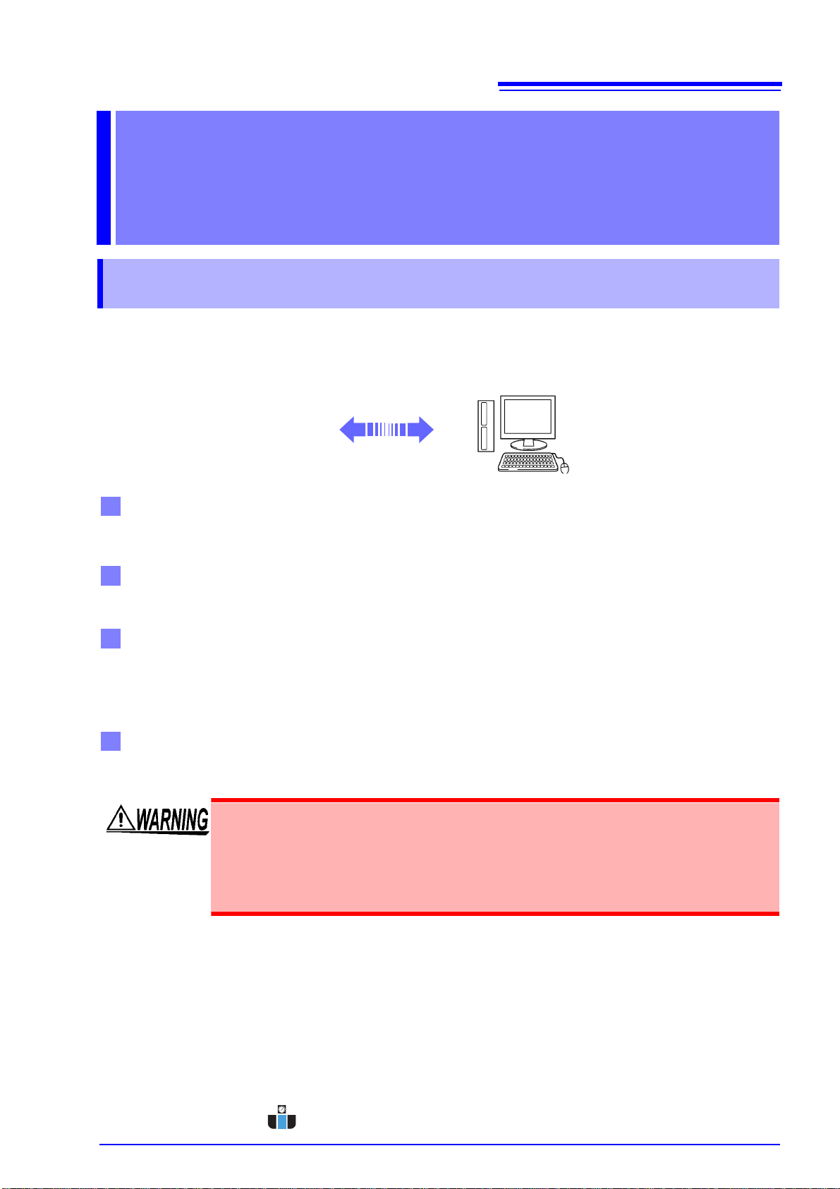
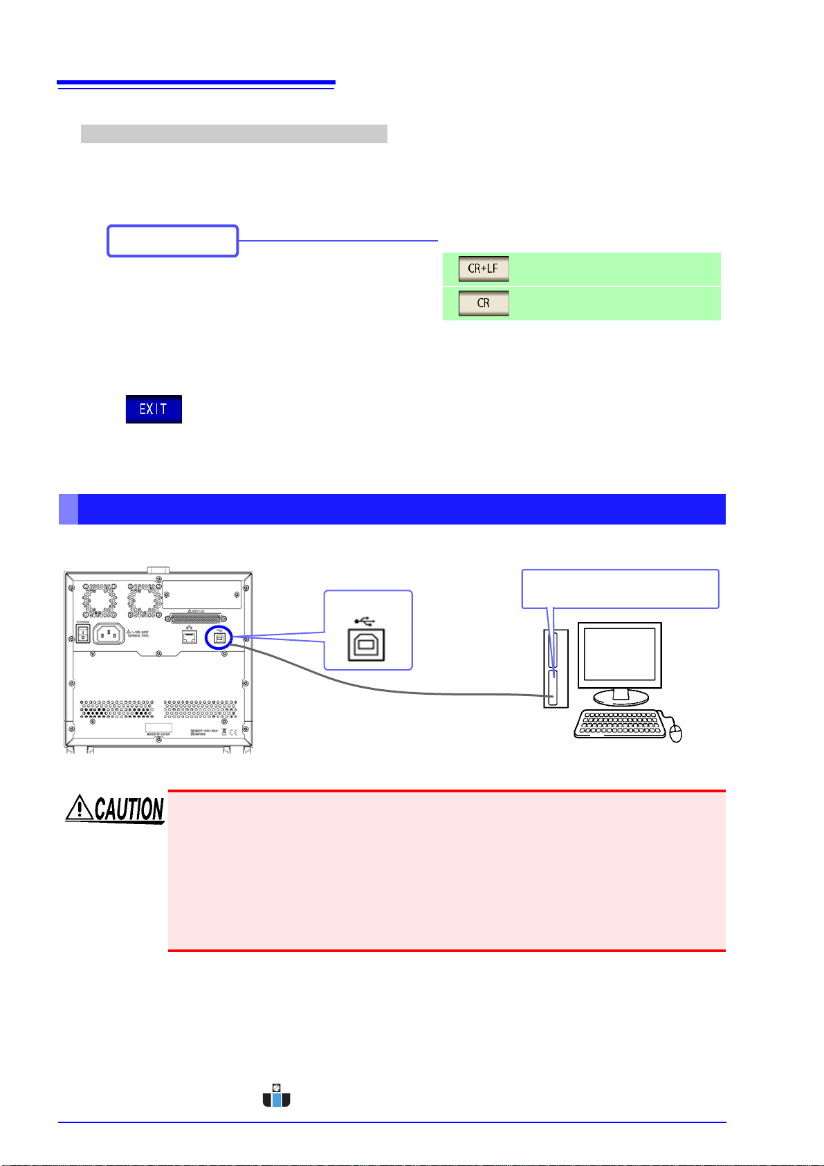
Example 3. Connecting one instrument to a single computer using the 9642 LAN Cable
The 9642 LAN Cable can be used with its supplied connection adapter to connect one instrument to one
computer, in which case the IP address is freely settable. Use the recommended private IP addresses.
IP Address ...............Computer: 192.168.0.100
Instrument: 192.168.0.1 (Set to a different IP address than the computer.)
Subnet Mask............255.255.255.0
Default Gateway ......OFF(0.0.0.0)
2.3 LAN Settings and Connection
LAN Settings
• Make these settings before connecting to a network. Changing settings while connected can
duplicate IP addresses of other network devices, and incorrect address information may other-
wise be presented to the network.
• The instrument does not support DHCP (automatic IP address assignment) on a network.
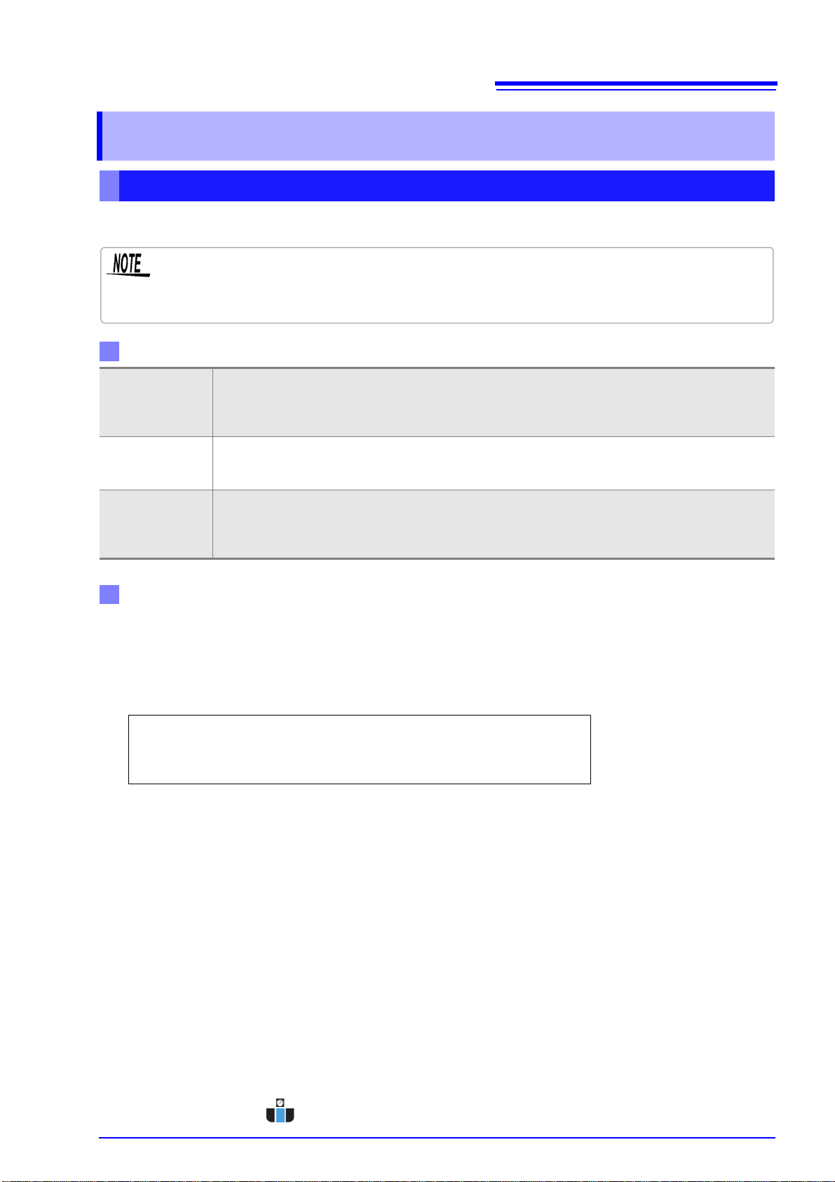
Setting Items
IP address
Identifies each device connected on a network.
Each network device must be set to a unique address.
The instrument supports IP version 4, with IP addresses indicated as four decimal octets, e.g.,
"192.168.0.1".
Subnet mask This setting is for separating the IP address into the network address that indicates the network and
the host address that indicates the instrument. On this instrument, the subnet mask is represented as
four decimal numbers separated by ". " such as "255.255.255.0."
Default Gateway
When the computer and instrument are on different but overlapping networks (subnets), this IP ad-
dress specifies the device to serve as the gateway between the networks.
If the computer and instrument are connected one-to-one, no gateway is used, and the instrument's
default setting "0.0.0.0" can be kept as is.
Network Environment Configuration
IP Address _________._________._________._________
Subnet Mask _________._________._________._________
Default Gateway _________._________._________._________
www.calcert.com [email protected]1.888.610.7664 0
5
10
15
20
25
30

2.3
LAN Settings and Connection
10
You can configure the setting from any of mode and mode.
Procedure
LCR Measurement Screen
1Interface Settings
Press .
2LAN Settings
LAN Settings
3
Select the IP address.
www.calcert.com [email protected]1.888.610.7664 0
5
10
15
20
25
30

2.3
LAN Settings and Connection
11
Chapter 2 Connection and Setting
IP address Settings
4
Use or to set the IP address.
Press to confirm the setting.
LAN Settings
5
Select the subnet mask.
128.000.000.000 255.128.000.000 255.255.128.000 255.255.255.128
192.000.000.000 255.192.000.000 255.255.192.000 255.255.255.192
224.000.000.000 255.224.000.000 255.255.224.000 255.255.255.224
240.000.000.000 255.240.000.000 255.255.240.000 255.255.255.240
248.000.000.000 255.248.000.000 255.255.248.000 255.255.255.248
252.000.000.000 255.252.000.000 255.255.252.000 255.255.255.252
254.000.000.000 255.254.000.000 255.255.254.000
255.000.000.000 255.255.000.000 255.255.255.000
(Initial setting)
Subnet mask Settings
6
Use or to set the subnet mask,
and press to confirm the setting.
Any of the following 30 subnet masks can be set for the instrument.
www.calcert.com [email protected]1.888.610.7664 0
5
10
15
20
25
30

2.3
LAN Settings and Connection
12
LAN Settings
7
Select the default gateway.
If the default gateway does not need to be set, for
example, when connecting the instrument and
computer on a one-to-one basis using a cross ca-
ble, leave this set to OFF.
Default gateway Settings
8
Use or to set the default gate-
way.
Press to confirm the setting.
LAN Settings
9
Select the port number.
www.calcert.com [email protected]1.888.610.7664 0
5
10
15
20
25
30

2.3
LAN Settings and Connection
13
Chapter 2 Connection and Setting
Port number Settings
10
Use or to set the port number to
use for communication commands.
Press to confirm the setting.
Settable range : 1024 to 65535
LAN Settings
11
Select the terminator setting.
CR+LF
CR
Press to confirm the setting.
12
www.calcert.com [email protected]1.888.610.7664 0
5
10
15
20
25
30

2.3
LAN Settings and Connection
14
Use a LAN cable to connect the instrument and computer.
Required items:
When connecting the instrument to an existing network (prepare any of the following):
• Straight-through Cat 5, 1000BASE-T-compliant Ethernet cable (up to 100 m, commercially available).
For 100BASE/10BASE communication, a 100BASE-TX/10BASE-T-compliant cable may also be used.
• Hioki 9642 LAN Cable (option)
(A cross adapter cannot be used.)
When connecting one instrument to a single computer (prepare one of the following):
• 1000BASE-T-compliant cross-over cable (up to 100 m)
• 1000BASE-T-compliant straight-through cable with cross-over adapter (up to 100 m)
• Hioki 9642 LAN Cable (option)
When connecting the instrument to a single computer (connect the instrument to the computer)
Connecting a LAN Cable
On: Link up
Off: Link down
Blinking: Sending or receiving data
On (Green) :1000BASE
On (Orange) :100BASE
Off:10BASE
LINK UP LED
SPEED LED
The MAC address of the LAN is displayed below the serial number.
You can also check it on the instrument screen.
See: "Checking the Version of the Instrument" in the instruction
manual.
LAN interface
Crossover adapter
Connecting with the 9642 LAN Cable and crossover adapter (supplied with the 9642)
1Connect the LAN Cable to the
crossover adapter.
Connect the crossover adapter to
the LAN interface on the instrument.
2
Connect the LAN Cable to the
100BASE-TX connector on the PC.
3
www.calcert.com [email protected]1.888.610.7664 0
5
10
15
20
25
30

2.4
GP-IB Connection and Settings (when the Z3000 is connected)
15
Chapter 2 Connection and Setting
Connect the GP-IB cable to the GP-IB connector.
2.4 GP-IB Connection and Settings
(when the Z3000 is connected)
Connecting the GP-IB Cable
Setting GP-IB
Recommended cable:
9150-02 GP-IB connection cable (2 m)
You can configure the setting from any of mode and mode.
Procedure
LCR Measurement Screen
1Interface Settings
www.calcert.com [email protected]1.888.610.7664 0
5
10
15
20
25
30

2.4
GP-IB Connection and Settings (when the Z3000 is connected)
16
Press .
2GPIB Setting
3GPIB Setting
Use or to set the GP-IB address.
Select the terminator setting.
LF with EOI
LF with CR+EOI
Press to confirm the setting.
4
www.calcert.com [email protected]1.888.610.7664 0
5
10
15
20
25
30

2.5
RS-232C Connection and Settings (when the Z3001 is connected)
17
Chapter 2 Connection and Setting
Connect the RS-232C cable to the RS-232C connector.
(Recommended cable: 9637 RS-232C cable)
Example: Connecting to a DOS/V PC
Specification: D-sub 9-pin female and female connector, reverse connection
2.5 RS-232C Connection and Settings
(when the Z3001 is connected)
Connecting the RS-232C Cable
Male 9-pin D-sub
#4-40 attaching screws
To connect the instrument to a controller (DTE), use a crossover cable
compatible with the connectors on both the instrument and the controller.
The I/O connector is a DTE (Data Terminal Equipment) configuration.
6 7 8 9
1 2 3 4 5
Connector (D-sub)
Pin No. Interchange Circuit
Name CCITT
Circuit No. EIA
Abbreviation JIS
Abbreviation Common
Abbreviation
1Unused
2Received Data 104 BB RD RxD
3 Transmitted Data 103 BA SD TxD
4Data Terminal Ready 108/2 CD ER DTR
5 Signal Ground 102 AB SG GND
6Unused
7Unused
8Unused
9Unused
www.calcert.com [email protected]1.888.610.7664 0
5
10
15
20
25
30

2.5
RS-232C Connection and Settings (when the Z3001 is connected)
18
Setting RS-232C
Procedure
LCR Measurement Screen
1Interface Settings
You can configure the setting from any of mode and mode.
Press .
2RS-232C Settings
3
Press to confirm the setting.
4
RS-232C Settings
Select the handshake setting.
No flow control
Software (XON/XOFF control)
Select the terminator setting.
CR+LF
CR
Select the baud rate setting.
www.calcert.com [email protected]1.888.610.7664 0
5
10
15
20
25
30

2.6
Remote Mode
19
Chapter 2 Connection and Setting
When you connect a device to an interface and start communication, the mode becomes remote mode
(remote operation state) and the keys on the LCD are disabled.
2.6 Remote Mode
Canceling Remote Mode
All of the keys except are disabled.
Remote Mode State
Procedure
2
Press to return to the normal state
(local state).
1
The measurement screen is redisplayed.
Local State
LCR Measurement Screen
www.calcert.com [email protected]1.888.610.7664 0
5
10
15
20
25
30
This manual suits for next models
11
Table of contents
Other Hioki Measuring Instrument manuals