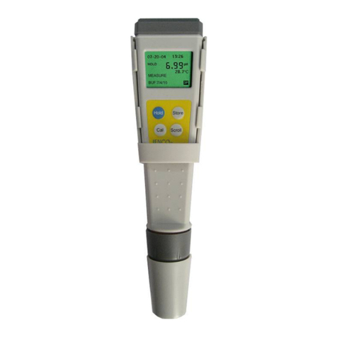
JENCO 9031M User manual

Operation Manual
MODEL 9031M
Basis Portable
DO/Temperature Meter
9031M

1
CONTENTS
GENERAL INTRODUCTION………………....................2
INITIAL INSPECTION……...………………....................2
INSTALLING THE BATTERIES…………....................3
CONNECTOR..............................…………....................3
DISPLAY & KEYS FUNCTIONS…..……………...…………4
A. Display ................................................................4
B. Keys.....................................................................5
THE LSDO PROBE………….……….............................6
A. Probe ................................................................6
B. Preparing the Probe..............................................6
OPERATIONAL PROCEDURES..…….........................8
A. Entering Sensor Cap Coefficients into the 9031M.....8
B. Dissolved Oxygen Calibration.................................9
C. Dissolved Oxygen Measurements..........................10
D. Sampling Modes-continuous or manual.................11
E. Save, Recall and Delete Data.................................11
SENSOR MAINTENANCE……………………………...12
A. Cleaning the Sensor Cap......................................12
B. Sensor Cap Replacement......................................13
C. Sensor Storage....................................................14
ERROR DISPLAYS AND TROUBLESHOOTING.......15
SPECIFICATIONS………………..……........................17
WARRANTY…………………………….........................18

2
GENERAL INTRODUCTION
Thank you for selecting the 9031M meter. The 9031M is a precision
tool that measure dissolved oxygen in % and mg/L and temperature.
A built-in microprocessor stores, calculates and compensates for all
parameters related to DO determinations including DO electrode
temperature characteristics.
This unit has a waterproof IP67 case. The touch mode keys are
highly reliable with tactile and audio feedback. The 9031M up to 2
point calibration. This meter can operate with one 9 V battery.
Re-calibration is not required when power is turned on again.
The front of the meter has a large LCD that displays DO% saturation
or mg/L, and temperature simultaneously along with user prompts
and mode indicators. The unit prompts the user through calibration
and measurement procedures.
The 9031M measures dissolved oxygen in water using optical,
lifetime luminescence technology and uses a digital signal to send
information between the instrument and probe. Key advantages of
the 9031M include the elimination of sensor flow dependence
(stirring) and sensor warm-up time, greater stability, less frequent
calibrations, and the elimination of frequent membrane/electrolyte
changes.
The unit is also equipped with a non-volatile memory allowing the
user to store 50 different sets of readings. This unit will assign a site
number for each set of reading, so the user can review the data
easily.
Other features include long battery life and 50/60 Hz AC noise
rejection. This meter is user-friendly for field, industrial and
laboratory applications.
INITIAL INSPECTION
Carefully unpack the unit and accessories. Inspect for damages
made in shipment. If any damage is found, notify your Jenco
representative immediately. All packing materials should be saved
until satisfactory operation is confirmed.

3
INSTALLING THE BATTERIES
The 9031M meter is packaged with one 9 V battery required for
operation. To insert the batteries into the meter, follow the
procedure outlined below.
Figure 1: Battery compartment
1. Use a screw driver to remove the four screws and battery
cover to expose the battery compartment. (Figure 1.)
2. Replace the 9 V battery.
3. Replace the battery cover and make sure to secure the four
screws for the water-tight feature.
CONNECTOR
Figure 2: 9031M Connector
1. DO connector (6 PIN Waterproof connector)

4
DISPLAY & KEYS FUNCTIONS
A. Display
Figure 3: Active LCD screen
1. -
Low battery indicator.
2. MAIN DISPLAY-
Main display for dissolved
oxygen values.
3. mBar-
Display pressure units in
calibration mode.
4. Data storage site number.
5. CAL-
Calibration mode indicator.
6. K1, K2, K3, K4, K5, KC:
Sensor cap coefficient
indicators when entering
new sensor cap coefficient.
7. Temperature unit. 8. Temperature values
9. mg/L,%-
dissolved oxygen unit.
10. Full, Recall, Each, All,
Delete: Instrument’s data
storage indicators.
11.SAL ppt-
Display salinity units in
calibration mode.
12. CAP-
Sensor cap parameter
setting mode
13.Continuous or Manual-
Continuous or Manual
sampling mode indicator.
14. SAVE-
To save a reading into the
data storage.

5
B. Keys
Mea.
Eff.
Stand
Slope
Mode
Clear
ON/OFF-
Powers on and shuts off the meter.
Mode-
Selects display mode. In normal operation, press this
key to sequentially display Dissolved Oxygen in % air
saturation, Dissolved Oxygen in mg/L, Recall and
Delete interface.
In calibration mode, press this key to exit the current
calibration parameter and enter into the next one.
In “Recall” and “Delete” modes, press this key to exit
“Recall” and “Delete” modes respectively.
Up & Down-
To adjust inputs for salinity correction, calibration and
sensor cap coefficients.
Increases or decreases the display value as desired.
In “Recall” mode, view saved data and data storage
site number by pressing these keys.
In “Delete” mode, press these keys to select between
the “Delete Each” and “Delete All” mode.
In “Delete Each” mode, view to be deleted data and
data site numbers by pressing these keys.
CAL-
In “Measurement” mode, press this key to enter into
“Calibration” mode.
Enter-
In “Calibration” mode, press this key to save the
current parameter to memory.
In “Measurement” mode, press this key to save
reading into the next available data storage site.
At the Recall interface, press this key to display the
last set of saved data.
At the Delete interface, press this key to go into
“Delete” mode.
In the “Delete All” mode, press this key to delete all
saved data.
In the “Delete Each” mode, press this key to delete a
single set of data.
In the “Cap coefficients” mode, press this key to
confirm coefficient entries.
CAP-
Press to enter new sensor cap coefficients.
Mea.
Eff.
Stand
Slope
Mode
Clear
Mea.
Eff.
Stand
Slope
Mode
Clear

6
Sample/MODE-
Press and hold for 3 seconds to switch between
continuous and manual measurement modes.
Press and release to restart the measurement when
in manual mode. Continuous mode: the instrument
will continuously update the dissolved oxygen
measurement. Manual mode: the instrument will
update the DO reading until reaching a stable
measurement. The stable measurement will be
‘locked’ on the display until the user initiates a new
measurement reading by pressing the
“Sample/MODE” key.
THE LSDO PROBE
A. Probe
Throughout the manual, the term “probe” refers to the end of the
cable where the sensor is located, the term “sensor” refers to the
Light Sensing Dissolved Oxygen sensing portion of the cable/probe
assembly, and the term “sensor cap” refers to the removable
sensing cap that is replaced about once per year (Figure 4).
Figure 4: Probe
B. Preparing the Probe
Each 9031M sensor cap has unique calibration coefficients
associated with it. These coefficients are labeled on the instruction
sheet included with each 9031M cable/probe assembly and
replacement 9031M sensor cap.
Remove the probe/cable assembly from the shipping container and
locate the sensor cap instruction sheet. Be sure to save the

7
instruction sheet in case you need to reload these calibration
coefficients. New probe/cable assemblies have the sensor cap
installed and coefficients loaded into the probe at the factory. When
a cable is installed, the coefficients are automatically sent to the
instrument.
Preparing the probe for the first time:
1. Remove the probe guard from the probe by turning it
counterclockwise.
2. Remove the red storage cap which contains a moist
sponge from the end of the probe by pulling it straight off
the sensor. Save this to use later for long term storage.
3. Reinstall the probe guard by sliding it carefully over the
sensor and then threading it onto the cable/probe assembly
with a clockwise rotation (Figure 5).
4. Locate the gray calibration/storage sleeve that was
shipped with your probe/cable assembly. Moisten the
sponge in the gray calibration/storage with a small amount
of clean water.
5. Slide the calibration/storage sleeve over the probe guard to
keep the probe in a moist environment for storage and
calibration (Figure 6). It is important to always keep your
sensor in a moist environment so the sensor cap does not
dry out.
6. Connect the cable to the instrument by aligning the
connectors, pushing them together and then screwing
down the retainer clockwise.
Figure 5 Figure 6

8
OPERATIONAL PROCEDURES
A. Entering Sensor Cap Coefficients into the 9031M
Connect the probe/cable assembly to the instrument and turn the
instrument on. Locate the Calibration Code Label at the top of the
instruction sheet and note the six numbers which are listed as K1
through K5 and KC. These six numbers contain the calibration code
for this particular sensor cap. Follow these instructions to enter the
new calibration coefficients into your instrument:
1. Press and hold the “CAP” key for 3 seconds.
2. The instrument will prompt for K1 and show 8 alpha/numeric
values with the first value blinking.
3. Use the “Up” and “Down” keys to adjust the first value to
match the first value of the new cap’s K1. Press the “Enter”
key to accept.
4. Continue using the “Up” and “Down” keys to adjust all 8
alpha/ numeric values for K1 pressing the “ENTER” key to
confirm each entry.
5. After confirming the last value for K1, the instrument will prompt
you for K2. Follow the instructions in step 3 and 4 to enter and
confirm the value for K2. Continue with K3, K4 and K5.
6. After confirming K5, the 9031M will prompt you for KC. KC has
two values. Follow the instructions in step 3 and 4 to enter the
coefficients. After confirming KC, the instrument will return to
the measurement screen.
7. After entering the Sensor Cap Coefficients, perform a 1-point or
2-point calibration as described in the Calibration Section.
8. Press and hold the “CAP” key for 3 seconds at any time to exit
and cancel the cap coefficient update.
If errors are made in entering the Sensor Cap Coefficients, the
instrument will block the update and an error message will appear
on the display and the instrument will return to the K1 entry screen.
If you see this error message, re-enter the coefficients and check
them carefully for correct transcription from the Calibration
Coefficient Label.

9
The coefficient values are hexadecimal. Due to the 9031M’s display,
6 and b look very similar. Hexadecimal values on the 9031M will be
displayed as: A, b, C, d, E, F, 0, 1, 2, 3, 4, 5, 6, 7, 8, and 9.
If you continue to get an error message after several entry attempts,
contact JENCO Technical Support for assistance.
B. Dissolved Oxygen Calibration
The 9031M offers two options for calibrating dissolved oxygen:
DO% in water saturated air, and a Zero point. If performing a zero
point calibration, you must also perform a DO% calibration following
the zero calibration. For ease of use, JENCO recommends
performing a 1-point DO% water-saturated air calibration.
a. 1-point DO% water-saturated air calibration
1. Connect the LSDO probe to the unit and turn the unit on.
2. Hold the probe in the air gently with the sensor facing down
and press “Mode” key to select “Dissolved Oxygen in %”
mode.
3. Wait 3 to 5 minutes for the dissolved oxygen and temperature
reading to stabilize, press the “CAL” key to enter the
“Calibration” mode. The “CAL” icon appears on the LCD. The
main screen will display “1013 mBar” (factory default value).
The meter is now ready for atmospheric pressure calibration.
4. To change the pressure factor, use the “Up” and “Down”
keys to adjust the value between 500 and 1125 mBar. Press
“Enter” key to save the new value and the unit will
automatically go into the next calibration parameter which is
the value of 100% saturation in air. If “Mode” key is pressed
instead of the “Enter” key, any changes made will be
cancelled and the previous calibration settings will be retained.
5. In this interface, the user can view the calibration value in the
secondary display. Once the value in the main display
stabilizes, press “Enter” key to save the new value and the
unit will automatically go into the salinity compensation
parameter. If “Mode” key is pressed instead of the “Enter” key,
any changes made will be cancelled and the previous
calibration settings will be retained.
6. The salinity default factor value is 0.0 ppt. To change the
salinity compensation factor, use the “Up” and “Down” keys
to adjust the value between 0.0 and 40.0 ppt. Press “Enter”
key to save the new value and the unit will automatically

10
switch to “Measurement” mode. Calibration is now complete. If
“Mode” key is pressed instead of the “Enter” key, any
changes made will be cancelled and the previous calibration
settings will be retained and will automatically switch to
“Measurement” mode.
b. 2-point calibration
1. Connect the LSDO probe to the unit and turn the unit on.
2. Place the sensor in a solution of zero DO.( A zero DO solution
can be made by dissolving approximately 8 ~ 10 grams of
sodium sulfite (Na2SO3) into 500 mL tap water or DI water.
Mix the solution thoroughly. It may take the solution 60 minutes
to be oxygen-free.).Press “Mode” key to select “Dissolved
Oxygen in %” mode.
3. Wait 3 to 5 minutes for the dissolved oxygen and temperature
reading to stabilize, press the “CAL” key to enter the
“Calibration” mode. The “CAL” icon appears on the LCD. The
main screen will display “1013 mBar” (factory default value).
The meter is now ready for atmospheric pressure calibration.
4. To change the pressure factor, use the “Up” and “Down” keys
to adjust the value between 500 and 1125 mBar. Press
“Enter” key to save the new value and the unit will
automatically go into the next calibration parameter which is
the value of 100% saturation in air. If “Mode” key is pressed
instead of the “Enter” key, any changes made will be
cancelled and the previous calibration settings will be retained.
5. In this interface, the user can view the calibration value flashing
in the secondary display. Press "Up" or "Down" key to select
the display to "0.0". Once the value in the main display
stabilizes, press “Enter”key to save the new value and the
unit will automatically go into the second point calibration. If
“Mode”key is pressed instead of the “Enter” key, any
changes made will be cancelled and the previous calibration
settings will be retained.
6. Repeat steps 5 to 6 of “1-point DO% water-saturated air
calibration” for second point calibration.
C. Dissolved Oxygen Measurements
Press “Mode” key to choose the dissolved oxygen in % mode or
dissolved oxygen in mg/L mode. Rinse the LSDO probe with
distilled water and immerse it in the sample to be measured.

11
D. Sampling Mode- continuous or manual
The 9031M sampling mode can be set to Manual or Continuous.
During the “Measurement” mode, press and hold the
“Sample/MODE” key for 3 seconds to switch between
“Continuous” and “Manual” mode. When in “Manual” mode, press
“Sample/MODE” key to initiate a new measurement.
“Continuous” mode: the instrument will continuously update the
dissolved oxygen measurement.
“Manual” mode: the instrument will update the DO reading until
reaching a stable measurement. The stable measurement will ‘lock’
on the display until the user initiates a new measurement by
pressing the “Sample/MODE” key. “Manual” mode conserves
battery power.
E. Save, Recall and Delete Data
a. Saving readings to memory.
1. In “Measurement” mode, press the “Enter” key to save data.
The “Save” icon with the corresponding site number will lit up
for a brief moment to indicate a successful data save.
2. If the “Full” icon is displayed, this means that all 50 data saving
sites are used up. No new data can be saved until existing
saved data are deleted.
b. Recalling readings from memory.
1. To recall saved data, press “Enter” key at the Recall interface
to go into “Recall” mode.
2. Press the “Up” or “Down” keys to select the storage site
number.
3. Press “Mode” key to exit “Recall” mode.
c. Deleting data.
1. Press the “Enter” key at the Delete interface to go into
“Delete” mode.
2. Select “Delete All” or “Delete Each” mode by pressing the
“Up” or “Down” key.
3. In the “Delete All” mode, press “Enter” key to clear all stored
data. Deletion is now complete.

12
4. In the “Delete Each” mode, use “Up” and “Down” key to
select data to be deleted. Then press “Enter” key to delete.
Deletion is now complete. The next set of saved data will
automatically move up a slot in the storage site.
5. Press “Mode” key to exit “Delete” mode.
SENSOR MAINTENANCE
Sensor caps last longer if stored in a moist environment and kept
clean and free of scratches in the paint layer. Erratic readings can
result from damaged or dirty caps. If unstable readings occur from
large scratches in the paint or dye layer, replace the sensor cap.
See the Maintenance and Troubleshooting section of this manual for
information on how to clean or replace the sensor cap. The average
sensor cap replacement interval is 12 to 18 months, although they
may last longer.
Avoid substances that may damage probe materials such as
concentrated acid, caustics and strong solvents. Probe materials
include urethane (cable), Xenoy (probe body), acrylic (sensor cap)
and acetal and stainless steel (probe guard).
To prevent the sensor cap from drying out, store the probe in the
gray calibration/storage sleeve with a moistened, clean sponge. In
the event the sensor cap dries out, rehydrate it following the
instructions in the Maintenance and Troubleshooting section of this
manual.
A. Cleaning the Sensor Cap
The Sensor Cap should be kept clean since some types of fouling
can consume or produce oxygen or block the water sample from
reaching the sensor which could affect the dissolved oxygen
measurements.
To clean the Sensor Cap, gently wipe away any fouling with a lens
cleaning tissue that has been moistened with water. Do not use
organic solvents to clean the Sensor Cap. Using an organic solvent
to clean the Sensor Cap may cause permanent damage to the cap.
For example, alcohol will dissolve the outer paint layer and other
organic solvents will likely dissolve the dye in the cap. Dissolving or
scratching the paint or dye layer will cause erratic dissolved oxygen
measurements.
To disinfect the probe, soak the probe in 3% hydrogen peroxide for
15 to 30 minutes and then rinse it with clean water.

13
B. Sensor Cap Replacement
The sensor cap should be replaced about once per year but may
last longer. It should also be replaced if it is cracked or damaged
(see Troubleshooting section for instructions on how to inspect the
cap for damage). The instruction sheet shipped with the
replacement LSDO sensor cap includes the calibration coefficients
specific to your sensor cap.
The replacement LSDO sensor cap is shipped in a humidified
container. The package should not be opened until ready for use.
Once the sensor cap has been installed on the sensor as described
below, it is important to keep the sensor in a 100% humid
environment. Therefore, the sensor should be stored in either the
gray calibration/storage sleeve with a moistened sponge or
immersed in water, see Sensor Storage for more information. If the
sensor dries out, refer to the Rehydration procedure in this manual.
Refer to Figure 7 below when following the instructions for replacing
the cap.
[Note: Avoid touching the sensing end of the sensor cap during the
following maintenance procedures.]
Figure 7
1. Remove the old sensor cap assembly from the sensor by
grasping the probe body with one hand and then rotating the
sensor cap counterclockwise until it is completely free. Do not
use any tools for this procedure.
2. Inspect the o-ring on the probe for damage. If there is any
indication of damage, carefully remove the o-ring and replace
it with the new o-ring included with the replacement sensor
cap. Do not use any tools to remove the o-ring.
3. Ensure that the o-ring installed on the probe is clean. If
necessary, wipe clean with a lint free cloth or replace the
o-ring as described in the previous step.

14
4. Locate the o-ring lubricant included with the new sensor cap.
Apply a thin coat of o-ring lubricant to the installed o-ring.
Remove any excess o-ring lubricant from the o-ring and/or
probe with a lens cleaning tissue.
5. Remove the new sensor cap from its hydrated container and
dry the inside cavity of the sensor cap with lens cleaning tissue.
Next, clean the clear surface of the sensor on the end of the
probe with lens cleaning tissue.
6. Using clockwise motion, thread the new sensor cap onto the
probe assembly until it is finger-tight. The o-ring should be
compressed between the sensor cap and probe. Do not
over-tighten the sensor cap and do not use any tools for the
installation process.
7. After installing the new sensor cap, store the sensor in the
gray calibration/storage sleeve with a moistened sponge.
8. Follow the procedures below for entering in the new sensor
cap’s coefficients into the 9031M instrument.
[Note: The Sensor Cap must remain in a moist environment; see
Sensor Storage for storage recommendations. If the sensor cap is
allowed to dry out, it is likely to drift slightly at the beginning of your
next study unless it is rehydrated. If the cap dries out, you can
rehydrate it by soaking the probe tip with the sensor cap installed in
room temperature tap water for 24 hours. After rehydration is
complete, recalibrate and be sure to store the probe in a moist
environment.]
C. Sensor Storage
a. Short-Term Storage
When the LSDO sensor is not in use, store it in a moist environment.
For short-term storage (less than 30 days), moisten the sponge in
the calibration/storage sleeve with a small amount of clean water
and place this over the probe with the sensor cap and sensor guard
installed. This will provide a 100% saturated air environment.
b. Long-Term Storage
For long-term storage (>30 days), remove the battery from the
instrument. Moisten the sponge in the calibration/storage sleeve
with a small amount of clean water and place this over the probe
with the sensor cap and sensor guard installed. Inspect the sponge
every 30 days to make sure it is still moist.

15
Alternatively, you can place the probe with sensor cap directly in a
beaker or other container of water, making sure that the water does
not evaporate over time.
ERROR DISPLAYS AND TROUBLESHOOTING
Erroneous dissolved oxygen readings typically indicate a need to
clean the sensor cap, replace the sensor cap, and/or recalibrate the
instrument. First, clean the sensor cap following the instructions in
the Maintenance section and then perform a calibration. If
erroneous readings persist, inspect the sensor cap for damage
(cracks, large scratches in paint or dye layer), replace if necessary,
enter new coefficients and then attempt to recalibrate the
instrument.
If the sensor cap is not damaged, try to rehydrate the sensor cap
then recalibrate.
If you are still getting erroneous dissolved oxygen readings, try
replacing the sensor cap, enter the new coefficients and then
recalibrate. If the erroneous readings continue, contact JENCO
Technical Support to help determine the next step.
[Note: If the meter still does not perform normally after the above
measures are taken, call Jenco Service Department.]

16
Symptom Possible Cause(s)
Instrument will not
turn on, the BAT
symbol displays on
the screen.
1
. Low battery voltage, replace batteries.
2
. Batteries installed incorrectly, check
battery polarity.
3
. Return system for service.
Temperature values
display Over or Undr.
1
. Sample temperature is less than 0°C or
more than +50°C. Increase or decrease
the sample temperature to bring within the
allowable range.
2
. Contact JENCO Tech Support. Possible
temperature sensor failure.
Instrument will not
calibrate dissolved
oxygen.
1
. Verify calibration routine - correct
barometric pressure, salinity input, and
calibration environment.
2
. Allow sufficient stabilization time for
dissolved oxygen and temperature.
3
. Check sensor cap. Clean, rehydrate or
replace as necessary.
4
. Contact JENCO Tech Support.
DO readings are
inaccurate.
1
. Verify temperature readings are accurate.
2
. Sample temperature should be between 0
and 45°C , the temperature compensation
range for DO mg/L.
3
. DO sensor not properly calibrated,
recalibrate the sensor.
4
. Check sensor cap. Clean, rehydrate or
replace as necessary. Recalibrate.
5
. Contact JENCO Tech Support.
Dissolved Oxygen
values display Over
or Undr on Run
screen.
1
. Sample dissolved oxygen concentration is
more than 20 mg/L or 200%, or less than
0.0 mg/L or 0.0%.
2
. Verify temperature readings are accurate.
3
. DO sensor not properly calibrated,
recalibrate the sensor.
4
. Check sensor cap. Clean, rehydrate or
replace as necessary. Recalibrate.
5
. Contact JENCO Tech Support.

17
SPECIFICATIONS
Display Range Resolution Accuracy
Dissolved Oxygen 0.00 to 20.00
mg/L 0.01 mg/L
±1.5% of
reading or
±0.15 mg/L
whichever is
greater
Dissolved Oxygen
% saturation 0.0 to 200.0% 0.1%
±1.5% of
reading or
±1.5% air
saturation,
whichever is
greater
Temperature 0.0 to 50.0 °C 0.1 °C ±0.3 °C
Pressure compensation 500 to 1125 mBar
Salinity compensation
0.0 to 40.0 ppt
Calibration Up to 2 point
Calibration Back-up EEPROM
Datalogging capabilities
50 data sets
Automatic shut off function 10 minutes of non-use
Audio Feedback All Touch Keys
Power
9 Volt battery
Battery Life
50 hour battery life in
manual
Ambient Temperature Range 0 to 50 °C
Relative Humidity
At 90% RH
Case IP67 waterproof
Dimensions
214 x 74 x 42 mm
216 X 80 X 50 mm (Have
jacket)
Weight 290 grams
*Automatic dissolved oxygen temperature compensation range is 0
to 45 °C

18
WARRANTY
Jenco warrants this product to be free from significant deviations
in material and workmanship for a period of 1 year from date of
purchase. If repair or adjustment is necessary and has not been
the result of abuse or misuse, within the year period, please
return-freight-prepaid and the correction of the defect will be made
free of charge. If you purchased the item from our Jenco
distributors and it is under warranty, please contact them to notify
us of the situation. Jenco Service Department alone will
determine if the product problem is due to deviations or customer
misuse.
Out-of-warranty products will be repaired on a charge basis.
RETURN OF ITEMS
Authorization must be obtained from one of our representatives
before returning items for any reason. When applying for
authorization, have the model and serial number handy, including
data regarding the reason for return. For your protection, items
must be carefully packed to prevent damage in shipment and
insured against possible damage or loss. Jenco will not be
responsible for damage resulting from careless or insufficient
packing. A fee will be charged on all authorized returns.
NOTE: Jenco reserves the right to make improvements in design,
construction and appearance of our products without notice.

19
Jenco Instruments, Inc.
7968 Arjons Drive, Suite C
San Diego, CA 92126 USA
TEL: 858-578-2828
FAX: 858-578-2886
Website: www.jencoi.com
Jenco Electronics, Ltd.
6F., NO. 81, Sec.2, Chang-an E. Rd., Jhongshan District, Taipei
City 104, Taiwan
TEL: 886-2-2508-2928
FAX: 886-2-2508-2938
E-Mail: [email protected]
Website: www.jenco.com.tw
Shanghai Jenco Instruments, Ltd.
18 Wang Dong Zhong Road
Sijing Town, Songjiang
Shanghai, China
TEL: 86-021-5761-9599
FAX: 86-021-5761-9598
E-Mail: [email protected]
Website: www.jenco.com.cn
Table of contents
Other JENCO Measuring Instrument manuals
JENCO
JENCO VisionPlus 6377 User manual

JENCO
JENCO 6179M User manual

JENCO
JENCO VisionPlus pH630FA User manual

JENCO
JENCO VisionPlus pH630 User manual

JENCO
JENCO 3177MB User manual

JENCO
JENCO 6230M User manual

JENCO
JENCO 6173 User manual

JENCO
JENCO 6177M User manual

JENCO
JENCO 6010M User manual

JENCO
JENCO 6010N User manual

JENCO
JENCO pH610N User manual

JENCO
JENCO 6250 User manual

JENCO
JENCO 6010 User manual

JENCO
JENCO VisionPlus 6377B User manual

JENCO
JENCO 3173 User manual

JENCO
JENCO 3020M User manual

JENCO
JENCO 3177M User manual

JENCO
JENCO 6011B User manual

JENCO
JENCO VisionPlus 9020M User manual
JENCO
JENCO 3175-307A User manual