DV Systems G20 Installation manual

G2030-II-C
Mar ‘17
- 1 -
If you require assistance, please contact your local DV Systems Distributor or Authorized Service
center. You may contact the manufacturer directly as follows:
Phone: (705) 728-5657 (Canada) Web: www.dvcompressors.com
(704) 799-0046 (USA)
(704) 799-0355 (USA) [email protected] (USA)
G20 (T) (TD),
G25 (T) (TD) &
G30 (T) (TD)
Rotary Screw
Air Compressor
Units
- - -
Installation
And
Start-up Data
Quick Start ……………............................................. 2
Safety Precautions …………………………………… 5
Unpacking and Inspection …………………………... 6
Installation – Mechanical ……………………………. 7
Lubrication ……………………………………………. 10
Installation – Electrical ………………………………. 11
Start-up Procedures …………………………………. 14
Preventative Maintenance Schedule ………………. 15
Common Compressor Faults ……………..………… 17
Variable Speed Drive ………………………….……. 18
Separator Filter & Refrigerated Air Dryer …………. 21
Trouble-Shooting Guide ……………………………… 24
Warranty ……………………………………………….. 27
Contents: Page:
Please read this manual before
installing or using your Air
Compressor Unit. It contains
valuable information that will
help in the receiving,
installation, use, and
maintenance of the Unit.
Please keep this manual in a
safe place for future reference.
All of the information, policies, and
procedures in this reference manual apply
exclusively to DV Systems.

G2030-II-C
Mar ‘17
- 2 -
18”
[
458 mm
]
36”
[915mm]
18”
[
458 mm
]
Quick Start
Mechanical Installation.
(Refer to Page 6)
The Unit should be located in a dry, clean, cool,
dust free, and well ventilated area.
Allow a minimum 18” (458mm) around and 36”
(915mm) above Unit.
The ambient temperature should be between
10°C and 40°C (50°F and 104°F).
Ensure that the floor under the Unit is smooth, level and capable of
bearing the weight of the Compressor.
If installed in a compressor room, ensure that the room is adequately
ventilated
Note: Dimensions indicated are typical for all variations of ‘G Series’
Units, ie base mounted and horizontal.
18”
[
458 mm
]
Fusible
Disconnect
Refer to
page 11 for
proper sizing
Installation Kit
IK515
Flex-Hose &
Vibration Isolators
(sold separately)
Unit
Nameplate
Model No.
Serial No.
Unit voltage

G2030-II-C
Mar ‘17
- 3 -
Quick Start (cont’d)
Shipping Cleats.
Lubrication. Rotation.
(Refer to Page 10) (Refer to Page 12)
Ensure the oil level
in the Air End is to
the level as shown
while at rest.
The Unit is equipped
with the Sight Glass
The oil level should
be close to the
center of the Oil
Sight Glass, while at
rest.
Check the oil after
the Unit has been
at rest for a
minimum of 5
minutes.
Units are equipped with Advanced Phase
Detection feature which prevents Units
from rotating in the reversed direction.
An ‘E:0090 Phase Sequence’ Error will
appear on the Controller Screen if the
phase sequence is incorrect. If this
occurs, simply switch the incoming leads
‘L1’ and ‘L3’ at the Control Panel
Note: Units with serial number 077690 and
earlier may be equipped with Anti-
Rotation Switches.
‘E:0902 Anti Rotation’ will appear on the
Controller Screen if the rotation is
incorrect. If this occurs, change ‘L1’ and
‘L3’ at the Control Panel.
The ‘G Series’ Screw Units are
shipped with (3) Shipping Cleats
that must be removed prior to
operating the Unit.
(2) Cleats are located under the Belt
/ Pulley Housing as shown at right.
(1) Cleat is located under the Motor
Mount as shown at right.
(2) Cleats at Belt /
Pulley Housing
(1) Cleat at Motor
Mount
Correct
Oil Level

G2030-II-C
Mar ‘17
- 4 -
Quick Start (cont’d)
Unit Operation.
Shown below is the ‘CSC300’ Controller which regulates the operation of the Unit. It is used to start and stop the
Unit, and it provides information as to system pressure, temperature, etc.
Starting the Unit: Press the ‘Start’ Button.
Stopping the Unit: Press the ‘Stop’ Button
Note:
1. Do not stop the Unit using the ‘Emergency Stop’ Button unless there is a danger to the product or of
personnel injury.
2. Do not stop the Unit by use of a disconnect or breaker.
Using the Emergency Stop Button, disconnect, or breaker to stop the Unit will not
allow the Unit to go through an unloading sequence, and could result in damage to
the Motor, Starter, or other electrical components. Damage caused in this manner
is not covered by the manufacturers Warranty.
Enter, Up, Down & Escape.
Used in the programming and changing
of operating parameters of the Unit.
Emergency Stop.
Will quickly shut the
Unit off. Is only to be
used in an
emergency.
Digital Readout.
Indicates Unit pressure,
temperature, etc.
Stop.
Causes the Unit to
enter ‘Idle’ mode
and then shut off.
Start.
Starts the Unit.

G2030-II-C
Mar ‘17
- 5 -
Safety Precautions
In order to operate the Compressor Unit safely and correctly, we have opted to use the following symbols to make
you aware of important points. These points relate to user safety and preventing equipment problems. Please pay
close attention to these sections.
The following hazards may occur during the normal use
of the equipment. Please read the following chart.
Area: Hazard: Safeguards:
What may occur if precautions are not
observed.
Tampering with the Unit while under Relieve all pressure from the Unit
full or partial pressure may cause an before attempting any repair or
explosion. maintenance work.
As the Unit starts and stops Shut off all power to the Unit before
automatically, serious injury may attempting to repair or maintain
result from working on the Compressor the Compressor.
with the power still in the 'on' position.
As the Unit starts and stops Shut off all power to the Unit before
automatically, do not come into attempting to repair or maintain
contact with moving parts. the Compressor.
Air compressed by the Unit is not Never breath untreated compressed
suitable for inhaling. It may contain air produced by the Compressor.
vapours harmful to your health.
Compressor Air End, Motor, and Never touch the Air End, Motor, or
Tubing become hot when running. Tubing during or immediately after
Touching these areas may cause operation.
serious burns.
As the electrical components on the Do not install in hazardous locations.
Compressor are General Purpose, The Compressor must be a minimum
there is a potential for explosion, should of 20 feet (6.1 meters) from any source
vapours be present in the area. of potentially explosive vapours.
What to look for. How to avoid the hazard.
20FT
6.1m
Important safety Information.
A hazard that may cause
serious injury or loss of life.
Important information that
indicates how to prevent
damage to equipment, or how
to avoid a situation that may
cause minor injury.
Information that you should
pay special attention to.

G2030-II-C
Mar ‘17
- 6 -
Unpacking and Inspection
It is the responsibility of the receiver of the goods, either the Distributor or Customer, to ensure that the product
has been shipped in full, and has arrived in suitable condition. Damage to the product may not be visible at time
of off-loading, but may only become apparent upon unpacking or start-up.
Some areas to initially check are as follows:
a) Check for damage to the crating and/or packaging.
b) Check the exterior of the Cabinet for damage, either cosmetic or mechanical.
c) If there is mechanical damage, open the Cabinet to determine whether there is any internal
damage to the Unit.
Should there be damage to the product or shortages in shipment:
1) Stop any further unpacking or operation of the product.
2) Make note of the problem on the Freight Bill, should it concern a shortage or visible
damage to the product.
3) Should the damage be noticed only after the product has been received, contact the
transport company immediately to file a claim.
Depending on the problem, it may be wise to photograph the damage. Also, it may
be wise to discuss with the carrier representative the time allotted to give notice of loss
or damage to the product; there may be guidelines which limit timeframes of same.
4) Do not attempt further unpacking or operation of the product. Also, do not discard
any packing material used.
5) A Loss or Damage Claim must be submitted to the carrier and supported by the
following documents:
- Copy of Freight Bill of Lading
- Copy of the Invoice and Estimate to repair, in case of damage
- Damage Report
- Copy of photos, if applicable
Each DV Systems Air Compressor is carefully tested and
inspected before shipment. Though every attempt is made to
ensure the safe and complete shipment of our product, freight
damage or misplacement of goods may occur.
Shipments of DV Systems products are the property of the
Consignee when the products leave our facility. DV Systems Inc.
is not responsible for any damages or shortages caused to the
product after it has left our shipping dock.

G2030-II-C
Mar ‘17
- 7 -
The Compressor must not be operated in
a confined area where the heat from the
Unit cannot readily escape.
Installation – Mechanical
Moving of the Unit.
When moving the Air
Compressor, the forklift or hand
lift forks go under the Unit from
the directions as indicated.
When lifting from position ‘A’,
use extended forks.
Please be advised that care
must be taken when moving and
positioning the Units as they are
top heavy.
Location of the Unit.
Items to consider when installing the Unit are as
follows:
The Unit should be located in a dry, clean, cool,
dust free, and well ventilated area. If possible,
the Compressor should be located in a
separate room or area, away from the general
operations of the shop.
Allow a minimum of 18” (458mm) around and 3
feet (915mm) above the Unit for easy access to
the various sides, this being for both the proper
ventilation of the Unit and ease of servicing.
Ensure that the floor under the Unit is smooth,
level and capable of bearing the weight of the
Compressor. The Compressor must sit
squarely on the floor.
If installed in a compressor room, ensure that the
room is adequately ventilated. (One
Horsepower produces approximately 2500
BTU/HR.) See Pages 8 and 9.
The ambient temperature should be between
50°F and 104°F (10°C to 40°C).
If installing the Unit on a mezzanine, ensure that
the structure can safely support the weight of
the Unit. As well, the sound level of the Unit
may increase due to the harmonics created by
the structure; use Vibration Pads to lessen this.
Many common Compressor problems can be
attributed to the location or installation of the Unit.
Make sure the Unit is in a suitable location, and
installed correctly.
‘A’

G2030-II-C
Mar ‘17
- 8 -
Installation – Mechanical (cont’d)
Shown below and on the following page are items which assist in making a good installation. These are both
intake and exhaust ductwork, helping the Unit to a) draw in clean outside air and b) exhaust the warmer air away
from the Unit. The warmer air may be used, with the inclusion of a damper in the exhaust ducting, to warm the
interior of the building during the colder months of the year.
Intake and Exhaust Ducting – Base Mounted Unit

G2030-II-C
Mar ‘17
- 9 -
Installation – Mechanical (cont’d)
Intake and Exhaust Ducting – Tank Mounted Unit

G2030-II-C
Mar ‘17
- 10 -
Lubrication
Initial Start-up.
Each Compressor Unit built is extensively tested at
the factory before shipment. The Unit is shipped with
the original oil in it as used for testing purposes.
Check the Oil level and for any Oil leaks on a daily
basis. This must be done when the Unit is off. Top up
the Oil level on a monthly basis.
Use only DV Systems ‘DEV-3000’ Synthetic Oil. Also,
do not mix the ‘DEV-3000’ with any other lubricant.
Subsequent Oil Changes.
Drain the existing oil from the Unit. (Please be
advised that the Unit cannot be drained fully of oil, as
some oil may remain in various components ie
Cooler, Tubing, etc.)
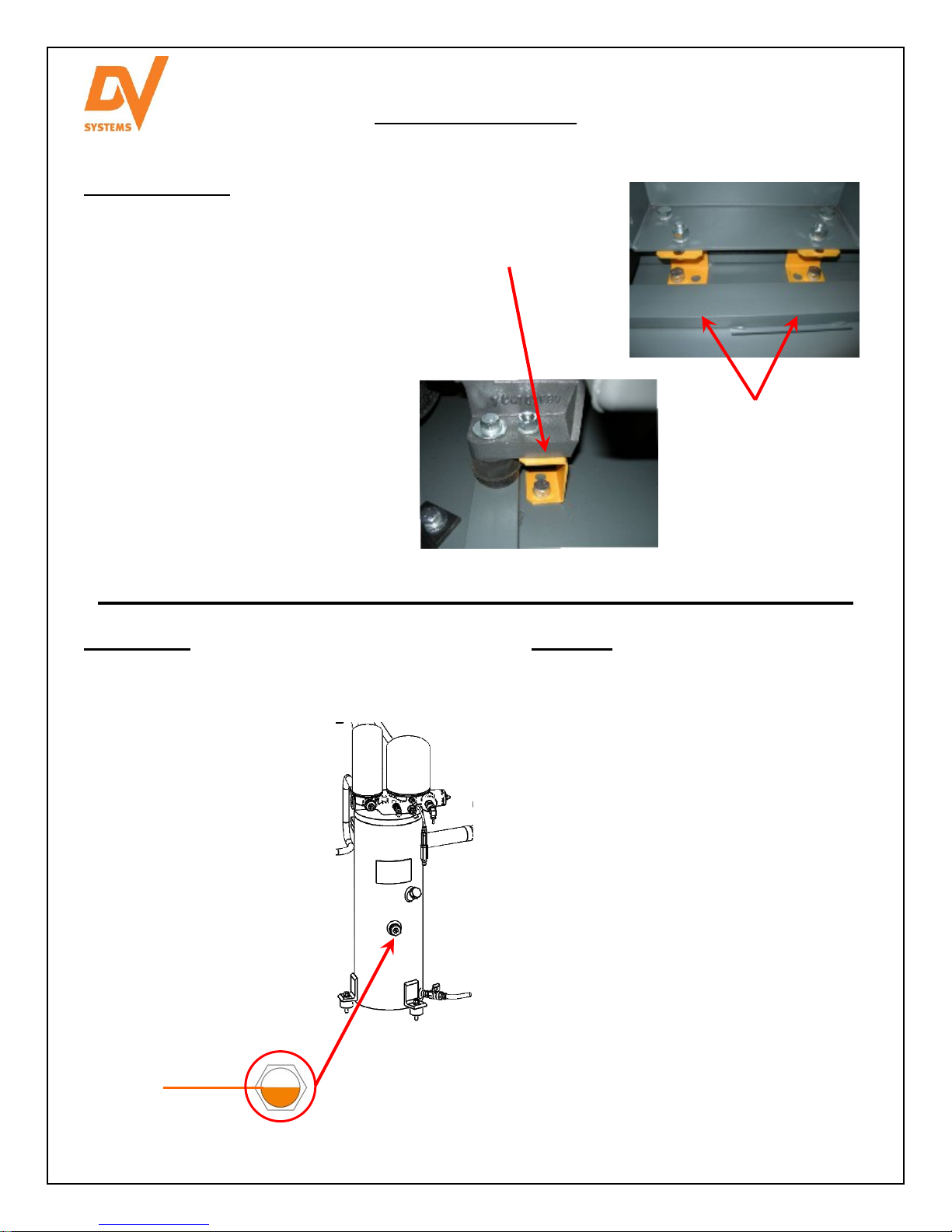
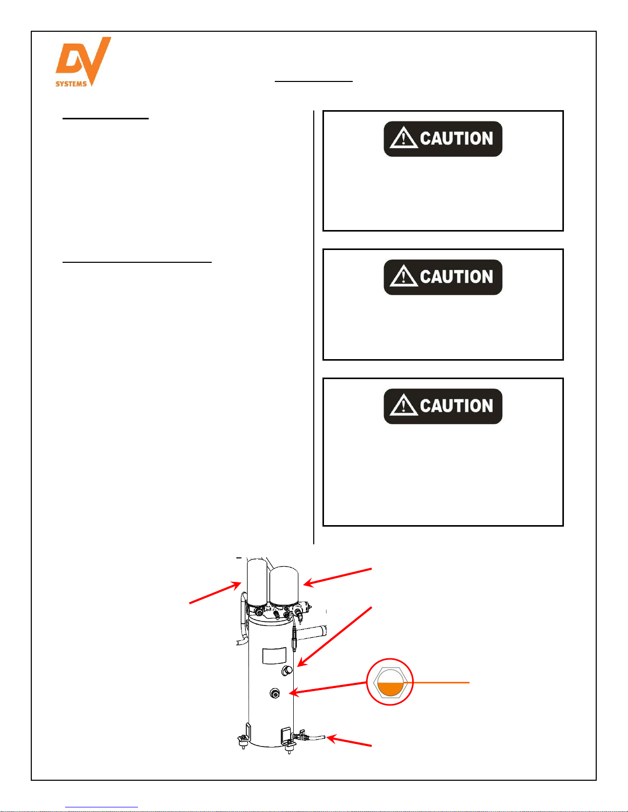
Fill the Oil Reservoir to the Metal Band on the
External Oil Level Gauge as shown below. Do not
under or overfill. See drawing below.
Use only DV Systems ‘DEV-3000’ Synthetic Oil,
available in both 1 US gallon (3.8 litre) jugs or 5 US
gallon (5 x 3.8 litre) pails. Any remaining oil may be
used for ‘top-ups’.‘
The ‘MK-G20-30-1’ Maintenance Kit includes:
(1) 5 US Gallon Oil (‘DEV-3000’)
(2) Oil Filter (’DSC-624’)
(1) Air/Oil Separator Filter (’DSC-001148’)
(2) Air Filter (’DSC-001961’)
(1) In Line Filter (‘DSC-612)
The ‘MK-G20-30-1’ Kit is appropriate for Units of
serial number ‘37162’ and higher. Use ‘MK-G20-30’
Kit for Units of serial number ‘37135’ and lower.
Do not attempt to operate the Unit without
first checking whether there is oil in the Oil
Reservoir. Add oil as required. Serious
damage may result from use, however
limited, without oil.
Use of improper oil may negatively affect
Compressor performance or shorten Unit life.
Resulting problems are not covered by the
DV Systems Inc. Air Compressor Warranty.
Condensation (water) may form in the Oil
Reservoir with the oil. If this occurs, as the
water will tend to settle on the bottom of the
Reservoir, drain the water from the Reservoir
until you notice oil draining. Top up the
Reservoir with new oil using only the DV
Systems ‘DEV-3000’ oil.
When running,
oil level will be
closer to bottom
Elbow
Oil Fill Port
Oil Drain Valve & Tube
Oil Filter DSC-624
Correct
Oil Level
Air/Oil Separator Filter
DSC-001148

G2030-II-C
Mar ‘17
- 11 -
Installation - Electrical
Ensure that all wiring, fusing, etc is done in a manner that meets with the appropriate codes and
regulations.
See the sales drawings and electrical schematic contained in this manual for information about Motor
nameplate amps, this is used to determine the appropriate Disconnect / Breaker and Wiring sizes.
Units equipped with Variable Speed Drives (VSDs) MUST use FAST-ACTING FUSES. Refer to the table
below for fuse sizes.
It is your responsibility to ensure that the Compressor
Unit is electrically connected in a safe and correct
manner. Any electrical work should be carried out
by a competent Electrician, and be done in such
a way that it meets all applicable Codes and
Regulations.
Ensure that a suitable Fused Disconnect or Breaker
(by others than DV Systems) is installed in the
electrical supply before the Compressor Unit.
Failure to observe any of the above precautions could result in severe personal injury or death,
and/or damage to the Unit.
General Information.
The sales drawing found at the back of this booklet
indicates the amp rating for the Unit. This information
is required in sizing a Disconnect, Fuses, and/or a
suitable Breaker. As well, an electrical schematic is
enclosed for reference.
Electrical wiring and conduit from the building supply,
through the Compressor Cabinet, and to the Switch
in the Compressor Control Panel, must be rated for
110°C (230°F) or higher.
Failure to correctly connect the
Compressor to your building's electrical
services may result in serious personal
injury or damage to the equipment.
Install all covers and panels before
applying power to the Unit.
Before servicing the Unit, ensure the
power source has been shut down and
locked off.
Read and understand the information
contained in this manual before installing
or operating the Unit.
Fusible Disconnects.
VSD Units:
HP Voltage Fuse
Type Fuse
Amp DV
Fuse
Part
No.
DV Disconnect
Kit (Disconnect +
Fuses)
25 200
DFJ/
HSJ
80 F080 FD-080
230 70 F070 FD-070
460 35 F035 FD-035
575 35 F035 FD-035
30 200
DFJ/
HSJ
110 F110 FD-110
230 80 F080 FD-080
460 40 F040 FD-040
575 35 F035 FD-035
Fixed Speed Units:
Use TIME-DELAY type fuse.
Max. Allowable Fuse =
1.75 x Motor Full Load Amp

G2030-II-C
Mar ‘17
- 12 -
Installation – Electrical (cont’d)
Wiring must be done in a manner that the full Motor nameplate voltage +/- 10% is available at the Motor terminals
during start-up. Contact your local Distributor or Service Centre if additional information is needed.
The Warranty that exists on the Electric Motor is that of the original manufacturer. In the event of a Motor failure,
contact your DV Systems Distributor or Service Centre for the location of the nearest authorized Motor Service
Centre.
It is critical that the Motor and Air End in the Rotary Screw Unit be turning
in the correct manner. Irreparable damage will be done if the Unit rotates
in the opposite direction.
This unit is equipped with Advanced Phase Detection which prevents unit
from rotating in the reverse direction. If the following error is visible on the
Screen and the Unit will not start, simply switch power leads L1 and L3.
Press the ‘Reset’ key on the Controller to reset the error message.
E:0090 Phase Sequence
Note: If the Motor is replaced or Motor Leads are re-wired, visually
check for correct Motor Rotation before installing the belts.
Conduit Opening
Do not attempt to operate the Unit without first checking whether there
is oil in the Oil Reservoir. Add oil as required. Serious damage may
result from use, however limited, without oil.
Electrical Connection.
The Electrician is to bring
power to the Unit through
the conduit hole located on
the Top Panel. The
Electrical Panel is
accessible by means of
opening the Unit Front RH
Door as shown at right.
Refer to the enclosed
sales drawing and
electrical schematic in
determining the correct
Disconnect / Breaker and
Wire size.
Motors.Motors.
Motor/Air End Rotation.
Bring power to L1, L2, L3

G2030-II-C
Mar ‘17
- 13 -
AC Motor Maintenance Instructions
Cleaning.
To ensure that the Motor operates at optimum temperatures and provides years of trouble-free service,
periodically clean the outside of the Motor Housing of any build-up of dust, etc. Though it is not anticipated that, if
installed correctly and in a suitable environment, there should be much build-up on the Motor, keeping the
Housing clean will allow the Motor to operate more efficiently.
Lubrication.
This is a ball bearing motor. The bearings have been lubricated at the factory. Motors that do not have re-grease
capability are factory lubricated for the normal life of the bearings.
Some motor designs use different bearings on each motor end. Noted below is a chart outlining the interval at
which the bearings of Motor should be lubricated, this based on the Bearing Sizes. This must be part of a regular
maintenance schedule.
Motor HP Interval
in Hours
Drive End * Opposite Drive End **
Weight of Grease Volume of Grease Weight of Grease
Ounces (Grams) In3(Teaspoon) Ounces (Grams)
20 / 25 /30 2,000 0.61 (17) 1.2 (3.9) 0.23 (7.2)
*Drive End would be the end that is connected to the driven device (air end).
**Opposite Drive End would be the end that is connected to the fan assembly.
The above chart is based on a standard environment in which the Motor is operating of 40°C (104°F). For other
conditions, please multiply the Hour Interval from the chart above by the factor as indicated below.
Severity of Duty Factor Environmental Conditions
Standard 1.0 40°C (104°F) , clean, little corrosion
Severe 0.5 50°C (122°F), moderate dirt, corrosion
Extreme 0.1 > 50°C (122°F), severe dirt, abrasive dust
Low Temperature 1.0 < 30°C (86°F)
Lubricant.
Baldor motors are pre-greased, normally with Mobil Polyrex EM. Equivalent and compatible greases are Texaco
Polystar, Chevron SRI #2, and Shell Dolium BRB.

G2030-II-C
Mar ‘17
- 14 -
Do not attempt to operate the Unit without first checking
whether there is oil in the Oil Reservoir. Add oil as required.
Serious damage may result from use, however limited, without
oil.
Initial Start-up
1) Remove the LH Front Access Panel, and ensure
that there is sufficient Oil in the Oil Reservoir.
Refer to the ‘Lubrication’ section (page 10) in this
manual for proper type and level of Oil.
2) Do a visual inspection of the Unit, and ensure
that all fasteners are sufficiently tightened. This
must be done, as some fasteners may become
loose in transit.
Start-up Procedures
Do not place any materials in close proximity
to the Compressor. Placing materials against
or close to the Unit will limit the cooling
required, and could lead to premature failure.
3) Place the Fused Disconnect / Breaker in the ‘On’
Position. Check that there is power to the
Controller.
4) During normal operation of the Unit, keep the
Access Panels closed at all times.
5) Ensure the Ball Valve on the Unit is closed, press
the ‘Start’ Button, and run the Unit up to
maximum pressure. The Unit will run up to
approx. 120 psi (8.3bar), at which point the Motor
will continue to run but not compress air.
6) Once the Unit reaches 120 psi (8.3bar), it will idle
for 8 or 10 minutes and shut off. For VSD units,
the unit will idle for 2 minutes and shut off.
7) Open the Ball Valve slightly and allow the air to
bleed from the Tank. Once the pressure reaches
approx 100 psi (6.9bar), the Unit will start and
begin to compress air after a short delay. For
VSD units, this pressure is 10 psi below the cut-
out pressure.
8) Measure the amp draw as the Unit reaches
maximum pressure.
9) Close the Ball Valve, allow the Unit to reach
maximum pressure, idle, and shut off. Once off,
check the various fittings etc inside the Cabinet to
ensure there are no internal leaks.
10) Once you are confident that there are no internal
leaks, the Unit will be ready for normal use.
11) Register the Unit to activate the Warranty by
completing the Warranty Registration Card by
Fax.
Shut off all power to the Compressor Unit
before attem
p
tin
g
an
y
re
p
air or maintenance.
Adjusting the settings of the Controller could adversely affect
the performance of the Unit. Only those individuals with
knowledge of the Unit should make any adjustments.
Unit Controls
Stop Button
Use this to shut
the Unit off. Allows
the Unit to idle and
then stop after
several seconds.
Emergency Stop Button
Do not use to normally stop the Unit. To be used to
stop the Unit in emergencies only. Normal use will
damage electrical controls and Shaft Seal.
Start Button
Allows the Unit to
start.

G2030-II-C
Mar ‘17
- 15 -
Preventative Maintenance Schedule
Noted on the following pages are general Maintenance guidelines based on average working conditions. Should
the Unit be worked under extreme conditions, please contact your DV Systems Distributor for further input. As
well, all maintenance/service work must be carried out by a qualified Technician.
The typical operating temperature of the Unit, this dependent on ambient temperatures, is between 70°C and
85°C (158°F and 185°F).
If the operating temperature of the Unit is too low (less than 70°C (158°F)):
condensation will build up in the system and mix with the oil, causing internal component problems in the
Unit
Change the ambient conditions to increase the operating temperature.
If the operating temperature of the Unit is too high (above 85°C (185°F)):
the oil will oxidize and lose it’s properties, this causing internal damage to components as well
to combat this, the oil must be changed more often than noted below.
When servicing the Air Compressor, shut off all
power to the Unit, and drain it of air pressure.
It is the responsibility of the Compressor owner
to ensure that a regular Maintenance Schedule
is followed.
Note: For Compressor Units used in an environment where the ambient temperature is above
32°C (90°F), the components marked with a ‘ # ’ (on the chart on the following page) must
be changed more frequently.
Regular Maintenance Items.
DV Systems offers a Maintenance Kit for your Unit,
namely:
MK-G20-30-1 20 to 30 HP ‘G Series’ Units
(Unit Serial # ‘37162’ and higher)
Each Kit consists of the following items, these
suitable for approximately 4000 hours of operation.
(1) DEV-3000 5 Gal. of Synthetic Oil
(2) DSC-624 Oil Filter
(1) DSC-001148 Air/Oil Separator Filter
(2) DSC-001961 Air Filter
(1) DSC-612 Inline Filter
For Units with a serial number of ‘37135’ and lower,
order Kit ‘MK-G20-30’.
Internal Access for Maintenance.
The internal components of the Unit are accessible
for servicing by way of removing the LH Front Panel
as shown.
The Belt access is by way of the RH Side Panel.

G2030-II-C
Mar ‘17
- 16 -
Preventative Maintenance Schedule (cont’d)
Maintenance Item: Daily Maintenance Interval (in 000’s of Hours)
2 4 6 8 10 12 14 16 18 20 22 24 26 28 30 32 34 36 38 40
Compressor Room
Temperature Inspect Ambient Temperature should be between 10°C and 40°C (50°F and 104°F)
Cleanliness Inspect
Air Compressor Unit
Check Oil Level Inspect
Replace Oil # (See Note b) (1) X X X X X
Replace Oil Filter # (2) X X X X X X X X X X
Replace Air / Oil Separator # (3) X X X X X
Replace Air Intake Filter # (4) X X X X X X X X X X X X X X X X X X X X
Check Belt Tension X X X X X X X X X X X X X X X
Replace Belts X X X X X
Replace Tank Relief Valve X X X
Replace Solenoid (5) X X X X X
Rebuild Intake Valve (6) X X X X X
Rebuild Thermo Valve (7) X X X
Rebuild Minimum Pressure Valve (8) X X X X X
Replace Scavenge Line Filter (9) X X X X X
Motor Bearing Lubrication Refer to Motor Manufacturer’s Recommendations on Page 13
Notes: a) For Compressor Units used in an environment where the ambient temperature is above 32°C (90°F),
or b) where the Unit temperature runs regularly above 80°C (175°F), the components marked with a
‘#’ must be changed twice as often (example: in 4000 hours instead of 8000), and not as noted
above.
b) The DV Systems Oil used in the Rotary Screw Units is rated as an 8000 hour Oil. A complete Oil
change must be done every 8000 hours of Unit operation, or every 12 months, whichever occurs first.
Please refer to the Warranty on Page 27 for further information.
c) If a component, during a regular inspection, has proven to be defective or unfit for regular operation, it
must be repaired or replaced.
Parts and Repair Kits based on the above chart are as follows:
(1) Oil: DEV-3000
(2) Oil Filter DSC-624
(3) Air / Oil Separator: DSC-001148
(4) Air Intake Filter DSC-001961 (for Units of s/n ‘37162’ and greater)
(4) Air Intake Filter DSC-001193 (for Units of s/n ‘37135’ and lower)
(5) Solenoid DSC-002052 (for Units of s/n ‘37162’ and greater)
(5) 2 Way Solenoid DSC-162 (for Units of s/n ‘37135’ and lower)
(5) 3 Way Solenoid DSC-140 (for Units of s/n ‘37135’ and lower)
(6) Intake Valve Repair Kit DSC-001999 (for Units of s/n ‘37162’ and greater)
(7) Thermo Valve Repair Kit: DSC-111-1
(8) Minimum Pressure Valve Kit: DSC-231
(9) Scavenge Line ‘In Line’ Filter DSC-612
VSD Ambient Filter DSC-001447
VSD Separation Foam DSC-002897
As noted previously, the ‘MK-G20-30-1’ Maintenance Kit (for Unit serial numbers ‘37162’ and higher) includes the
following items:
(1) DEV-3000 5 Gal. of Synthetic Oil
(2) DSC-624 Oil Filter
(1) DSC-001148 Air/Oil Separator Filter
(2) DSC-001961 Air Filter
(1) DSC-612 In-Line Filter

G2030-II-C
Mar ‘17
- 17 -
Common Compressor Faults
Common Faults.
Noted below are the most common Faults experienced.
‘CSC300’ Alarms.
There is an issue with the Unit, but it will still operate.
Code: Description: Most Common Items to Check:
A:0083 Motor phase imbalance Check supply voltage, fuses and cable
A:0119 Delivery Pressure High Solenoid not working, Intake Valve Orifice clogged, Transducer dirty or faulty, pressure changed
incorrectly, alternate external pressure source
A:0129 Delivery Temperature High Ambient temp high, Unit dirty, low oil level, no air flow through Unit, Temp Sensor defective
A:2816 Power Failure Occurred Press ‘Reset’ Button and restart Unit
A:4819 Routine Service Due Service Unit and reset Service Timer (Page ‘P16’ on Controller)
A:4809 Grease Service Due Service motor and reset Grease Service Timer (Page ‘P16’ on Controller)
‘CSC300’ Shutdown Errors.
There is an issue with the Unit, and the Unit will not operate until the Fault has been addressed.
Code: Description: Most Common Items to Check:
E:0010 Emergency Emergency stop switch is pressed
E:0070 Fan Motor Alarm Check electrical connections
E:0082 Motor Overload Motor drawing high amps, low voltage, high pressure settings, low oil level
E:0083 Motor phase Imbalance Check motor connections in the control panel and motor connection box
E:0090 Phase Sequence Rotation of Motor wrong, sequence order of supply cable incorrect
E:0091-
0093 Phase L1/L2/L3 Fault Check supply voltage, fuses and cable
E:0115 Delivery Pressure Sensor Fault Transducer not making good electrical contact, or defective
E:0119 Delivery Pressure High Solenoid Not working, Intake Valve Orifice clogged, Transducer dirty or faulty, pressure
changed incorrectly, alternate external pressure source
E:0125 Delivery Temp Sensor Fault Temperature Sensor not making good electrical contact, or defective
E:0129 Delivery Temperature High Ambient temp high, Unit dirty, low oil level, no air flow through Unit, Temp Sensor defective
E:0902 Anti-Rotation Rotation of Main Motor wrong, Solenoid Valve not relieving pressure
E:1902 Inverter Fault Variable frequency drive tripped. Check VFD screen for more info.

G2030-II-C
Mar ‘17
- 18 -
Variable Speed Drive
Your DV Systems ‘G Series’ Rotary Screw Compressor Unit may have been equipped with an optional ‘Variable
Speed Drive’, or ‘VSD’. A Compressor with an integral VSD can handle the constant loads for an extended period
of time (running at close to 100% duty cycle), but it can also run at slower speeds to accommodate lower air
demands at other times of the day.
Variable Speed Drives can reduce the overall energy costs associated with operating the Compressor Unit by
simply controlling the speed of the Motor and Air End to match consumption. As Rotary Screw Compressors
using the variable speed technology match the varying air demands and therefore have the ability to impact your
energy consumption, some energy providers have offered rebates when these Units are purchased. Consult your
local energy provider to determine if this applies.
Shown below is a ‘G Series’ Unit with a Variable Speed Drive.
VSD Interface
The VSD Controller Interface is shown at right. It
provides a means of operating, monitoring, and adjusting
the parameters of the Variable Speed Drive.
Please note that adjustments to the parameters of the
Variable Speed Drive should be made only by qualified
Technicians, or with the guidance of factory trained
personnel. Incorrect adjustments will affect the
performance of the Unit, and could result in damage to
the Drive.
Variable Speed Drive
‘CSC300’ Controller
Control Panel

G2030-II-C
Mar ‘17
- 19 -
Variable Speed Drive (cont’d)
Operating Screen
Typical Drive Status Indicators
The Status LED of the drive shows the status of the drive. It can show 5 different statuses.
Color of the LED light Status of the drive
Blinking slowly Ready
Green Run
Red Fault
Orange Alarm
Blinking fast Downloading software
The status of the drive is also indicated on its graphical display.
Status Fields: STOP / RUN and READY / NOT READY / FAULT
Control Place: PC / IO / KEYPAD / FIELDBUS. The default Control Place shall be ‘I/O’.
Location Field: the parameter ID number and the current location in the manual.
Default page of the graphical display is set to Multimonitor. On this Multimonitor page, 9 drive status items are
displayed.
Output Frequency: The output frequency to the motor
Frequency Reference: The frequency reference to motor control. It varies between min. and max. frequency.
Analogue Input 2: The input speed signal as a percentage of the used range.
Motor Current: The measured current at the motor leads
DC Link Voltage: The measured voltage at the drive capacitors.
Motor Speed: The actual speed of the motor.
Unit Temperature: The heatsink temperature of the VFD.
Motor Temperature: The calculated motor temperature in percentage of the nominal working temperature.
Slot A DIN 1, 2, 3: The status of the digital input 1~ 3.
Status Fields Control Place
Location Field
Status LED

G2030-II-C
Mar ‘17
- 20 -
Fault
Code
1 Over-current. Current too high in Motor Cable. Check loading.
Check Motor.
Check Cables.
2 Over-voltage. The DC link voltage has exceeded the limits.
- too short a deceleration time Make deceleration time longer.
- high voltage spikes in supply Check input voltage.
3 Earth Fault. Insulation failure in Motor or wiring. Check Motor wires and Motor.
7 Saturation. - component failure Cannot be reset. SWITCH OFF THE POWER and DO
NOT RESTART THE DRIVE. Contact distributor.
9 Undervoltage The DC link voltage is lower than the limits. Check input voltage.
10 Input phase - supply voltage malfuntion Check input voltage.
- a defective fuse or malfunction in the supply cables
13 AC drive undertemperature Heatsink temperature is below -10°C.
14 AC drive overtemperature Heatsink temperature is over 90°C. Check the amount and flow of cooling air.
Overtemperature warning is issued when the heatsink Check the heatsink for dust.
temperature exceeds 85°C. Check the ambient temperature.
Ensure the switching frequency is not too high
in relation to ambient temperature and motor
load
15 Motor stall. Motor stall protection has tripped. Check Motor and load.
16 Motor over-temperature. Motor is overloaded. Decrease motor load.
17 Motor under-load. Motor under-load temperature has tripped. Check load.
32 Fan cooling. - Fan speed does not match the speed reference. Check drive fan. Contact Distributor.
- Fan life time (50,000 h) is reached.
41 IGBT temperature The calculated IGBT temperature is too high. Check loading.
Check ambient temperature and amount of cooling air.
Check parameter settings.
46 Real Time Clock The voltage of the RTC battery is low. Replace the battery.
50 AI low fault Current at the analogue input is less than 4 mA. Check the current loop circuitry.
- control cable is broken or loose.
- signal source has failed.
52 Keypad communication The data connection between the control keypad and the Check keypad connection and possible keypad cable.
fault. frequency converter is broken.
54 Slot fault. Defective option board or slot. Check board and slot.
Contact the nearest Distributor.
Fault Possible Causes: Corrective Measures:
Variable Speed Drive (cont’d)
Common VSD Fault Codes
Noted below are the most common fault codes that may appear on the VSD. For a more thorough list, please
check the manual which deals exclusively with the Vacon Variable Speed Drive and which accompanied the Unit.
Other manuals for G20
1
This manual suits for next models
8
Table of contents
Other DV Systems Air Compressor manuals

DV Systems
DV Systems G20 Manual

DV Systems
DV Systems IS5-4060-03 Manual

DV Systems
DV Systems IS Series Manual

DV Systems
DV Systems H40, H50, H50VSD-C User manual

DV Systems
DV Systems A5 (T) Manual

DV Systems
DV Systems HDI Manual

DV Systems
DV Systems C10 Installation manual

DV Systems
DV Systems D20 Installation and operation manual

DV Systems
DV Systems IS13-5530 Setup guide