DVDO iScan HD+ User manual

BY ANCHOR BAY TECHNOLOGIES
1
Product Guide
English Version
How to install, set up, and use your new DVDO product
High Resolution
Video Scaling Engine

TABLE OF CONTENTS
Table of Contents 1
Introduction 2
Installation and Set-Up 3
System Requirements and Compatibility 3
Video Inputs
Digital Audio Inputs
iScan Rear View Connections 4
Signal Flow Diagram 4
Typical System Configuration 5
Output Signal Connections 6
Power Supply Input 6
Display Input Connectors 6
HD15 (VGA-type) Connector
Component (YPbPr ) Input with RCA Jacks
DVI Digital Video Input
Displays and Controls 7
Initial Set-Up 7
Analog Component Output (YPbPr)
Analog RGB Output
DVI Output
Power/Standby Control 8
▲, ▼, and Enter/Exit Controls 8
Output Setup 8
Formats 9
Input Aspect Ratio Control 10
Picture Control 11
Saved Settings for Individual Inputs 11
Audio Operation 11
From the Front Panel
From the On-Screen Display (OSD)
Digital Audio Outputs
Input Adjust Control 12
Configuration Control 13
Customizing the Output Video Timing
for your Display 14
Automation Controls 14
Remote Control Operation 15
On-Screen Display (OSD) 15
Output Setup 15
Configuration 15
Picture Control 15
Input Adjust 15
Menu 15
Zoom 15
Pan 15
Aspect Ratio Buttons 15
Input Select Buttons 16
Power Button 16
Info 16
Curtain 16
Test Patterns 16
Technical Specifications 18
Safety Information 19
Warranty 20
Acknowledgements 20

INTRODUCTION
Input
Select
Input
Aspect
Ratio Picture
ControlInput
AdjustConfiguration
Adjust
Enter/Exit
Analog
/Digital
Format/Resolution
Aspect Ratio
Sync Type
Colorspace
Framelock
Display Profile
High Resolution Video Scaling Engine by Anchor Bay Technologies
Power
Output
Setup On/Remote
Standby
Thank you for purchasing the iScan HD+High Resolution Video
Scaling Engine, featuring video-processing technology as created
by the Anchor Bay Technologies team. This product delivers a
level of video quality among the very highest available today.
We are especially pleased to bring you ABT’s new High Definition
Precision Video Scaling™technology. This technology enables
precision upconversion of Standard and High Definition (480i,
480p, 576i, 576p, 720p or 1080i)) video sources and content to
the native or optimum resolution of your display, delivering
best-in-class front-of-screen performance. Available output reso-
lutions span from 480p all the way to 1080p, including the
standard HDTV resolutions of 720p and 1080i. In addition to our
own video scaling technology, new to the DVDO product line, the
iScan HD also offers a host of other innovative features.
Among these are:
䊳
flexible Digital Audio switching
䊳
precision audio/video time-delay synchronization
䊳
improved timebase correction
䊳
fully programmable framerate conversion
䊳
input and output aspect ratio controls
䊳
flexible zoom and pan controls
䊳
SDI input capability
(with the DVDO SDI Video Input Module)
The Technical Specifications section at the end of this
Product Guide summarizes the key features and performance
of the iScan HD+.
This Product Guide will help you set up your new iScan HD+,
and will also give you information on how to match it to your
display, as well as how to connect it to and use it with the
rest of the components in your system.
Should you have any questions during the setup or operation
of this DVDO product, you should first contact your Authorized
DVDO Reseller for assistance. You can also contact Anchor Bay
Technologies directly for assistance:
Toll-Free (in the USA) 1.866.423.DVDO
Email Help@DVDO.com
Website www.DVDO.com
The carton of your iScan HD+should contain the following:
䊳
iScan HD+High Resolution Video Scaling Engine
䊳
Universal 6V@5A AC to DC power converter
䊳
US power cord (international customers - please
consult your local Authorized DVDO Reseller)
䊳
Remote control
䊳
iScan HD+Product Guide
The iScan HD+uses a 15-pin HD15 VGA-type connector and a
DVI connector to provide video output signals. You will need to
purchase an output cable to connect one of these outputs to
your projector, HD-compatible TV, Plasma display panel, or
other display device. Different displays have different input
connectors, so please check your display specifications to ensure
compatibility. Even though the HD15 connector is commonly
used on personal computers for RGB video, the iScan HD+is
capable of outputting either RGB or YPbPr (Component) video
formats from this connector. This is explained in detail in the
Output Setup section of this Product Guide.
Both input and output cables can be supplied by your
Authorized DVDO Reseller. To find your nearest Authorized DVDO
Reseller, go to www.dvdo.com/res/index.html
You can also find a wide selection of cables on our website at
www.dvdo.com/pro/pro_acc.html
2

System Requirements and Compatibility
The iScan HD+is designed to drive displays that can accept
an ATSC Digital Television or VESA-standard PC video signal in
analog RGB or YPbPr (Component) video format, or digital
DVI format. Such displays include:
䊳
Projectors – DLP, LCD, CRT, D-ILA
䊳
HDTVs
䊳
Progressive scan and multimedia TVs
䊳
Plasma TVs
䊳
Computer monitors
If you are not sure if your display is compatible with the iScan
HD+, please contact your local Authorized DVDO Reseller. Anchor
Bay Technologies also maintains display compatibility information
on the DVDO website at www.dvdo.com/faq/faq_compat.html
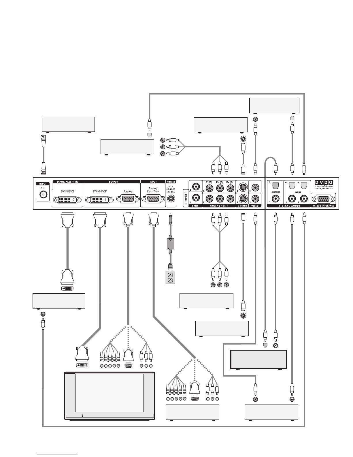
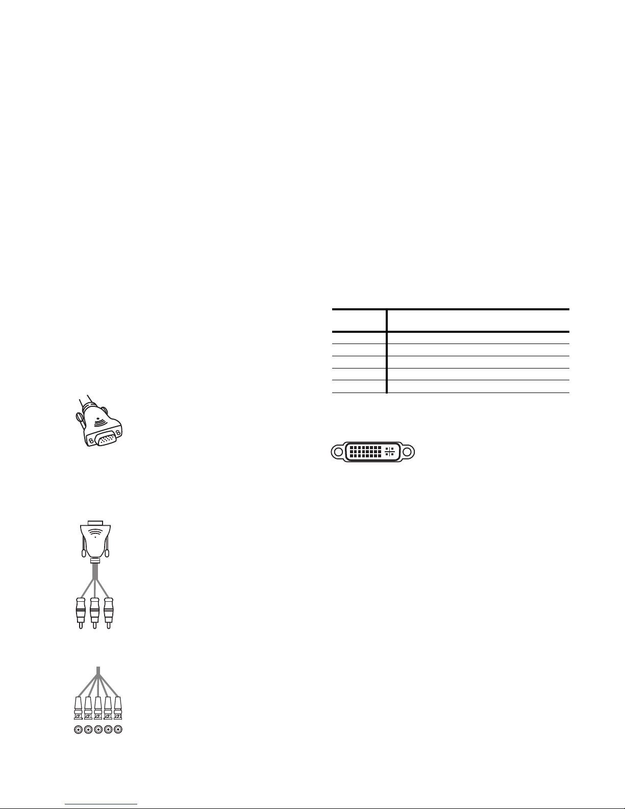
Input Signal Connections
Video Inputs
The iScan HD+has nine (9) video inputs. The inputs and the
formats they support are:
䊳
Video 1 (NTSC, PAL, and SECAM)
䊳
Video 2 (NTSC, PAL, and SECAM)
䊳
S-Video 1 (NTSC, PAL, and SECAM)
䊳
S-Video 2 (NTSC, PAL, and SECAM)
䊳
Component/RGBS 1 (NTSC, PAL, SECAM,
480p, 576p, 720p, 1080i)
䊳
Component/RGBS 2 (NTSC, PAL, SECAM,
480p, 576p, 720p, 1080i)
䊳
DVI/HDCP (480p, 576p, 720p, 1080i)
䊳
Analog Passthru (for use with sources for which no video
processing is desired, such as native HDTV or PC formats)
䊳
SDI (NTSC, PAL and SECAM – SMPTE 259M-C compliant)
High Definition signal formats (720p, 1080i) on the Component
inputs are automatically passed through to the output.
Video 1 and Video 2 inputs are also referred to as Composite
video inputs. In general, Composite video delivers the lowest
final image quality while Component video delivers the best
image quality. There is a large improvement in image quality
between Composite and S-Video, but the difference between
S-Video and Component video is less noticeable.
If you have a DVD player, satellite receiver or digital cable box
with DVI/HDMI output, it is recommended that you connect the
output to the iScan HD+’s DVI input. The iScan HD+will process
both Standard and High Definition sources on it’s DVI input
including 480p,576p,720p and 1080i. In addition, the iScan
HD+will also process HDCP protected content on its DVI input.
However, the iScan HD+will only output HDCP protected con-
tent on its DVI output with HDCP enabled. The iScan HD+will
not output HDCP protected signal on its analog output.
For sources with analog outputs, it is recommended that you use
the Component video inputs to connect to your iScan HD+. VCRs
generally have the lowest image quality, and therefore will not
be as affected by the lower quality of the composite video signal
connection. An exception is S-VHS VCRs, which feature an
S-Video output of higher quality than conventional VHS VCRs.
The Analog Passthru input is used for analog video sources
that do not require processing, such as HDTV satellite broad-
casts, video sources that are already in progressive format
or HD formats, or personal computer video output. This input
allows you to pass these signals through the iScan HD+without
any video processing.
Digital Audio Inputs
There are a total of four (4) Digital Audio inputs:
䊳
Digital Audio 1 (coaxial)
䊳
Digital Audio 2 (coaxial)
䊳
Digital Audio 3 (optical)
䊳
Digital Audio 4 (optical)
The iScan HD+accepts Digital Audio sourced from DVD players,
DBS receivers, digital cable set-top boxes, or other digital audio
devices. There are four (4) inputs; two each of Coaxial and
Optical transmission interface types. These inputs are compatible
with most consumer Digital Audio formats, including CD-Audio
(44.1kHz/16 bit linear pulsecode modulation), Dolby Digital, or
DTS. Generally, the Digital Audio inputs are compatible with any
format with a sampling frequency between 44 kHz and 96 kHz,
and with a data word structure between 16 and 24 bits in length.
3
INSTALLATION AND SET-UP

4
Installation and Set-Up (continued)
Analog video output
DVI-D digital video output
Digital AudioOut 2 (Optical)
Digital AudioOut 1(Coaxial)
Component Video1(YPbPr)
Component Video2 (YPbPr)
S-Video1
S-Video2
Video1(Composite)
Video2 (Composite)
Analog Pass-Thru
DVI
Digital Audio1(Coaxial)
Digital Audio4(Optical)
Digital Audio2 (Coaxial)
Analog Audio(L/R)
iScan HD+
Video
Processor/
Scaler
DVD PlayerorotherComponentvideo
source withDigital Audio output
SDI*
Digital Audio3(Optical)
DVD PlayerorotherSDI*video
source withDigital Audio output
Projector,HD-ReadyTV,
Plasmadisplaypanel,
computermonitor,
orotherSD/HDcapable
displaydevice
DVD PlayerorotherComponentvideo
source withDigital Audio output
DBSReceiver,Game Consoleorother
S-Videosource withDigital Audio output
DVD Playerorother
S-Videosource
VCRorother
Compositevideo source
LaserdiscPlayerorother
Compositevideo source
HD-DBSReceiver,PC,orother
HighDefinition video source
HD-DBSReceiver,PC,orother
HighDefinition video source
AVPreamplifier/ProcessororAVReceiver
Digital Audio Inputs
Analog
Audio
Inputs
or
*SDIVideo Input Module required
Signal Flow Diagram
The following diagram shows a typical way to use the iScan HD+
in a system. This figure depicts a system where the iScan HD+is
used as the primary video switcher or “hub”. The iScan HD+is
usually placed between the display device and any video sources
and acts as the source switch for the display.
*
Component 2
(YPbPr or RGB)
Component 1
(YPbPr or RGB)
Power
Composite
Video 2
Composite
Video 1
Digital
Audio Out
2 (optical)
Digital
Audio Out
1(coaxial)
Digital Audio
Inputs4, 3
(optical)
Digital Audio
Inputs1,2
(coaxial)
Serial Port
S-Video 2
S-Video 1
Sync2
Sync1Analog
Output
Analog
Passthru
DVIOutputDVIInputSDIInput*
iScan Rear View Connections
The following figure shows the input and output connector com-
plement on the rear panel of the iScan HD+. There are a total of
nine (9) Video inputs, two Video outputs, four (4) Digital Audio
inputs, and two Digital Audio outputs. Also shown are the DC
Power input and the RS-232 Serial Port.

5
Installation and Set-Up (continued)
Typical System Configuration
The iScan HD+is usually placed between the display device and
any video sources and acts as the source switch for the display.
Shown in this connection diagram are nine audio/video
sources, four of which have digital audio outputs along
with analog video outputs.
DVI-D
DVI-D
DVI-D
Progressively Scanned TV or Projector
Universal
Power Adaptor
ACMains
(100-240 VAC
50/60 Hz)
Component
Video Cable
S-Video Cable
Composite Video Cable
S-Video Cable
Composite Video Cable
Digital Audio Cable (Optical)
Digital Audio Cable (Coaxial)
Component Video Source
(480i,480p,720p,or 1080i)
YPbPr
VCRor Other
S-Video Source
Component Video Source
(480i,480p,720p,or 1080i)
Set-Top Boxor Other
DVI source
HDSatellite TVTuner,PC,or
Progressive-Scan DVD Player
5xBNC
3xRCA
or
or
Video Game or Other
Composite Video Source
Set-Top Boxor Other
S-Video Source
Video Game or Other
Composite Video Source
DVI-D
Audio/Video Preamplifier/
Processor or AV Receiver
Component
Video Cable
Digital Audio Cable (Optical)
YPbPr
Digital Audio Cable (Optical)
HDVideo
DVI-D or DVI-I Interface Cable
DVI-D or DVI-I
Interface Cable
HDVideo
5xBNC
3xRCA
or
or
HD15 HD15
HD15
HD15
Rear Viewof
iScan HD+
*
BNCCable
DVD Player or Other
SDI*source
*SDI Video Input Module required
Digital Audio Cable (Coaxial)

Output Signal Connections
There are two output connectors on the back of the iScan HD+:
1) 15-pin HD15 Analog Output (VGA-type)
2) DVI Digital Video Output (with HDCP)
Use the 15-pin HD15 ouput of the iScan HD+to interface
to displays with a Component or VGA input. Use the DVI output
of the iScan HD+to interface to displays equipped with the
DVI interface.
Power Supply Input
The iScan HD+comes with a 6V@5A AC to DC converter power
supply, which accepts 100-240 VAC at 50/60Hz. Connect this to
the ‘DC In’ port on the back of the iScan HD+. IMPORTANT: Use
only the power supply that came with your iScan HD+, or a
replacement procured directly from Anchor Bay Technologies.
Display Input Connectors
There are a number of different connectors used on displays,
such as RCA, 15-pin HD15 (VGA-type), BNC and DVI connectors.
HD15 (VGA-type) Connector
The VGA cable/connector is commonly used
in PC applications and should be readily
available in any computer or electronics store.
Select a well-shielded high-quality cable to
reduce reflections and other degrading effects on
the video signal. Most multimedia TVs/displays with progressive
scan capability will have an input of this type and should
accept both YUV and RGB color formats.
Component (YPbPr ) Input with RCA Jacks
Most displays with Component video inputs
will have three RCA jacks for YPbPr video signal
connections. Use the DVDO Precision HD15 to
3-RCA Component Video Cable (ABT part number
11-2001-01) to connect to these displays.
You can find it on our website at
www.dvdo.com/pro/pro_acc.html
Connect the three signal lines to the correspond-
ing color RCA jacks on your display.
BNC Connectors
Many displays such as home theater projectors
have five BNC connectors instead of an HD15
connector. For these displays, use an adapter
cable to convert from VGA to the BNC connectors
used on the display. These adapter cables are
readily available through most home theater
retailers and have a VGA connector on one end and BNC
connectors on the other. The BNC end of the cable will usually
have five connectors (labeled R, G, B, Hsync, and Vsync),
although not all will necessarily be needed for every display.
Please refer to your display’s specifications to determine which
input signals it requires. If your display device accepts
Component video (YPbPr), then you will not need the H and V
lines since these sync signals are actually part of the informa-
tion in the ‘Y’ signal. If your display device requires RGBS, then
this is Composite Sync, which is sent on the H (white/gray)
line. Displays that require RGBHV will require all 5 BNC connec-
tors. Hsync is sent on the white/gray wire, and Vsync is sent on
the yellow/black wire.
Below is a table showing the signal mappings for each wire of
the BNC cable.
DVI Digital Video Input
The DVI digital video connector is
used on many newer digital TVs and
is similar in functionality to the
analog VGA connector except that the video signal is transmit-
ted digitally from the iScan HD+to the display device. This
provides the highest possible quality video image from the iScan
HD+to the display. Many displays also support the High-band-
width Digital Content Protection (HDCP) specification across
the DVI interface. Displays with a DVI/HDCP input will show
protected content from the iScan HD+DVI output.
Once you have the iScan HD+connected to your home theater
system, there are several configuration parameters that you may
adjust to output the proper signal format for your display device
and optimize the image to your personal preferences.
6
Installation and Set-Up (continued)
Input Type
Wire Color RGB/HV RGBS YPbPr YUV/HS
(Component)
Red R (Red) R (Red) Pr U
Green G (Green) G (Green) Y Y
Blue B (Blue) B (Blue) Pb V
White or Gray H sync Composite sync No Connect H sync
Yellow or Black V sync No Connect No Connect V sync

Initial Set-Up
Once you have installed the iScan HD+into your system, it must
be properly configured for the display device being driven. The
iScan HD+is shipped from the factory with the following preset
default settings:
䊳
Input Select is set to AUTO, to automatically detect
an active input in a pre-configured priority.
䊳
The Analog Video output is selected.
䊳
The output format is set to ATSC (DTV) 480p, with YPbPr
colorspace and bilevel sync on the luma signal.
Use either the remote control or the front panel controls to
perform the initial setup of the iScan’s output. The front panel
buttons are used to perform the initial setup described below.
There are three ways to connect the iScan HD+output to a
display device. They are Analog Component, Analog RGB,
and DVI output.
Analog Component Output (YPbPr)
Typically, an HD15 (VGA-type) to 3-RCA connector cable is
needed for this configuration.
1. Connect the VGA end to the iScan’s Analog Video output.
2. Connect the 3 RCA connectors into the display device’s
Component Video input.
3. Select the corresponding input on the display device.
You should get a picture. Now you are ready to set up your
display further with the remote control unit using the iScan
HD+’s on-screen display (OSD).
Note: the iScan HD+features a set of predefined formats that
you can choose from. These formats include colorspace and sync
signal type as shown in the Format table on page 9. If you
choose a format that requires RGB colorspace and separate
Hsync and Vsync, you need to manually change the colorspace
to YPbPr and sync type to bi-level or tri-level sync. Once this is
done, future format selections will always use the same color-
space and sync type that you reset the unit to.
Analog RGB Output
Typically either a VGA to VGA, a VGA to 5-BNC, or a VGA to
5-RCA cable is needed for this configuration.
1. Connect the HD15 (VGA) end to the iScan’s Analog output.
2. Connect the other end of cable to the display device’s
RGB input jacks.
3. Change the sync type of the iScan HD+from bi-level sync to
separate HSync and VSync. There are four separate sync
selections: positive Hsync and Vsync (H+V+), positive Hsync
negative Vsync (H+V-), negative Hsync positive Vsync (H-
V+) and negative Hsync and Vsync (H-V-). Most formats
default to negative Hsync and Vsync. Refer to the Preset
Format table on page 9 for more details.
䊳
Push the Output Setup button until Sync Type is
selected and the front panel display (FPD) shows ‘SYNC’.
䊳
Press the ▼button to see the sync type ‘BI’
(for bi-level sync).
䊳
Press the ▼button to go to the next sync type.
䊳
Repeat this step to select the desired sync type.
䊳
Push the Output Setup button to exit the menu.
4. Change the colorspace from Component YPbPr to RGB
䊳
Push the Output Setup button again. The FPD shows
‘COLR’ for colorspace selection.
䊳
Press the ▼button. The FPD shows ‘YUV’, which is the
current colorspace (Component YPbPr).
䊳
Press ▼button again to select the ‘RGB’ colorspace.
䊳
Push the Output Setup button to exit the menu.
You have now configured the iScan HD+to output 480p in RGB
colorspace, with separate Hsync and Vsync signals. Set up your
display further with the remote control unit using the iScan
HD+’s on-screen display (OSD).
Note: The actions above result in the iScan HD+always using
RGB for colorspace and separate Hsync and Vsync signals regard-
less of format selection.
DVI Output
1. Connect the DVI cable from the DVI output of your iScan
HD+to the display device.
2. Push the Output Setup button once.
3. The FPD will show ‘A/D’ for analog or digital video output
choices.
4. Push the ▼button once. The FPD will now display ‘ANLG’
for Analog Video output.
5. Push ▼button again. The FPD will now show ‘DVIV’ for DVI
with Video levels.
6. You should now see a picture on your display device.
7
DISPLAYS AND CONTROLS
Front Panel Display (FPD)
Down Up
Output Setup Indicators
On/Standby
Input
Select
Input
Aspect
Ratio Picture
ControlInput
AdjustConfiguration
Adjust
Enter/Exit
Analog
/Digital
Format/Resolution
Aspect Ratio
Sync Type
Colorspace
Framelock
Display Profile
High Resolution Video Scaling Engine by Anchor Bay Technologies
Power
Output
Setup On/Remote
Standby
Front of Unit

You have now configured the iScan HD+to output 480p on DVI.
Note: Since the DVI video format is defined as RGB with
separate Hsync and Vsync signals, there is no need to modify
colorspace or sync type when using the DVI output. The format
selection is always set to RGB with separate Hsync and Vsync.
Power/Standby Control
Pushing the Power button toggles the system between two states:
active and standby. There is a tricolor LED that is next to the
Power button. In Standbymode, the LED is illuminated red.
When the system is active, the LED color indicates:
blue (the system is processing the input signal); green (the
system is passing through the signal without processing).
▲, ▼, and Enter/Exit Controls
These buttons allow you to navigate the menus and submenus.
Their functions are dependent on the specific function selected.
Output Setup
The Output Setup settings allow you to configure the output of
the iScan HD+to match the requirements of the specific type
and model of display device being driven.
Pushing the Output Setup button once shows the current output
control function. You can cycle through the functions by pushing
this button repeatedly. There is an LED corresponding to each
function. This helps you to set up the output without an image
on the display. The table below shows the available functions.
The FPD (front panel display) and the OSD (on-screen display)
will turn on when the Output Setup button is pressed. The
Output Setup indicators, FPD, and OSD will turn off automatical-
ly after 30 seconds.
8
Output Setup FPD shows Description
Analog or
Digital Output
A/D Pushing the ▼button shows the current output type. Pushing the ▼button again selects the next item on the list
shown below. You can also use the ▲button to cycle through the output types.
VGA Analog Output (VGA-type HD15)
DVIV DVI output for displays that require video signal levels.
DVIP DVI output for displays that require PC signal levels.
Output Format FMT Pushing the ▼shows the current output format. Pushing the ▼button again shows the next item on the list shown
below. The format is not selected until the Enter/Exit button is pressed. Pressing the Enter/Exit button again selects
the output timing controls, discussed in the Output Timing section.
Output
Aspect Ratio
O_AR Sets the display output aspect ratio. Press the ▲or ▼button first to show the current aspect ratio. Press the same
button again to move to the next aspect ratio. Currently three aspect ratios are supported: 16:9, 4:3 and 5:4.
More aspect ratio options will be supported in future software releases.
Sync Type SYNC Sets the synchronization signal type of the output format. Press the ▲or ▼button first to show the current sync type.
Press the same button again to move to the next sync type. Currently seven sync types are supported:
BI bi-level sync on green/luma (in RGB colorspace, sync is also present on red and blue signals)
TRI tri-level sync on green/luma (in RGB colorspace, sync is also present on red and blue signals)
CSYN Composite Sync (on the Hsync pin of the HD15 output connector)
H+V+ Positive Hsync and Positive Vsync H+V-Positive Hsync and Negative Vsync
H-V+ Negative Hsync and Positive Vsync H-V-Negative Hsync and Negative Vsync
Color Space COLR Sets the colorspace of the output format. Press the ▲or ▼first to show the current colorspace. Press the same
button again to select the alternate colorspace. Two colorspaces are supported: YPbPr (default) and RGB.
Frame Rate
Conversion
FRC Enables frame rate conversion. There are two sets of controls, one for 50Hz input sources and one for 60Hz input
sources. For 50Hz sources, if the original source material is progressive at 25Hz (uses 2:2 pulldown), the output frame
rate can be source locked at either 50Hz or 75Hz. The 75Hz setting will repeat each of the original 25Hz frames 3
times. You can also set the output frame rate to a specific value (unlocked mode). For 60Hz sources, if the original
source material is progressive at 24Hz (uses 3:2 pulldown), the output frame can be source locked to either 48Hz,
60Hz or 72Hz. The 48Hz setting will repeat each original 24Hz frame 2 times, while the 72Hz setting will repeat each
frame 3 times. As with 50Hz sources, you can also set the output frame rate to a specific value (unlocked mode).
Press the ▲or ▼button once to see the current input rate. Press the same button again to switch input rate.
50 - > 50Hz input sources 60 - > 60Hz input sources
Press the Enter/Exit button to select the input frame rate and change the output frame rate settings. Select the
desired output frame rate setting by using the ▲or ▼button.
For 50 Hz input sources, the available settings are:
50 L source locked 50Hz
75 L source locked 75Hz
UNLK unlocked
If UNLK is chosen, press the Enter/Exit button again to specify the desired output frame rate.
Use the ▲or ▼button to increase or decrease the frame rate.
Press the Output Select button again to exit the menu and complete the output frame rate conversion setting.
Display Profile DISP currently not available
Displays and Controls (continued)
Output
Setup
Menu
For 60 Hz input sources, the available settings are:
48 L source locked 48Hz
60 L source locked 60Hz
72 L source locked 72Hz
UNLK unlocked
Note: the Sync Type function
is disabled with DVI output,
because the DVI standard
requires separate Hsync and
Vsync

Formats
For DVI output, the Sync type is always separate Hsync and
Vsync, and the colorspace is always RGB. For analog output, the
factory default format is 480p as shown in the table. Once you
override the sync and colorspace selection, future format selec-
tions will not affect the sync type and colorspace. The predefined
formats 720p, 1080i and 1080p are compliant with the CEA-861B
specification for DVI output. Each format has two timing modes,
one for 50Hz inputs and the other for 60Hz inputs.
Input Select Control
The Input Select control enables you to select one of the nine
(9) inputs of the iScan HD+. When this button is first pressed,
the front panel display (FPD) shows the current selected input.
When this button is pressed again, it selects the next input on
the list. When you’ve reached the last input, pressing the button
again selects the first input on the list and the process repeats.
You can also cycle through the inputs by pushing this button
once and then pressing the ▼or ▲arrow buttons.
The table below shows the list of inputs in the order that they
are cycled through using the Input Select button. The location
of the connectors is shown on page 4.
The Input Select indicator (LED), the front panel display (FPD)
and the on-screen display (OSD) will turn on when the button
is pressed. The indicator will turn green if the selected input is
active and red if it is not active. The Input Select LED, FPD and
OSD will turn off automatically after 30 seconds. If the input is
not active, the LED will remain red.
9
Input
Select
Control
Displays and Controls (continued)
Horizontal
Resolution Vertical
Resolution Scan
Type* FPD
shows Sync
Signal
Line(s)
Sync
Signal
Type
Color-
space
720 480 P480P YBi-level YPbPr
1920 540 P540P YTri-level YPbPr
720 576 P576P YBi-level YPbPr
1280 720 P72P5 YTri-level YPbPr
1280 720 P72P6 YTri-level YPbPr
1920 1080 I18I5 YTri-level YPbPr
1920 1080 I18I6 YTri-level YPbPr
1920 1080 P18P5 YTri-level YPbPr
1920 1080 P18P6 YTri-level YPbPr
640 480 PVGA H-V- -RGB
800 600 PSVGA H+V+-RGB
1024 768 PXGAH-V- -RGB
1280 1024 PSXGA H-V- -RGB
852 480 PPLA1 H-V- -RGB
852 576 PPLA2 H-V- -RGB
1366 768 PPLA3 H-V- -RGB
1280 768 PPLA4 H-V- -RGB
1024 1024 PPLA5 H-V- -RGB
1024 852 PPLA6 H-V- -RGB
1024 576 PDLP1 H-V- -RGB
848 600 PDLP2 H-V- -RGB
1365 1024 PDIL1 H-V- -RGB
1400 1050 PDIL2 H-V- -RGB
1400 788 PDIL3 H-V- -RGB
960 540 PLCD1 H-V- -RGB
1280 960 PQUA1 H-V- -RGB
1440 960 PQUA2 H-V- -RGB
1440 1152 PQUA3 H-V- -RGB
*P = progressive; I = interlace
Preset Formats and Characteristics for Analog Video Output
Input FPD shows Description
Video 1 VID1 Composite Video 1
Video 2 VID2 Composite Video 2
S-Video 1 SVD1 S-Video 1
S-Video 2 SVD2 S-Video 2
Component 1 /
RGBS 1
COM1 Component Video 1 - This input accepts either a YPbPr or RGBS signal. The input is configured for YPbPr by default,
and switches to RGB when a connector is plugged into the Sync 1 input. This input will accept 480i, 480p, 576i and
576p formats. All other formats will be passed through to the analog output unprocessed.
Component 2 /
RGBS 2
COM2 Component Video 2 - This input accepts either a YPbPr or RGBS signal. The input is configured for YPbPr by default,
and switches to RGB when a connector is plugged into the Sync 2 input. This input will accept 480i, 480p, 576i and
576p formats. All other formats will be passed through to the analog output unprocessed.
Analog Passthru PASS Analog Passthru is selected. This signal is passed through to the Analog Output unprocessed.
DVI DVI DVI Input - The DVI input accepts 480p, 576p, 720p and 1080i formats. If the content is copy-protected by HDCP,
the iScan HD+will output the processed signal on the DVI output with HDCP or if the analog output is selected, the
iScan HD+will output blue screen. Non HDCP signals will be output on either the DVI output or analog output.
Other input formats are passed through to the DVI output unprocessed.
SDI* SDI SDI Input. – This input accepts either a 480i or 576i signal from an SDI source.*
*SDI Video Input Module required.
Automatic
Input Selection
AUTO Automatic active input selection - Automatically selects an input from among all currently active inputs based on an
internal priority list. The factory default list is shown below from highest to lowest priority. You can assign different
priorities to the iScan HD+’s video inputs using the Configuration control then selecting AutoSource (IPSL).
Note: The DVI input and Analog
Passthru functionality is depen-
dent on which output is selected.
1- Component / RGBS 1
2- Component / RGBS 2
3- S-Video 1
4- S-Video 2
5- Video 1
6- Video 2
7- DVI
8- SDI*
9- Analog Passthru

Input Aspect Ratio Control
The Input Aspect Ratio control selects the aspect ratio for the
current input signal. The iScan HD+will automatically convert
from the selected input aspect ratio to the selected output
aspect ratio.
Pushing the Input Aspect Ratio button once shows the current
input aspect ratio control function. You can cycle through the
available functions by pushing this button repeatedly.
For the Input AR function, pushing the ▲or ▼ button once
shows the current setting. Pushing either of these buttons again
will cycle through the available aspect ratios. Push the
Enter/Exit button to exit the menu and go back to the Input
Aspect Ratio selection.
For the Zoom, Pan and Borders functions, pushing the ▲or ▼
button selects the two control settings available: horizontal and
vertical. Push the Enter/Exit button to adjust each setting.
䊳
Push ▲and ▼to increase or decrease the setting.
䊳
Push Enter/Exit again to exit this mode.
Note: The Zoom and Pan function are applied to the input
signal, not the output. This is an important consideration,
especially for the Pan function. For example: If a full frame
image is not zoomed more than 100%, there is nothing to pan.
However, if part of the image is not on the screen, then the
Pan function will work.
The table shows the available Input Aspect Ratio controls.
The Input Aspect Ratio LED, the FPD (front panel display) and
the OSD (on-screen display) will all illuminate when the button
is pressed. The LED, FPD, and OSD will turn off automatically
after 30 seconds.
10
Displays and Controls (continued)
Input A.R.
Controls FPD
shows Description
Input AR INAR Selects the aspect ratio of the input signal:
4/3: 4:3 aspect ratio (full-frame)
LBX: 16:9 image aspect ratio in 4:3 frame
16/9: 16:9 aspect ratio (full-frame)
PRST The Preset function is set to 16:9 input aspect ratio by default. It stores the latest custom aspect ratio settings that you
have defined. This is unique to each input. A custom aspect ratio is defined as a standard aspect ratio (16:9, LBX or 4:3)
that has been modified with the Zoom, Pan and Borders controls. If no custom aspect ratio is defined, it will remain 16:9.
Zoom ZOOM The Zoom function zooms in on or magnifies the image on your display. The minimum zoom is 100%, (no zooming) while the
maximum zoom is 150% (zoom magnification factor of 1.5X).
HOR Horizontal Zoom control. Pushing the Enter/Exit button shows the current Zoom setting.
Pushing ▲and ▼button increases or decreases the zooming factor.
VERT Vertical Zoom control. Pushing the Enter/Exit button shows the current Zoom setting.
Pushing ▲and ▼button increases or decreases the zooming factor.
Pan PAN The Pan function allows the image to be shifted up, down, left and right. Note that the Pan function can only be used after
the image has been zoomed to any value greater than 100%.
HOR Horizontal Pan control. Pushing the Enter/Exit button shows the current Pan setting. Pushing the ▲button pans to the
right. Pushing the ▼button pans to the left.
VERT Vertical Pan control. Pushing the Enter/Exit button shows the current Pan setting. Pushing the Enter/Exit button shows the
current Pan setting. Pushing the ▲button pans up. Pushing the ▼button pans the image down.
Borders BORD The Borders function allows you to add horizontal and/or vertical borders around the image. These borders will obscure part
of the input image. Certain input-to-output aspect ratios already result in left/right or top/bottom border being added. This
control allows the system-generated borders to be extended, or for borders to be added when none exist. As the borders are
adjusted (see below) the iScan will temporarily increase the gray level of the borders so that they are visible during the
adjustment process. The level will return to normal after the adjustment has ceased.
HOR Horizontal Border control. Pushing the ▲button moves the left and right borders towards the middle of the image, increasing
the border width and cutting off the sides of the input image. Pushing the ▼button moves the left and right borders away
from the image and decreases their width. If there are system-generated left/right borders already present (e.g, when the
input aspect ratio is 4:3 and the output aspect ratio is 16:9), the border width cannot be decreased beyond the base width
created by the aspect ratio conversion.
VERT Vertical Border control. Pushing the ▲button moves the top and bottom borders towards the middle of the image,
increasing the border height and cutting off the sides of the input image. Pushing the ▼button moves the top and
bottom borders away from the image and decreases their height. If there are system-generated top/bottom borders already
present (e.g, when the input aspect ratio is 16:9 and the output aspect ratio is 4:3), the border height cannot be
decreased beyond the base height created by the aspect ratio conversion.
Input
Aspect
Ratio
Control
Menu
㛮

Picture Control
Pushing the Picture Control button once shows the current
picture control function. You can cycle through the available
functions by pushing this button repeatedly.
For each function, pushing the ▲or ▼button once shows the
current setting. Pushing either of these buttons again will
increase or decrease the setting. Push the Enter/Exit button to
exit the menu and go back to the picture control selection.
The table below shows the available Picture Controls.
The Picture Control LED, the FPD (front panel display) and the
OSD (on-screen display) will turn on when the button is pressed.
The LED, FPD, and OSD will turn off automatically after 30 seconds.
Saved Settings for Individual Inputs
The iScan HD+saves the settings listed below for each
individual video input and format, where applicable. There are
two independent sets of saved settings for each input: one for
a 50Hz input such as PAL and SECAM, the other for a 60Hz input
such as NTSC. There are no saved settings for the Analog
Passthru and DVI Passthru input.
Picture Control
Brightness Contrast
Saturation Hue
Sharpness Y/C Delay
Chroma Filter
Input Aspect Ratio
11
Displays and Controls (continued)
Picture Controls FPD shows Description
Brightness BRT Adjusts the brightness of the selected input signal. Default setting is 0 (midrange).
Contrast CNT Adjusts the contrast of the selected input signal. Default setting is 0 (midrange).
Saturation SAT Adjusts the color saturation setting of the selected input signal. Default setting is 0 (midrange).
Hue HUE Adjusts the hue (tint) of the selected input signal. Default setting is 0 (midrange).
Note: This control has no effect on Component or PAL format input signals.
Sharpness SHRP Adjusts the sharpness of the selected input signal. Default setting is 0 (midrange).
Note: This control has no effect on Component Video input signals.
Sharpness
(Component)
SHRC Adjusts the sharpness of the selected input signal. Default is Off.
Note: This control has no effect on Composite video or S-Video input signals.
Y/C Delay YC D Adjusts the Y/C differential Delay of the selected input signal. Default is 0.
Chroma Filter
(Auto CUE-C)
CUEC Auto CUE-C. This feature removes chroma upsampling errors (CUE) found in some video sources which have been
MPEG encoded and then improperly decoded. There are three available settings:
OFF: No chroma filtering. Use this setting if the source does not have a CUE problem.
ON: Chroma filtering is always on. Use this setting if the source is known to have a CUE problem.
AUTO: Automatic chroma error detection and correction. Use this setting if it is not known if a source has a
CUE problem. This setting is also recommended for all digital sources which use MPEG2 decoders (DVD players,
digital satellite receivers, etc.) as it will also detect and correct chroma errors created by all sources of this
type when the source is encoded as interlaced (also sometimes called Interlaced Chroma Problem, or ICP).
Picture
Control
Menu
Audio Operation
The iScan HD+features an audio delay function to exactly match
the video delay incurred by the video processing. The iScan HD+
accepts four digital audio inputs: two coaxial (Audio 1, 2) and
two optical (Audio 3 and 4) inputs. The location of the audio
inputs are shown on back panel diagrams earlier in this docu-
ment. The factory default audio assignment is:
Digital Audio 1 (coaxial) : Component 1
Digital Audio 2 (coaxial) : S-Video 1
Digital Audio 3 (optical) : S-Video 2
Digital Audio 4 (optical) : Component 2
You can assign a Digital Audio input to each Video input in the
following manner:
From the Front Panel
1. Select a video input as described in Input Select Control,
page 9.
2. Use the Input Adjust button to select the Digital Audio
input assignment function (ASEL) as described above. Push
the ▲or ▼button to select the audio input.
3. Select the next video input. Repeat step 2.
From the On-Screen Display (OSD)
using the Remote Control
1. Select a video input on the remote control.
2. Select Audio Input 1, 2, 3, 4 or Off from the ‘Input
Adjust/Audio Input’ menu.
3. Select the next video input. Repeat step 2.
Digital Audio Outputs
There are two digital audio outputs, one coaxial and one optical.
Both are active at the same time, with the selected input Digital
Audio stream.

12
Input Adjust FPD shows Description
Border level BLEV The Border level can be also be adjusted to prevent burn-in with some displays. The border level setting is global i.e.
there is only one border level setting for the system. To adjust border level, push the ▼or ▲button. The current level is
shown. The default value is ‘0’. Pushing the ▼or ▲button decreases or increases the border level.
Overscan SCAN The Overscan function scales the input image proportionally in both vertical and horizontal dimensions by the user-speci-
fied overscan factor. The purpose of Overscan is to remove unwanted image portions around the perimeter of the image.
The default overscan value is 0, which means 100% of the input image is shown. The maximum overscan value is 20
which means the input image scaled up by 120%. To adjust the overscan level, first push the ▼or ▲button. The current
level is shown. Pushing the ▼or ▲button then decreases or increases the amount of overscan. The Overscan value is
applied to all input aspect ratios and is independent of the Zoom value.
Line Offset LINE The image can be adjusted vertically when an SDI input is selected using the Line Offset function. This function can be
set independently for both NTSC and PAL/SECAM input formats.
DVI Input DVII The DVI Input control function allows you to configure the DVI Input in ‘Auto’ mode or in ‘Passthru’-only mode. Pushing the
▲or ▼button shows the current setting. Pushing the same button again switches to the other setting.
AUTO: The DVI input will process all 480p, 720p and 1080i incoming signals with or without HDCP. If any other
signal is input into the DVI input, the system will switch into Passthru mode.
DPTH: The DVI input will only function as a pass-thru input. All input signals will be passed through to the DVI
output. In this mode the OSD from the system won't be displayed although you can navigate through the menu
using the front panel controls.
VCR Mode VCR VCR Mode decouples the output timing completely from the input timing to ensure a stable output from the iScan HD+for
VCR playback especially during trick-play modes (play forward, play reverse, still/pause). There are 3 modes:
ON: Output timing is decoupled from the input timing regardless of Frame Rate settings.
OFF: Output timing is dependent on Frame Rate settings.
AUTO: Turns on VCR Mode if a VCR source is detected.
Film Mode FILM Film Mode allows you to control the film mode operation of the iScan HD+. Most of the time the automatic film mode detec-
tion is preferred. However there are some cases where the detection needs to be turned off, or biased towards film. There are
three modes - OFF, BIAS and AUTO.
OFF: Turns off film detection in the deinterlacer. All video sources are treated as original video
BIAS: The Film Bias mode may improve film mode detection in some cases. For example, it may improve the detection
of PAL/SECAM film sources.
AUTO: Source adaptive deinterlacing is on.
Auto Input
Priority
Selection
AIPS The Auto Input Priority Selection function assigns different priorities to the video input’s automatic active video selec-
tion mode (AUTO in Input Select menu). First select the video input, then change the priority of that input.
1- Press the ▼button.
2- The first video input VID1 is shown.
3- Press the Enter/Exit button to view the current priority of the selected input.
4- Press the ▲or ▼button to change the priority of the selected input.
5- Press the Enter/Exit button again to complete the priority assignment.
6- Repeat Steps 1 through 5 to select the next video input and adjust the priority setting.
Audio Input ASEL The Audio Input function assigns a Digital Audio input to the currently selected Video input. To assign the audio input to
another video input, push the ▼button. The front panel display (FPD) will show the current setting.
Pushing the ▼button again will assign the next audio input. The five settings are:
AUD 1 (Coax) AUD 2 (Coax) AUD 3 (Optical) AUD 4 (Optical) OFF
(When this control is set to OFF, the Digital Audio outputs are disabled when the corresponding video input is selected.)
AV Lip Sync AVLS iScan HD+automatically delays the input audio to match the video processing delay. You can choose to increase or
decrease the audio delay by changing this setting. Pushing the ▲or ▼button first displays the current additional bias
delay setting (default 0). Use the ▲or ▼button to increase or decrease the delay in milliseconds.
Note: the total audio delay cannot be less than zero - i.e., the iScan cannot have negative audio delay. If you choose to
decrease the automatic delay setting by a certain amount - this value could be changed by the iScan in situations where the
iScan's calculated delay plus the specified additional delay will result in a value less than zero.
Input
Adjustment
Menu
Input Adjust Control
Pushing the Input Adjust button once shows the current input
adjustment function. You can cycle through the available func-
tions by pushing this button repeatedly.
The currently available input adjust functions are
- Border level - VCR mode - AV Lip Sync
- Overscan - Film mode - Line Offset
- Auto Priority - DVI input control - Audio Input
Other functions will be added in future software releases.
The table below shows the available Input Adjustment controls.
The Input Adjust LED, the FPD (front panel display) and the OSD
(on-screen display) will turn on when the button is pressed. The
LED, FPD, OSD will turn off automatically after 30 seconds.
Displays and Controls (continued)

Configuration Control
The Configuration control provides access to additional impor-
tant control functions. Pushing the Configuration button once
shows the currently selected function. You can cycle through the
functions by pushing this button repeatedly.
The table below shows selections that can be controlled.
The Configuration LED, the FPD (front panel display) and the OSD
(on-screen display) will turn on when the button is pressed. The
LED, FPD, and OSD will turn off automatically after 30 seconds.
13
Displays and Controls (continued)
Configuration FPD shows Description
Test Patterns TEST This menu allows you to select the 27 different test patterns available in the iScan HD+. Push the ▲or ▼button to
select one of the test patterns. Push the Test Patterns button on the remote control to activate the selected test pat-
tern. Push the button again to deactivate the test pattern. Refer to the Test Patterns section of this guide for more
details on using the Test Patterns feature of the iScan HD+
Auto Standby STBYThe default setting is OFF, which means iScan HD+will always be in Active mode regardless of the activity state of the
selected input. If Auto Standby is ON, iScan HD+will go into Standby mode 30 seconds after the selected input becomes
inactive. To see the current setting, first press ▲or ▼. Then press the same button again to change the setting.
HDCP Mode HDCP There are 3 HDCP modes:
OFF: HDCP is disabled at the iScan HD+'s DVI input. Some sources will turn off HDCP in this case and the iScan
HD+will drive a non-HDCP DVI display or an analog display.
ON: The iScan HD+will continuously look for a HDCP display device on its DVI output.
AUTO: The iScan HD+will look for a HDCP display device for a limited time, after which it will output blue screen
to a non-HDCP display.
Power LED PLED Allows you to configure the behavior of the Power LED.
OFF: Turns the Power LED off at all times
ON: Turns the Powe LED on. LED turns blue when the system is processing the an input signal. LED turns red in
standby mode. LED turns green in pass-through mode.
AUTO: LED turns off after approximately 30 seconds without user interaction.
User Mode USRM You have limited access to the output timing controls in ‘Normal’ mode. In ‘Advanced’ user mode, you have access
to the complete set of output timing controls. See the section entitled “Customizing the Output Video Timing for your
Display”. Push the ▼button to see the current setting. The FPD will display either ‘NORM’ for normal or ‘ADV’ for
advanced user level. Pushing the ▼button again selects the alternate mode.
Serial Port Rate R232 The serial port is used by the automation system controllers to control the iScan HD+. Refer to the Automation Control
section of this guide for more information. The serial port baud rate defaults to 19200 bps but can be changed using
the ▲or ▼button. The supported baud rates are:
1.2K 1200 bps 4.8K 4800 bps 14.4K 14400 bps 38.4K 38400 bps
2.4K 2400 bps 9.6K 9600 bps 19.2K 19200 bps 57.6K 57600 bps
Factory
Default
FCTD Allows you to reset system settings to the factory default. First press either the ▲or ▼button. The FPD will show ‘NO’.
Then press the same button to switch to ‘YES’. Confirm this selection by pressing the Enter/Exit button.
The default factory settings are:
Input Selection : Auto
Input Aspect Ratio : 16:9
Picture Controls : midrange (0)
Sharpness (Component) : Off
Chroma Filter (CUEC) : Off
Output Aspect Ratio : 16:9
Output Resolution : 480P
Sync : Sync on Y
Output Color Space : YPbPr
Output Type : Analog
Auto Standby : Off
Frame Rate : 60Hz input - 1:1 source-locked output
50Hz input - unlocked at 59.94 Hz
User Mode : Normal
Video Input Priority Settings :
Digital Audio Input Assignment :
Software
Update
SWUP You can upgrade your iScan HD+firmware using this command. First press the ▲or ▼button. The FPD will show ‘NO’.
Then press the same button to switch to ‘YES’. Confirm this selection by pressing the Enter/Exit button. Care must
be taken before performing a firmware upgrade. Make sure you really want to do this. Once the ‘YES’ selection is
confirmed, the FPD will show ‘LOAD’. If you change your mind, you can wait for about 5 minutes for the command
to be cancelled or you can power cycle the system by unplugging the DC Power input jack.
The About Box INFO This shows information about the system including Input Status, Output Status and System Version number.
Press the ▲or ▼button to activate.
Configuration
Control Menu
1– Component 1
2– Component 2
3– S-Video 1
4– S-Video 2
5– Video 1
6– Video 2
7– DVI
8– SDI
9– Analog Passthru
Component 1 - Audio 1
Component 2 - Audio 4
S-Video 1 - Audio 2
S-Video 2 - Audio 3
Video 1 - Off
Video 2 - Off
DVI - Off
SDI - Off
Analog Passthru - Off

Customizing the Output Video Timing
for your Display
The iScan HD+allows you to customize its output timing for the
specific requirements of the display. Full output timing adjust-
ment should be done only if you are very familiar with advanced
display setup. Caution: if you are not familiar with display
setup, you should not make certain output adjustments as
the wrong setup can result in loss of a picture, and in
extreme cases could potentially damage your display.
The iScan HD+features two modes of operation: ‘Normal’ and
‘Advanced’. In ‘Normal’ mode, you have access to two output tim-
ing parameters: ‘Horizontal Shift’ and ‘Vertical Shift’. Other out-
put timing parameters are disabled. In Advanced mode, you
have access to the complete set of output timing parameters.
The first step in setting up custom timing for your display is to
choose a starting point from the list of predefined formats. The
format closest to the desired output timing or resolution should
be chosen. The next step is to modify this predefined timing
format to match your display’s requirements. Once you have
changed the output timing parameters, the iScan HD+assigns
the new timing information to a custom format called “User”.
A description of each of the output timing parameters that can
be adjusted is shown in the Output Timing table that follows.
Adjusting the Output Timing
To adjust the output timing of the iScan HD+,
䊳
Push the Output Setup button until the Format/Resolution
LED lights up and the FPD (front panel display) shows “FMT”.
䊳
Push the ▼button to see the current output format.
䊳
Push the Enter/Exit button to see the first control, which is
‘Horizontal shift’.
Repeatedly pushing the ▼button will cycle through the avail-
able timing controls in the order as shown in the table, starting
with ‘Horizontal Shift’.
These parameters can be adjusted (with the exception of the
total number of pixels per line and lines per frame) from the
front panel controls as follows:
䊳
Push the Enter/Exit button to see the current format.
䊳
Push the ▼or ▲button to adjust the setting.
䊳
Push the Enter/Exit button again to complete the adjustment.
Automation Controls
Automation system controllers can control the iScan HD+
through the serial (RS-232) port using the protocol specified
in the iScan HD Automation Protocol document. This document
can be downloaded directly from DVDO’s website at
www.dvdo.com/faq/faq_pro_man.html
The Serial Port baud rate defaults to 19200 bps but can be
changed in the Configuration menu as specified earlier in the
Configuration Control section.
The iScan HD can also be controlled with direct commands
through the infrared (IR) interface using the protocol specified in
the Direct IR Controls document. This document is also available
from DVDO's website at www.dvdo.com/faq/faq_pro_man.html
14
Output Timing Controls Description
Horizontal Shift This setting shifts the image left or right in 1-pixel steps. Increasing the setting shifts the image to the left, while decreas-
ing the setting shifts the image to the right. The width of the active video portion of the horizontal line is preserved during
shifting, but the front and back porch timing values are modified. Increasing the horizontal shift value decreases the hori-
zontal back porch time and increases the front porch time by the shift value (and vice versa for decreasing the shift value).
Horizontal Size (Advanced mode only) This setting adjusts the horizontal resolution of the image in 1-pixel steps.
Horizontal Front Porch (Advanced mode only) This setting adjusts the horizontal front porch in 1-pixel steps.
Horizontal Sync (Advanced mode only) This setting adjusts the horizontal sync width in 1-pixel steps.
Horizontal Back Porch (Advanced mode only) This setting adjusts the horizontal back porch in 1-pixel steps.
Horizontal Total (Advanced mode only) This parameter cannot be changed. It displays the total number of pixels per line, which is the total
of the front porch, sync width, back porch, and active video.
Special Note For
Horizontal Adjustments
The sum of the horizontal sync width and the horizontal back porch must be an even number when the iScan HD+'s analog
output is used. If this sum is odd, then the Pb and Pr chroma components are reversed, causing the image color to be
incorrect. There are 3 horizontal timing adjustments that can affect this sum: Shift, Sync, and Back Porch.
Vertical Shift This setting shifts the image up or down in 1-line steps. Increasing the setting shifts the image up, while decreasing it
shifts the image down. The height of the active video portion of the frame is preserved during shifting, but the front and
back porch values are modified. Increasing the vertical shift value decreases the vertical back porch and increases the front
porch by the shift value (and vice versa for decreasing the shift value).
Vertical Size (Advanced mode only) This setting adjusts the vertical resolution of the image in 1-line steps.
Vertical Front Porch (Advanced mode only) This setting adjusts the vertical front porch in 1-line steps.
Vertical Sync (Advanced mode only) This setting adjusts the vertical front sync in 1-line steps.
Vertical Back Porch (Advanced mode only) This setting adjusts the vertical back porch in 1-line steps.
Vertical Total This parameter cannot be changed. It displays the total number of lines per frame, which is the total of the front porch,
sync width, back porch, and active video.
Output
Timing
Control
Menu
Displays and Controls (continued)

The iScan HD+Infrared Remote Control (IRC) offers more func-
tionality and convenience than the front panel control buttons.
Unlike the front panel controls, the remote control has a com-
plete set of navigation buttons: Left, Right, Up, Down, Enter,
and Exit. The remote control buttons have slightly different
behavior than the corresponding front panel buttons. The remote
control buttons and their control actions are described below.
On-Screen Display (OSD)
The on-screen display (OSD) of the iScan HD+is self-explanatory.
It is activated from the remote control or from the front panel.
We have designed the OSD’s behavior to be consistent with the
front panel and commands issued from the remote control.
Output Setup
This button has the same functionality as the Output Setup
button on the front panel. (See Output Setup, page 8.) Use the
navigation control buttons to select the desired function and
adjust the settings.
Configuration
The Config button has the same functionality as the
Configuration button on the front panel. (See page 13.)
It activates the OSD. Use the navigation control buttons to
select the desired function and adjust the settings.
Picture Control
This button has the same functionality as the Picture Control
button on the front panel. (See Picture Control, page 11.) Use
the navigation control buttons to select the desired function
and adjust the settings.
Input Adjust
This button has the same functionality as the Input Adjust but-
ton on the front panel. (See Input Adjust Control, page 12.) Use
the navigation control buttons to select the desired function
and adjust the settings.
Menu
This button activates the top level OSD menu, which lists the
controls in the table below.
Use the navigation control buttons to select the desired function
and adjust the settings.
Zoom
This button puts the iScan HD+into Zoom mode. Unlike the
Zoom function activated from the front panel, you can use the
navigation buttons to zoom up, down, left and right. There is
currently no OSD for this mode.
Pan
This button puts the iScan HD+into Pan mode. Unlike the Pan
function activated from the front panel, you can use the naviga-
tion buttons to pan up, down and left and right. There is cur-
rently no OSD for this mode.
Aspect Ratio Buttons
There are four buttons to directly set the input aspect ratios:
䊳
4:3
䊳
LBX (Letterbox)
䊳
16:9
䊳
PRESET
The Preset button acts just like the PRST function described earlier
(page 10). It defaults to 16:9 and stores a custom aspect ratio that
you’ve defined using Zoom, Pan and Borders functions.
15
Controls FPD shows
Input Select INPT
Input Aspect Ratio I_AR
Input Adjust IADJ
Picture Control PICT
Configuration CNFG
Output Setup OSET
REMOTE CONTROL OPERATION
INPUT SELECT
CURTAIN
POWER
INPUT
ADJUST
CONFIG
PICTURE
CONTROL
OUTPUT
SETUP
MENU EXIT
123
456
789
0
INPUT
ASPECT RATIO
4:316:9LBXPRESET
AUTO
COMP2S-VID2VID2SDI
COMP1S-VID1VID1PASSTHRU
ENTER
DVI
ZOOMPAN
INFOTEST
PATTERNS
Navigation
buttons
Power
Numeric
buttons
Pan
Aspect Ratio
Inputs
Information Test Patterns
Curtain
Output Setup
Configuration
Picture Control
Input
Adjustment
Menu
Zoom

Test Pattern FPD shows Description
Frame &
Geometry
FGEO This test pattern contains two specific test features. The first is a 1-pixel wide box around the very outside of the image.
This is used to determine when the entire iScan output image is visible on the display. The arrows along the middle of
each edge provide an indication of the amount of overscan (if any). The blue boxes in the center of each quadrant are
used for measuring display geometry. The rectangle in the center of the gray boxes should appear square on a 4:3 aspect
ratio display, the next large rectangle should appear square on a 16:9 display, the next on a 1.85:1 display, and the largest
rectangle should be square on a 2.35:1 display. The blue boxes are also used as an indication that the horizontal position-
ing of the output image is correct. Due to the iScan HD+'s 4:2:2 internal processing, with a custom output resolution it is
possible to cause the Cb & Cr components to become reversed. If the blue boxes are displayed as red instead of blue, then
the Cb & Cr components are reversed. This can be corrected by ensuring that there is an even number of pixels in the sum
of the horizontal sync and horizontal back porch.
Brightness
& Contrast
BRCN This test pattern is composed of 4 quarter-screen blocks. Two of the blocks have a background level of standard black,
and the other two blocks have a background level of standard white. Embedded in the black blocks are 3 bars. One is 4
IRE below black, one is 1 IRE above black, and the third is 2 IRE above black. Embedded in the white blocks are 3 bars.
One is 1 IRE above white, one is 1 IRE below white, and the third is 2 IRE below white. This test pattern is useful for
setting display black and white levels. The bottom 2 blocks differ slightly from these levels. For the bottom 2 blocks, the
blacker-then-black bar is at the lowest possible luma level, and the whiter-than-white bar is at the highest possible luma
level. Also included in the pattern are 2 needle pulses, which can be used to check CRT voltage regulation as well as the
presence of scan velocity modulation.
1-Pixel
Checkerboard
CHCK This test pattern consists of a 1-pixel black and white checkerboard. The test pattern alternates black and white pixels in
both the vertical and the horizontal direction. This pattern is useful for exactly matching the iScan’s output resolution to
that of the display to achieve 1:1 pixel mapping and bypass any scaling operation which may be incorporated in the display.
1-Pixel
Vertical
Lines
VLIN This test pattern consists of an alternating series of 1-pixel black and white vertical lines. The test pattern alternates black
and white pixels in only the horizontal direction. This pattern is useful for exactly matching the iScan’s output resolution to
that of the display in order to achieve 1:1 pixel mapping and bypass any scaling operation which may be incorporated in
the display. Its use is similar to that of the 1-pixel checkerboard, but it operates only in the horizontal direction.
16
Input Select Buttons
There are ten direct input selection buttons, as shown below.
Power Button
This button puts the unit into activeor standbymode. It has
the same functionality as the Power button on the front panel.
Info
This activates the OSD to put up the Information box
(described earlier).
Curtain
This button gradually puts up a black ‘curtain’ over the image.
It may help prevent burn-in in plasma TVs or CRT based displays.
Pushing this button again removes the curtain.
Test Patterns
This feature generates test patterns as an aid in matching
the output of the iScan HD+to your display. The test patterns
replace the normal output of the iScan and are rendered at the
iScan’s output resolution. There are 27 test patterns currently
available. The test patterns are activated via the Test Patterns
button on the remote control. Pushing the button activates
the currently selected test pattern. Pushing it again turns the
currently selected test pattern off, and reverts the unit to
normal operation.
To select a test pattern to send to your display, use the
Configuration button on the remote control or on the front
panel of your iScan HD+. The first entry under the menu that is
displayed on the OSD is Test Patterns. From this menu, you can
select one of the 27 test patterns that you wish to display. After
you activate the desired test pattern using the Test Pattern but-
ton on the remote control, you can change the currently selected
test pattern without returning to the Configuration menu. You
can do this by using the “1” and “3” keys on the numeric keypad
of the remote control. The “1” key will move you backward in the
test pattern list, and the “3” key will move you forward in the
list. See the Test Pattern listing below for descriptions of each.
Remote Control Operation (continued)
VID1 Video 1 (Composite)
VID2 Video 2 (Composite)
S-VID1 S-Video 1
S-VID2 S-Video 2
COMP1 Component 1/RGB 1
COMP2 Component 2/RGB 2
PASSTHRU Analog Passthru
DVI DVI
AUTO Automatic active input detection and selection
SDI SDI (SDI Video Input Module required)
Test
Patterns
Menu
(Test Patterns Menu table continues on the next page)

17
Test Pattern FPD shows Description
1-Pixel
Horizontal
Lines
HLIN This test pattern consists of an alternating series of 1-pixel black and white horizontal lines. The test pattern alternates
black and white pixels in only the vertical direction. This pattern is useful for exactly matching the iScan’s output resolu-
tion to that of the display to achieve 1:1 pixel mapping and bypass any scaling operation which may be incorporated in
the display. Its use is similar to that of the 1-pixel checkerboard, but it operates only in the vertical direction.
This pattern is blacked-out for the 1080i output resolution due to the severe flicker it causes on some displays.
Frame Rate JUDD The Frame Rate Conversion test pattern consists of a vertical bar which moves slowly back and forth across the screen. The
bar’s motion is updated once in each output frame period of the iScan, and it moves a fixed number of pixels
horizontally in each frame period. This moving bar test pattern is intended to identify the frame rates at which a display
will operate. If the display is not performing any frame rate conversion, i.e., it is actually displaying the output frame rate
of the iScan – the motion will be very smooth. However, if the display is performing any type of frame rate
conversion there will be very noticeable stutter introduced in the smooth motion. There may also be other objectionable
artifacts introduced depending on how the display actually performs the conversion. These include tearing (top and
bottom portion of the bar are horizontally misaligned) and distortion.
75% Color
Bars
8F75 This is a standard full-height color bar pattern. There are 7 vertical bars across the screen at a 75% saturation level. From
left to right the bars are white, yellow, cyan, green, magenta, red, blue, and black.
100% Color
Bars
8F10 This is a standard full-height color bar pattern. There are 7 vertical bars across the screen at a 100% saturation level.
From left to right the bars are white, yellow, cyan, green, magenta, red, blue, and black.
10-100 IRE
Gray Window
I10 -
I100 This sequence of patterns consists of a centered, quarter-screen gray window. The gray level varies from 10 IRE to 100 IRE
in 10 IRE steps
Gray Ramp GRYR This test pattern is a horizontal gray ramp. There is a black level (0 IRE) vertical bar along the left of the pattern and a
white level (100 IRE) vertical bar along the right side of the pattern. Between the two bars is a monotonic gray ramp which
ranges from the minimum luminence level (i.e., blacker than black) at the left to the maximum luminence level (i.e., whiter
than white) at the right. The minimum level of the ramp is a 10-bit digital value of 4 (equivalent to an 8-bit value of 1);
the maximum level of the ramp is a 10-bit value of 1020 (equivalent to an 8-bit value of 254).
Coarse Cross-
Hatch
COAR This test pattern is a coarse cross-hatch, useful for convergence and geometry on CRT displays. It consists of a 75% white
level hatch with approximately 20 divisions across the width of the image.
Fine Cross-
Hatch
FINE This test pattern is a fine cross-hatch, useful for convergence and geometry on CRT displays. It consists of a 75% white
level hatch with approximately 40 divisions across the width of the image.
Focus FCS This test pattern is a regular array of small crosses, useful for focusing of CRT displays. It consists of a 75% white level
array of horizontal/vertical crosses with approximately 60 crosses across the width of the image.
Half-
Transparent
Black/White
HBWThis test pattern has the left half of the image transparent (i.e., the left half of the current video source is displayed on
the left half of the image), with the right half of the image composed of a standard black level on the top half and a
standard white level on the bottom half. The black level is 0 IRE (10-bit value of 64, or an 8-bit value of 16) and the
white level is 100 IRE (10-bit value of 940, or an 8-bit value of 235). This pattern is useful for matching the black/white
levels of an input source to the reference black/white levels of the test pattern. If a display is first set up for black and
white levels using the iScan HD+'s test patterns (e.g., TP2, TP19), then each input source can be quickly and accurately
matched to these reference levels by visually comparing the video source image on the left half of the display to the ref-
erence test pattern levels on the right half of the display. The test pattern's black and white blocks are designed to match
up with standard test patterns available from hardware or software (e.g., DVD) test pattern generators.
Half-
Transparent
Color Bars
7H75,
7H10,
8H75,
8H10
These test patterns have the top half of the image transparent (i.e., the top half of the current video source is displayed
on the top half of the image), with the bottom half of the image composed of a standard set of color bars. These patterns
are useful for matching the color levels of an input source to the reference color levels of the test patterns. If a display is
first set up for color levels using the iScan HD+'s test patterns (e.g., TP7, TP8), then each input source can be quickly and
accurately matched to these reference levels by visually comparing the video source image on the top half of the display
to the reference test pattern levels on the bottom half of the display. The test pattern color bars are designed to match
up with standard test patterns available from hardware or software (e.g., DVD) test pattern generators. To ensure compati-
bility with a wide variety of color bar patterns, there are four different half-transparent color bar patterns available – 75%
color bars with 7 bars (white, yellow, cyan, green, magenta, red, blue), 100% color bars with 7 bars, 75% color bars with
8 bars (white, yellow, cyan, green, magenta, red, blue, black), and 100% color bars with 8 bars.
Test
Patterns
Menu
(continued)
Remote Control Operation (continued)

Inputs
䊳
Nine video inputs
㛮
Two Composite inputs accept standard NTSC, PAL, and
SECAM signals
㛮
Two S-Video inputs accept standard NTSC, PAL,
and SECAM signals
㛮
Two Component Video inputs (YPbPr or RGBS) process
480i, 480p, 576i, 576p signals; pass-through 720p and
1080i High Definition signals
㛮
One VGA Analog Passthru input – VGA HD15 connector
㛮
One DVI input – DVI-I connector processes 480p, 576p,
720p, 1080i signals; HDCP compliant
㛮
One SDI input – (requires DVDO SDI Video Input Module)
䊳
Four digital audio inputs - can be assigned
individually to any of the video inputs:
㛮
Two Digital Optical inputs
㛮
Two Digital Coaxial inputs
䊳
Accepts S/PDIF Dolby Digital, DTS, LPCM @ 44Ksps
to 96 Ksps, 16 bits to 24 bits
Outputs
䊳
One Digital Video Output – DVI-I connector HDCP compliant
䊳
One Analog Video Output – VGA HD15 connector
㛮
RGB or YPbPr colorspace
㛮
Separate H+V sync, composite sync,
or sync-on-video (bi-level or tri-level sync)
䊳
Two digital audio outputs
㛮
One Digital Optical output
㛮
One Digital Coaxial output
Controls
䊳
Infrared remote control with direct access codes
or manual controls on front panel
䊳
Functions accessible via either On Screen Display (OSD)
or front-panel LED display
䊳
Fully programmable controls for each separate video
input with non-volatile memories:
- Automatic input source detection and input priority
selection
- Input aspect ratio select: 4:3 fullframe, 4:3 letterbox,
16:9 fullframe or custom input aspect ratio*
- Output aspect ratio select: 4:3, 5:4, 16:9 or custom
output aspect ratio*
- Flexible horizontal and vertical Zooming and
Panning controls
- Picture controls with memory for each input: Brightness,
Contrast, Saturation, Hue, Y/C Delay, Sharpness
䊳
Output Controls: Analog/Digital, Format/Resolution,
Aspect Ratio, Sync Type, Colorspace (RGB or YPbPr),
Frame Lock, Display Profile*
䊳
RS-232 automation/control interface with upgradeable
software
䊳
Built-in test patterns for ease of set up
䊳
Power
㛮
Universal AC mains input:
100 - 240 VAC @ 50 - 60 Hz
㛮
Consumption < 30W
㛮
Sleep mode - automatic 30 second timeout
indicated by power indicator color change
䊳
Physical
㛮
Dimensions 10.4" x 17"x 2.2" (26.3cm x 43.3cm
x 5.5cm) with desktop feet
㛮
Standard 19" 1U 1.75" rackmount option
䊳
Weight
㛮
Shipping – 10.5 lb (4.8 kg)
㛮
Unit (without power supply) – 6.4 lb (2.9 kg)
䊳
Optional rackmount brackets,
order part number: 99-1211-02
* feature available with future firmware upgrades
18
TECHNICAL SPECIFICATIONS

Safeguards
䊳
To reduce the risk of electric shock, do not expose this
appliance to rain or moisture.
䊳
If the wall plug does not fit into your local power socket,
then ask your electrician to replace your obsolete outlet.
Do not modify the wall plug. To do so will void the warranty
and safety feature.
Precautions
䊳
Warning: the FCC Regulations state that any unautho-
rized changes or modifications to this equipment not
expressly approved by the manufacturer could void the
user’s authority to operate this equipment.
䊳
Only operate your iScan HD+using the included external
power supply. Use of other power supplies could impair
performance, damage your iScan, or cause fires.
䊳
Protect and route power cords so they will not be stepped
on or pinched by anything placed on or against them.
Be especially careful at plug-ins, or cord exit points from
the iScan HD+.
䊳
Avoid excessive humidity, sudden temperature changes
or temperature extremes.
䊳
Keep your iScan HD+away from wet locations such
as bathtubs, sinks, laundries, wet basements and
swimming pools.
䊳
Use only accessories recommended by the manufacturer
to avoid fire, shock or other hazards.
䊳
Unplug your iScan HD+before cleaning. Use a damp cloth
for cleaning. Do not use cleaning fluids or aerosols, which
could enter the unit and cause damage, fire or electrical
shock. These substances may also mar the finish of your
iScan HD+.
䊳
Never open or remove unit panels or make any adjustments
not described in this manual. Attempting to do so could
expose you to dangerous electrical shock or other hazards.
It may also cause damage to your iScan HD+.
䊳
Do not attempt to service this unit. Instead, disconnect
it and contact your Authorized DVDO Reseller or contact
Anchor Bay Technologies directly.
Compliance Certification
This product complies to the following domestic
and international regulations and standards.
Electromagnetic Compatibility
EMC Directive 89/336/EEC, EN 55022:1998,
EN 61000-3-2, EN 61000-3-3, CISPR 22, CFR 47
Part 15 Subpart B, EN 55024, EN 61000-4-2,
EN 61000-4-3:2002, EN 61000-4-4, EN61000-4-5,
EN61000-4-6, EN61000-4-11, CISPR 24
Safety
IEC 60950-1 (2001)
19
SAFETY INFORMATION
Other manuals for iScan HD+
1
Table of contents
Other DVDO Computer Hardware manuals
Popular Computer Hardware manuals by other brands

EKF
EKF SC1-ALLEGRO user guide

Linear Technology
Linear Technology LT6411 quick start guide

ENERMAX
ENERMAX LIQTECH II user manual

Mobile Devices
Mobile Devices C4D-4G4EUAB V7+ installation guide

WiebeTech
WiebeTech 4Secure erase quick start guide

Cypress Semiconductor
Cypress Semiconductor CY7C1381D Specification sheet

Intel
Intel E2180 - Pentium Dual-Core 2.00GHz 800MHz 1MB Socket 775... Design guidelines

Excamera
Excamera I2CDriver user guide

GE
GE IPN250RTM Hardware reference manual

Tritton
Tritton DVD PRO I installation guide

LEAP Electronics
LEAP Electronics LEAPER-56 user manual

Zotac
Zotac ZBOX C NANO Series quick start guide