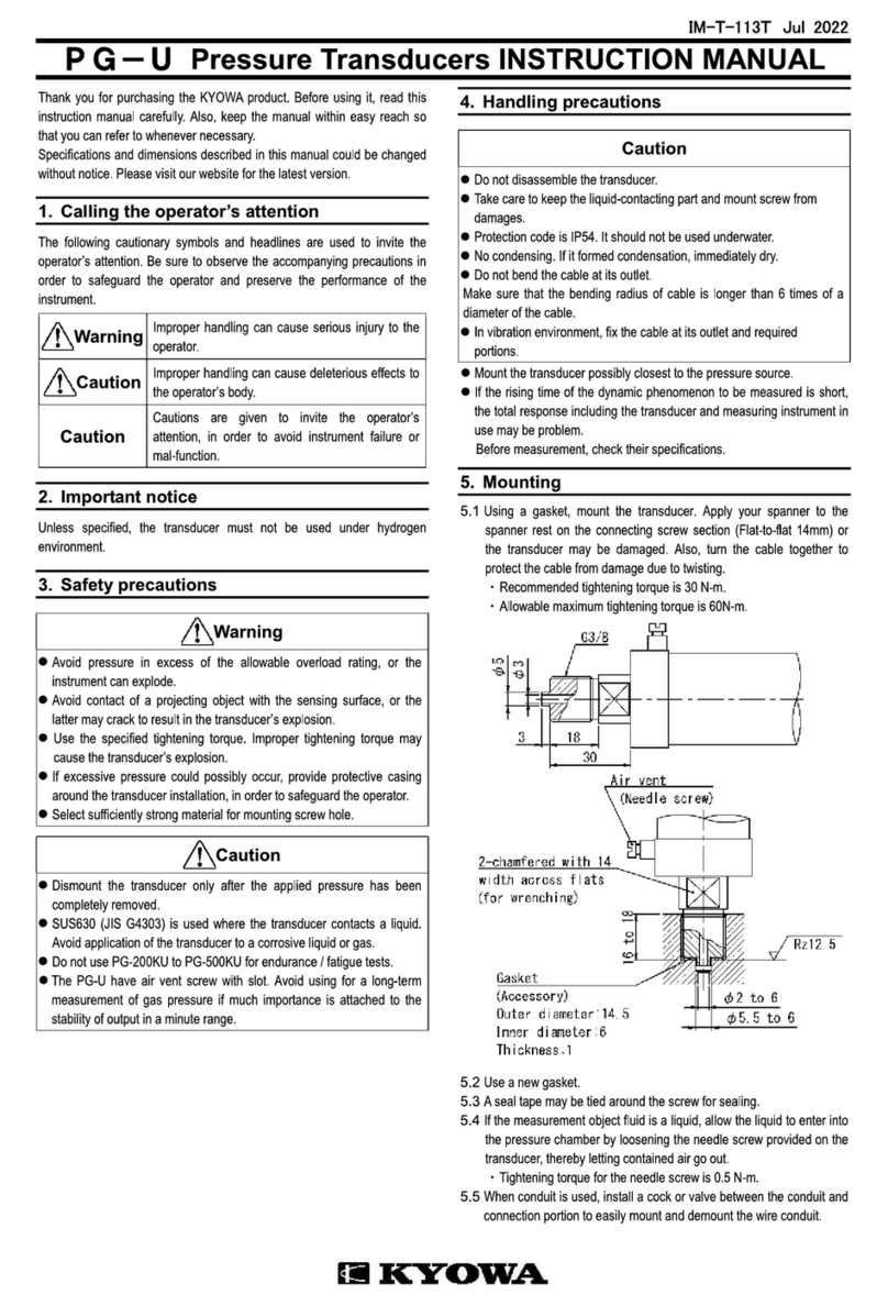
MBS EMBSIN 101 I User manual

1
BA 101 I 128 042 09/08
Betriebsanleitung
Messumformer für Wechselstrom EMBSIN 101 I
Mode d’emploi
Convertisseur de mesure pour courant alternatif EMBSIN 101 I
Operating Instructions
Transducer for AC current EMBSIN 101 I

6
Operating Instructions
Transducer for AC current EMBSIN 101 I
Safety precautions to be strictly observed are marked with
following symbols in the Operating Instructions
The instruments must only be dispo-
sed of in the correct way!
Contents
1. Read first and then … ................................................6
2. Brief description..........................................................6
3. Technical data .............................................................6
4. Mounting .....................................................................6
5. Electrical connections.................................................6
6. Commissioning and maintenance...............................8
7. Releasing the transducer ............................................8
8. Instrument admission.................................................. 8
9. Dimensional drawing................................................... 8
1. Read first and then …
The proper and safe operation of the device
assumes that the Operating Instructions is
read carefully and the safety warnings given
in the various Sections
4. Mounting
5. Electrical connections
are observed.
The device should onlybehandled byappropriately trained
personnel who are familiar with it and authorised to work
in electrical installations.
Unauthorized repair or alteration of the unit invalidates
the warranty.
2. Brief description
The transducer EMBSIN 101 I is designed to convert a sinus-
oidal AC current into a DC current or voltage proportional to
the measured value.
3. Technical data
Measuring input
Nominal frequency: 50/60 Hz
Nominal input current: Acc. to type 0 - 1 or 0 - 5 A
non-standard ranges
0 - 0.8 to 0 - 1.2 A
or 0 - 4 to 0 - 6 A
Own consumption: ≤ 5 mV · INwith input end value
Measuring output
DC current: 0 - 1 to 0 - 20 mA resp. live-zero
0.2 - 1 to 4 - 20 mA
Burden voltage: 15 V
External resistance: See Section “5. Electrical connec-
tions”
With 2-wire
connection: Power supply via output leads,
4 - 20 mA,
External resistance see Section
“5. Electrical connections”
Load-independent
DC voltage: 0 - 1 to 0 - 10 V resp. live-zero
0.2 - 1 to 2 - 10 V
External resistance: See Section “5. Electrical connec-
tions”
Response time: < 300 ms
Power supply
AC voltage: 24, 110, 115, 120, 230 or 400 V
± 15%, 50 / 60 Hz
Power consumption approx. 3 VA,
see Fig. 2
Options
DC voltage: 24 V, – 15 / + 33 %,
power consumption approx. 1.5 W,
see Fig. 3
With 2-wire connection and output
4…20 mA (power supply via output
leads) 24 V, – 50/+ 33%,
power consumption 1.5 W,
see Fig. 4
DC or AC voltage: DC, AC power pack
(DC or 40 - 400 Hz)
85 - 230 V DC/AC or
24 - 60 V DC/AC
DC – 15/+ 33%, AC ± 15%
Power consumption
≤ 1.5 W resp. ≤ 3 VA, see Fig. 5
Accuracy (acc. to IEC 688)
Reference value: Output end value
Accuracy: Class 0.5
Safety
Pollution degree: 2
Installation category: III
Reference conditions
Operating temperature: – 10 to + 55 °C
Storage temperature: – 40 to + 70 °C
Relative humidity of
annual mean: ≤ 75 %
Altitude: 2000 m max.
Indoor use statement

7
4. Mounting
The EMBSIN 101 I can be mounted on a top-hat rail.
Note “Environmental conditions” in Section
“3. Technical data” when determining the place of
installation!
Simply clip the device onto the top-hat rail (EN 50 022) (see
Fig. 1).
Fig. 1. Mounting onto a top-hat rail 35 ×15 or 35 ×7.5 mm.
5. Electrical connections
Connect the leads acc. to the instructions on nameplate.
Make sure that all cables are not live when
making the connections!
Impending danger by high power supply
voltage!
Take care of current transformers!
Also note that, …
…thedatarequiredtocarry out the prescribedmea-
surementmustcorrespond tothosemarkedon the
nameplate of the EMBSIN 101 I ( measuring
input, measuring output and power
supply, see Fig. 6)!
…the resistance in the output circuit
– may not overrange the value
Rext max. [kΩ] ≤ 15 V
IAN [mA]
(IAN = current output end value)
– with power supply via output leads (2-wire
connection, output 4 - 20 mA) dependent on
power supply H (12 - 32 V DC)
1000
0122432
0
600
External
resistance [Ω]
H = Power supply [V]
Rext max. [kΩ] = H [V] – 12 V
20 mA
– may not underrange the value
Rext min. [kΩ] ≥ UAN [V]
10 mA
(UAN = voltage output end value)
…the measurement outputcables should be twisted
pairs and run as far as possible away from heavy
current cables!
In all other respects, observe all local regulations when
selecting the type of electrical cable and installing them! Fig. 6. Declaration to type label.
Measuring output
Output signal
Manufacturer
Works No.
Measuring input
Measuring range
Measured quantity
Conformity
marks
Power supply
1234
5678
3,7
EMBSIN 101I
Mat: 128349 / 4161903
0...5A 50/60 Hz
4 –20 mA
230 VAC
1234
5678
–+
I
Fig. 2. AC power supply
1234
5678
–+
I
–+
Fig. 3. DC power supply.
1234
5678
I
–+
Rext +
-
Fig. 4. Power supply via
output leads.
1234
5678
–+
I
–
Fig. 5. DC, AC power supply,
in version with built-in
DC, AC power pack.
I = Current measuring input = Measuring output
= Power supply

8
6. Inbetriebnahme und Wartung
6. Mise en service et entretien
6. Commissioning and maintenance
Hilfsenergie und Messeingang einschalten.
Der Messumformer ist wartungsfrei.
Enclencher l’alimentation auxiliaire et l’entrée de mesure.
Le convertisseur de mesure ne nécessite pas d’entretien.
Switch on the power supply and the measuring input.
No maintenance is required.
7. Demontage-Hinweis
7. Indication pour le demontage
7. Releasing the transducer
Messumformer gemäss Bild 7 von Tragschiene abneh-
men.
Démonter le convertisseur du rail support selon Fig. 7.
Release the transducer from a top-hat rail as shown in
Fig. 7.
Bild 7
Fig. 7
8. Gerätezulassung
8. Admission d’appareil
8. Instrument admission
Germanischer Lloyd
Lloyd germanique
9. Mass-Skizze
9. Croquis d’encombrement
9. Dimensional drawing
114
112
70
35
Bild 8. Gehäuse MBS/SP1 auf Hutschiene (35 ×15 mm oder
35 ×7,5 mm) nach EN 50 022.
Fig. 8. Boîtier type MBS/SP1 sur rail «à chapeau» (35 ×15 mm ou
35 ×7,5 mm) selon EN 50 022.
Fig. 8. Housing type MBS/SP1 onto a top hat rail (35 ×15 mm or
35×7.5 mm) acc. to EN 50 022.
Other MBS Transducer manuals
Popular Transducer manuals by other brands
Simrad
Simrad ES38DD - REV E installation manual

Clark Synthesis
Clark Synthesis TST209 installation guide

Nexus
Nexus NX2 installation manual
Balluff
Balluff BTL5-S1 Series Condensed guide
NK TECHNOLOGIES
NK TECHNOLOGIES DT Series instructions
Airmar Technology Corporation
Airmar Technology Corporation R99 owner's guide
