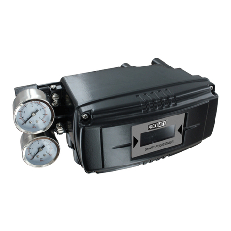
Dwyer Instruments W.E. Anderson 150N Series User manual

Series 150N Pneumatic Positioner
Installation and Operating Instructions
Bulletin F-56
W.E. ANDERSON DIV., DWYER INSTRUMENTS, INC.
P.O. BOX 358 • MICHIGAN CITY, INDIANA 46361 U.S.A.
Phone: 219/879-8000 www.dwyer-inst.com
Fax: 219/872-9057 e-mail: info@dwyer-inst.com
Bulletin F-56 6/27/05 9:37 AM Page 1

TABLE OF CONTENTS
SECTION TITLE PAGE
1.0 INTRODUCTION..................................................................................................3
1.1 MODEL DESIGNATION...........................................................................................3
1.2 SPECIFICATIONS...................................................................................................4
2.0 INSTALLATION.....................................................................................................5
2.1 SHIPPING AND STORAGE.....................................................................................5
2.2 MECHANICAL INSTALLATION................................................................................5
2.2.1 PROCEDURE..............................................................................................6
2.3 PNEUMATIC CONNECTIONS.................................................................................9
2.3.1 PIPING......................................................................................................10
2.3.2 INSTRUMENT AIR REQUIREMENTS.........................................................10
2.4 CAM INSTALLATION............................................................................................11
2.4.1 CAM IDENTIFICATION...............................................................................11
2.4.2 EQUIPMENT NEEDED...............................................................................11
2.4.3 PROCEDURE............................................................................................11
3.0 CALIBRATION....................................................................................................16
3.1 EQUIPMENT NEEDED..........................................................................................16
3.2 PROCEDURE.......................................................................................................16
4.0 PRINCIPLE OF OPERATION.............................................................................20
5.0 MAINTENANCE..................................................................................................22
5.1 RESTRICTION......................................................................................................22
5.2 FILTER SCREENS................................................................................................22
LIST OF ILLUSTRATIONS
SECTION TITLE PAGE
2-1 Cam and Associated Hardware..............................................................................7
2-2 Typical Positioner Mounting and Feedback Pin Connection....................................8
2-3 Standard Cam Characteristics..............................................................................13
2-4 Cam Installation, A Side Example.........................................................................14
2-5 Cam Installation, B Side Example.........................................................................15
3-1 Calibration............................................................................................................17
4-1 Schematic............................................................................................................21
9/94
PAGE 2 BULLETIN F-56
Bulletin F-56 6/27/05 9:37 AM Page 2

1.0 INTRODUCTION
The Model 150P Valve Positioner is a cam characterized, double-acting, pneumatic valve positioner
that accepts a 3-15 or 3-27 psig input signal and converts it to a pneumatic output to position a con-
trol valve actuator. The Positioner can be used with either rectilinear or rotary, single or double acting
actuators. A selection of cam profiles is available.
A high-gain, piloted spool valve is used to load the actuator for positioning in response to an input sig-
nal. Mechanical feedback is provided by a characterized cam.
No additional parts are necessary to change between single or double acting actuators or
direct/reverse action.
1.1 MODEL DESIGNATION
Each Positioner has a nameplate identifying the model number. The following decodes the model num-
ber on the nameplate. Before installing or servicing a Positioner, review the nameplate information.
TYPE
150N Pneumatic Valve Positioner
ACTION
L Rectilinear
R Rotary
CAM PROFILE
1 Standard Linear
2 Standard Rotary
INPUT
1 3 to 15 PSIG
2 3 to 27 PSIG
150N L 1 1 SAMPLE MODEL NUMBER
9/94
BULLETIN F-56 PAGE 3
Bulletin F-56 6/27/05 9:37 AM Page 3

PAGE 4 BULLETIN F-56
1.2 SPECIFICATIONS
Connections: 1/8˝ NPT
Input: 3-15 PSIG (.21-1.1 KG/CM2), 3-27 PSIG (.21-1.9 KG/CM2)
Supply: 30 PSIG (2.1 KG/CM2) minimum, 150 PSIG (10.5 KG/CM2) maximum
Supply Pressure Change Effect: output pressure changes less than 0.3% of span for a 5 PSIG (.35 KG/CM2)
change
Air Consumption: 0.7 SCFM (.33 L/S) at 60 PSIG (4.22 KG/CM2) supply
Air Pilot Capacity: 7.5 SCFM (3.5 L/S) at 60 PSIG (4.22 KG/CM2) supply
Adjustable Range: ±30% of input span or maximum rated travel
Stroke: Rectilinear, 1/2˝ to 2˝
Temperature Limits: -40°F to 180°F (-40°C to 82°C)
Weight: 2.5 lbs. (1.3 kgs)
Gauges............ Two: 0-160 PSIG (0-11.2 KG/CM2) gauges to monitor output
pressure;
One: 0-30 PSIG (0-2.1 KG/CM2) gauge to monitor input
pressure.
Position Indictor Indicator and tape scale to indicate valve position (rotary actuators only).
PERFORMANCE
Repeatability: 0.1% of span
Linearity: ±1% of span
Hysteresis: less than 0.75% of span
Dead Band: less than 0.1% of span
Response Level: less than 0.1% of span
9/94
Bulletin F-56 6/27/05 9:37 AM Page 4

BULLETIN F-56 PAGE 3
2.0 INSTALLATION
This section provides information pertaining to installation of a Series 150N Valve Positioner.
This entire section should be reviewed before proceeding with the installation.
Positioner installation is dependent upon the type of valve actuator and its characteristics, and the
effect of the valve on the process. Obtain this information before proceeding with the installation.
Operating temperature limits are stated in the Specifications section of this Instruction. The tempera-
ture in the selected location must not exceed the specified operating temperatures.
CAUTION
Exceeding the specified operating temperature limits can
adversely affect performance and may cause damage to the
Positioner.
The Positioner will need to be calibrated before being put into service.
2.1 SHIPPING AND STORAGE
If the Positioner is to be stocked, stored, or shipped to another location prior to piping, make sure that
the factory installed plastic plugs are in the pneumatic ports to prevent entry of moisture, dirt, or other
contaminant.
2.2 MECHANICAL INSTALLATION
Refer to Page 1 for dimensions and mounting hole locations.
Rigidly mount Positioner to actuator to prevent relative motion. The Positioner may be mounted in any
orientation. Feedback torque is 7 inch/lbs. maximum. The location must provide access for:
• Mechanical interconnecting of Positioner and actuator
• Routing of pneumatic piping
• Removing of access cover
• Servicing
Note that the extension spring and related parts mentioned in the following procedures, and shown in
Figure 2-1, are present only when a quick opening cam is used.
Bulletin F-56 6/27/05 9:37 AM Page 5

PAGE 6 BULLETIN F-56
2.2.1 Procedure
1. Loosen cover screws and rotate cover (and gasket) to provide access. See Page 1.
2. If present, remove extension spring from spring anchor (spring may be disconnected in a new
Positioner shipped from the factory). Then remove screw, washer, and anchor. See Figure 2-1.
3. Slightly loosen hex nut or standoff so input shaft is free to turn without turning cam (7/16˝ socket
needed).
4. If removed in step 2, loosely reinstall the spring anchor, washer, screw, and extension spring removed
in step 2.
5. For feedback connection between Positioner and actuator, refer to either A or B depending upon
type of actuator to be used.
A. RECTILINEAR ACTUATOR
Figure 2-2 shows Positioner and sample actuator. Fabricate and install a slotted bracket and feed
back pin based on following statements:
• Feedback level must be perpendicular to actuator stem with actuator at mid-stroke.
• Connection between actuator stem and feedback lever is typically made using a slotted brack
et attached to actuator stem and a feedback pin attached to the feedback lever. The slotted
bracket must be rigid and motion must be transferred without deflection.
• Figure 2-2, details A and B, show the feedback pin fixed to feedback lever, the preferred
method. The distance from the centerline of feedback pin to centerline of input shaft must equal
actuator stroke.
• Figure 2-2, detail C shows feedback pin fixed to slotted bracket, an alternate method that caus
es an increase in linearity error of approximately 2%. The distance from the centerline of free
end of feedback pin to centerline of Positioner input shaft must equal actuator stroke x 0.866.
B. ROTARY ACTUATOR
Fabricate and install a coupling based on the following statements:
• Couple the 0.5˝ square Positioner input shaft to actuator shaft.
• Shaft centerlines must be in-line to minimize friction and binding as shafts rotate.
6. Mount Positioner on actuator.
Bulletin F-56 6/27/05 9:37 AM Page 6

BULLETIN F-56 PAGE 7
FIGURE 2-1 Cam and Associated Hardware
Bulletin F-56 6/27/05 9:37 AM Page 7

PAGE 8 BULLETIN F-56
FIGURE 2-2 Typical Positioner Mounting and Feedback Pin Connection
Bulletin F-56 6/27/05 9:37 AM Page 8

BULLETIN F-56 PAGE 9
2.3 PNEUMATIC CONNECTIONS
Pneumatic connections are shown on page 1 and listed below:
IN - Input (or instrument) connection
V1- No. 1 valve connection
V2 - No. 2 valve connection
S - Supply connection
Valve connections are used either independently or together to load the valve actuator. A user supplied
1/8˝ NPT pipe fitting is 12 foot-pounds. When only one valve connection is used, a user supplied 1/8˝
NPT pipe plug is required for the unused connection.
CAUTION
Pressure in excess of 150 psig to any connection may cause
damage to the Positioner.
Supply pressure to Positioner must not exceed actuator
maximum pressure rating.
Refer to the table to determine the required pneumatic connections between the Positioner and the
actuator.
ACTUATOR POSITIONER ACTION CONNECTIONS
TYPE
Single acting Direct acting (output increases Connect V2 and plug V1
with increasing input signal)
Single acting Reverse acting (output decreases Connect V1 and plug V2
with increasing input signal)
Double acting --- 1. Note actuator position desired for
minimum input signal to Positioner.
2. Connect V2 to actuator port that
causes actuator to move away from
position noted in above step.
3. Connect V1 to remaining port.
Bulletin F-56 6/27/05 9:37 AM Page 9

PAGE 10 BULLETIN F-56
2.3.1 Piping
All connections are 1/8˝ NPT.
User supplied materials:
• Scale free piping at least 3/16˝ OD
• 1/8˝ NPT pipe fitting is needed for each connection used; the maximum torque to be applied
when tightening a fitting is 12 foot-pounds
• 1/8˝ pipe plug to plug an unused port
Piping recommendations:
• Blow out all piping before connections are made to prevent dirt, chips, or debris from entering
the Positioner.
• Use pipe sealant sparingly and only on male threads. A non-hardening sealant is strongly
recommended.
• Connect the Positioner to a source of clean, oil-free instrument air. Instrument air requirements
are given in the following section. Failure to do so will increase the possibility of a malfunction
or deviation from specified performance.
2.3.2 Instrument Air Requirements
Instrument quality air must be supplied to the Positioner.
CAUTION
Synthetic compressor lubricants in the air stream at the Positioner
may cause it to fail.
There are many types of synthetic lubricants. Some may not be compatible with the materials used in
the construction of the Positioner. Wetting of these materials by such an oil mist of vapor may cause
them to deteriorate. This can result in failure of the Positioner. A list of materials used in the Positioner
is found in the SPECIFICATIONS section.
Requirements for a quality instrument air supply can be found in the Instrument Society of America’s
“Quality Standard for Instrument Air” (ISA-S7.3). Basically this standard calls for the following:
Particle Size - The maximum particle size in the air stream at the instrument should be no larger than 3
microns.
Bulletin F-56 6/27/05 9:37 AM Page 10

BULLETIN F-56 PAGE 11
Dew Point - the dew point, at line pressure, should be least 10°C (18°F) below the minimum tempera-
ture to which any part of the instrument air system is exposed at any season of the year. Under no cir-
cumstances should the dew point, at line pressure, exceed 2°C (35.6°F).
Oil Content - The maximum total oil or hydrocarbon content, exclusive of non-condensibles, should not
exceed 1 ppm under normal operating conditions.
2.4 CAM INSTALLATION
This section provides a cam installation procedure which applies to all Model 150N Positioners. It
assumes that the Positioner is mounted and Pneumatic connections are made. Use this procedure
when changing the cam or cam side.
2.4.1 Cam Identification
A number-letter combination (e.g., 1A and 1B) is used on each side of a cam for identification. The
number designates the type of cam (i.e., linear, modified equal percentage, or quick opening) as indi-
cated in the model designation. The letter denotes the side of the cam to be used for Positioner oper-
ation.
Each side of a cam also has three marked and graduated input ranges (i.e., 0-100% for whole range
and 0-50% and 50-100% for split ranges).
Figure 2-3 shows the standard cam characteristics defined in the model designation.
2.4.2 Equipment Needed
• 7/16˝ open-end wrench
• Torque wrench, set to 75 inch-pounds
• 7/16˝ deep socket
• Medium slotted screwdriver
2.4.3 Procedure
1. Ensure air supply and input signal to Positioner are turned off.
2. Determine desired direction of rotation of the cam for an increasing input signal.
1) Select side of cam needed. Use A side of cam for clockwise rotation or use B side for coun
terclockwise rotation.
2) Select cam lobe corresponding to the desired whole or split range.
Bulletin F-56 6/27/05 9:37 AM Page 11

PAGE 12 BULLETIN F-56
3. For access to cam and loosening of cam mechanism, perform the following steps.
1) Rotate access cover (and gasket). Refer to Page 1.
2) If present, remove extension spring from spring anchor; then remove screw, washer, and
anchor. See Figure 2-1.
3) Slightly loosen hex nut or standoff so input shaft is free to turn without turning cam (7/16˝
socket needed).
4. If it is necessary to use other side of cam: remove nut or standoff, turn cam over, and install the
washer and standoff; do not tighten Standoff. Cam must be free to rotate.
5. Index cam as follows:
For the following steps, refer to Figure 2-4 when using the A side of a cam or to Figure 2-5 when
using the B side of a cam. Detail A shows cam nomenclature.
1) Turn on the supply pressure.
2) Ensure that valve actuator is seated in the position desired with no Positioner input signal. If
it is not, loosen fine zero locknut and adjust the fine zero thumbwheel as needed; tighten fine
zero locknut.
3) Carefully align minimum input index line with center of cam follower bearing pin and tighten
cam locknut or standoff to 70-75 in./lbs torque.
4) If removed in step 3 on the preceding page, reinstall, spring anchor and extension spring.
5) Loosely reinstall the access cover (and gasket) to prevent both inadvertent damage to
Positioner components and introduction of dirt and other foreign matter into the Positioner.
6) Turn off supply pressure.
6. Proceed to section 3 Calibration.
Bulletin F-56 6/27/05 9:37 AM Page 12

BULLETIN F-56 PAGE 13
FIGURE 2-3 Standard Cam Characteristics
Bulletin F-56 6/27/05 9:37 AM Page 13

PAGE 14 BULLETIN F-56
FIGURE 2-4 Cam Installation, A Side Example
Bulletin F-56 6/27/05 9:37 AM Page 14

BULLETIN F-56 PAGE 15
FIGURE 2-5 Cam Installation, B Side Example
Bulletin F-56 6/27/05 9:37 AM Page 15

3.0 CALIBRATION
Calibrate a Positioner before placing it in service and after repair. Figure 3-1 locates the calibration
adjustments.
This section accommodates two styles of calibration adjustments: concentric and separate. The con-
centric style is the most common and appears on current Positioners.
To determine the style of calibration adjustment in the Positioner to be calibrated, read the following
statements while referring to Figure 3-1.
• Concentric - Span Locknut and Coarse Zero Lockscrew are concentric - a straight-slot screw
within a hexagonal nut.
• Separate - Separate Range Spring (Span) and Coarse Zero Lockscrews are provided. Both
lockscrews may be hard to see since they are located on almost opposite sides of the Range
Spring assembly.
Select the appropriate calibration procedure for the Positioner at hand.
3.1 EQUIPMENT NEEDED
Pressure regulator, adjustable from 0 to 30 psig, qty. 1
Pressure gauge, 0 to 30 psig, qty. 1
Small slotted screwdriver, qty. 1
3/8˝ open-end wrench, qty. 1
1/4˝ nutdriver (CONCENTRIC), qty. 1
3.2 PROCEDURE
1. Refer to Figure 2-1 and open housing cover. Loosen two holding screws (one is identified as the
cleaning wire) and pivot cover (and gasket) clockwise to gain access inside housing. Turn upper right
holding screw finger-tight to hold cover in position.
2. Calibration Preset
If Positioner has been either serviced and parts have been replaced or the calibration otherwise dis
turbed, the Fine Zero Thumbwheel and Range Spring can be preset to speed calibration. Otherwise
proceed to step 3.
1) Adjust thread projection above Fine Zero Thumbwheel by loosening Fine Zero Locknut and turning
Fine Zero Thumbwheel. One thread (1/16˝) should project above the Fine Zero Thumbwheel.
PAGE 16 BULLETIN F-56
Bulletin F-56 6/27/05 9:37 AM Page 16

BULLETIN F-56 PAGE 17
FIGURE 3-1 Calibration
Bulletin F-56 6/27/05 9:37 AM Page 17

PAGE 18 BULLETIN F-56
2) CONCENTRIC - Adjust Range Spring active coils by loosening Range Spring Locknut and turning
Range Spring. Four to four and one-half active coils are desired for a standard input span.
SEPARATE - Adjust Range Spring active coils by loosening Range Spring Lockscrew and turning
Range Spring. Four to four and one-half active coils are desired for a standard input span.
3) CONCENTRIC - Tighten Fine Zero Locknut and Range Spring Locknut after making adjustment.
SEPARATE - Tighten Fine Zero Locknut and Range Spring Locknut after making adjustment.
3. Turn on supply pressure.
4. Zero Adjustment
A. Fine Zero Adjustment
1) Set input signal to desired minimum range value.
2) Loosen Fine Zero Locknut.
3) Turn Fine Zero Thumbwheel until desired valve position is reached and tighten Fine Zero
Locknut.
If Positioner can not be zeroed, proceed to Coarse Zero Adjustment. Otherwise proceed to
step 5 Span Adjustment.
B. Coarse Zero Adjustment
1) Center fine zero adjustment by loosening Fine Zero Locknut and turning Fine Zero Thumbwheel
so that approximately one thread (1/16˝) of the Fine Zero Screw projects above Fine Zero
Thumbwheel.
2) Loosen Coarse Zero Lockscrew 1/4 turn. The Span Nut must be tight against the spring.
3) CONCENTRIC - Turn Coarse Zero and Span Nut and Fine Zero Thumbwheel simultaneously in
the same direction until valve is in desired position. Continue to turn Coarse Zero and Span
Nut until Coarse Zero Lockscrew and Range Spring Locknut are accessible.
Bulletin F-56 6/27/05 9:37 AM Page 18

BULLETIN F-56 PAGE 19
SEPARATE - Turn Coarse Zero and Span Nut and Fine Zero Thumbwheel simultaneously in the
same direction until valve is in desired position. Continue to turn Coarse Zero and Span Nut until
Coarse Zero Lockscrew and Range Spring Locknut are accessible.
4) CONCENTRIC - Tighten Coarse Zero Lockscrew, then tighten Range Spring Locknut.
SEPARATE - Tighten Coarse Zero Lockscrew.
5) Repeat fine zero adjustment in A above.
5. Span Adjustment
1) Increase input to produce desired valve full-scale motion and note input span.
- If span is correct, calibration is complete.
- If span is incorrect, proceed to step 2.
2) Reduce input to zero value.
3) CONCENTRIC - Loosen Range Spring Locknut and Fine Zero Locknut and adjust the number of
active range spring coils as follows.
SEPARATE - Loosen Range Spring Locknut and Fine Zero Locknut and adjust the number of
active range spring coils as follows.
- If input span is narrow, reduce number of active coils.
- If span is wide, increase number of active coils.
NOTE
For a 12 psi input span, turning the range spring 15° or 1/16˝ adjusts span
about 1%.
4) CONCENTRIC - Tighten Range Spring Locknut and Fine Zero Locknut.
SEPARATE - Tighten Range Spring Locknut and Fine Zero Locknut.
5) Repeat zero and span adjustments until Positioner is calibrated.
NOTE
If a major change in span adjustment (10% or more) has been made,
re-adjust coarse zero.
This completes the procedure.
Bulletin F-56 6/27/05 9:37 AM Page 19

PAGE 20 BULLETIN F-56
4.0 PRINCIPLE OF OPERATION
The following describes a direct-acting Positioner operating a valve with a double-acting actuator in
response to an increased input signal. Refer to Figure 4-1.
The input signal, representing the desired valve position, is applied between the two diaphragms of the
input diaphragm assembly. Since the bottom diaphragm has a larger effective area than the top
diaphragm, an increase in the input signal will move the diaphragm assembly downward.
The assembly operates the nozzle flapper over the nozzle to control the pilot air pressure acting on the
top of the pilot diaphragm assembly. Pilot air to the nozzle and to the top of the diaphragm assembly
is taken from the air supply via the restriction.
The restriction and nozzle form a pressure divide circuit. An increase in the input signal causes the
input diaphragm assembly to move the nozzle flapper upward and away from the nozzle. This increas-
es pilot air flow through the nozzle to the pilot exhaust and decreases the pilot air pressure acting on
the top of the pilot diaphragm assembly.
The pilot diaphragm assembly and the end cap diaphragm operate the spool to control the V1 and V2
outputs to the valve actuator. The spool operates over the V1 and V2 ports and simultaneously sup-
plies one output and exhausts the other on an input signal change, or it blocks both ports so they nei-
ther supply nor exhaust when the positioner is in balance.
The spool is moved upward by air supply pressure acting on the bottom of the end cap diaphragm in
response to a decrease in pilot air pressure on top of the pilot diaphragm assembly. This connects air
supply from the supply port to the V2 port and increases the output of the V2 connection. At the same
time, the V1 port is connected to the V1 exhaust to decrease the output of the V1 connection.
The resultant change in valve position is fed back to the positioner via the cam. The increase in the V2
output causes the cam to rotate clockwise moving the span lever upward and increasing range spring
tension. The upward force of the range spring causes the input diaphragm assembly to move the noz-
zle flapper downward and closer to the nozzle. This increases the pilot pressure on top of the pilot
diaphragm assembly and forces the spool to move downward.
When the valve reaches the position called for by the input signal, the upward force of the range spring
will equal the downward force of the input signal. At this time, the positioner will be in balance will the
spool blocking both V1 and V2 ports so that neither is supplying nor exhausting to the valve actuator.
Bulletin F-56 6/27/05 9:37 AM Page 20
Table of contents
Other Dwyer Instruments Valve Positioner manuals